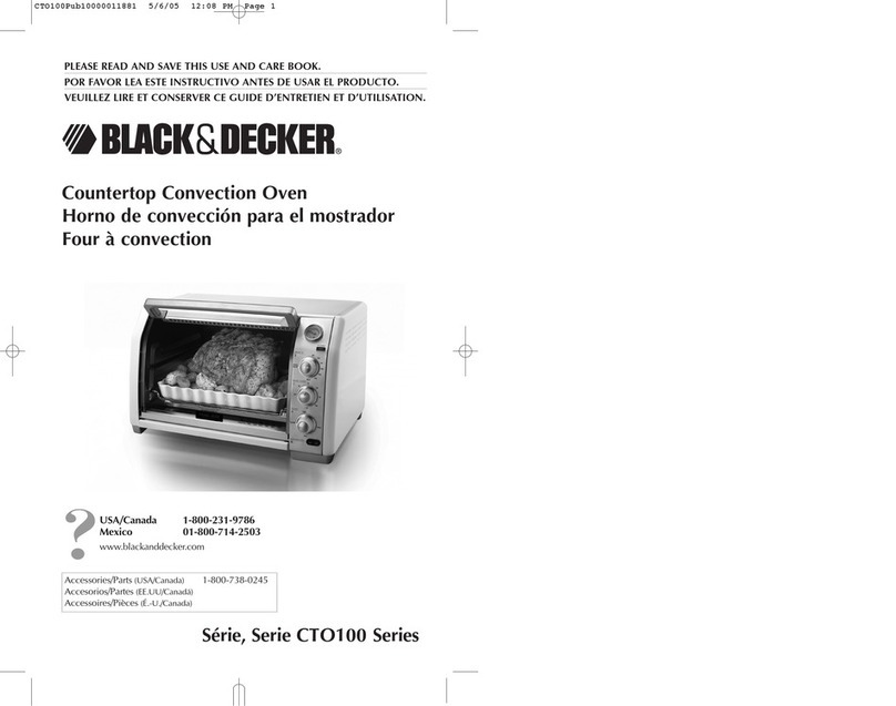
Lindberg/Blue M01490PA User manual

Mechanical
Convection Ovens
Models: M01490PA/M01490SPA
M01490PC/M01490SPC
M0149OPU/M01490SPU
Installationand Operation Manual
Table
of
Contents
Introduction
.
.
.
.
...
.
..
.
.
.
..
.
..
.
..
.
.
.
..
..
.
.
1
Safety Considerations
..
.
.
..
..
.
......
.
...
.
.
.2
Pre-Installation
..
.
.......
.
.....
.
..
.
.
...
.
...
2
Installation
.
.
.
..
..
.
..
.
..
....
.
.
.
.
....
..
.
.
.
.3
Start Up
.
.
.
.
.
..
.
.
.
.
..
. .
..
.
.
.
..
.
....
.
..
.
.
.4
Operation
-
UP1
50
Controller
.
..
.
.....
.
.
.
.
.
.
.5
Maintenance
.
.
..
.
..
..
.
.
.
.
.
..
.
..
.
..
.
..
..
.
.7
Troubleshooting
.
.
..
.
..
.
.
.
.
.
.
.
.....
...
..
.
.
.8
Wiring Diagramsand Replacement Parts.
..
.
...
.9
Warranty
..
.
..
..
.
..
.
.
...
.
.
.
..
.
.
.
..
.
....
.
.
11
O
2000
LindberglBlue
M
All
rightsreserved
Printed In
U.S.A.

Mechanical ConvectionOvens Table of Contents
Table of Contents
.......................................................................
1 Introduction
1
1.
1 FeaturesandBenefits
....................................................................
I
1.2 FrontPanelComponents
..................................................................
I
1.3 ComponentsLocatedOff the Panel
..........................................................
1
...........................................................................
1.4 Specifications
I
2
Safety Considerations
..............................................................
2
3
Pre4nstallation
....................................................................
2
3.1
Unpacking
..............................................................................
2
3.2 Atmospheresystems
.....................................................................
2
........................................................................
4
Installation
3
4.1 Location
...............................................................................
3
.................................................................................
4.2 Wiring
3
4.3 ExhaustModifications
.....................................................................
3
5 Startup
..........................................................................
4
.........................................................................
5.1 Ovenoperation 4
..................................................................
5.2
IntakeandExhaustVents 4
........................................................
6
Operation
-
UP150Controller 5
6.1 NormalControllerOperation
................................................................
5
6.2 Basicoperation
.........................................................................
6
6.3 EnteringProgramParameters
..............................................................
6
6.4 Runningtheprogram
.....................................................................
6
6.5 UsingtheHoldFunction
...................................................................
6
7
Maintenance
......................................................................
7
7.1 Cleaning
...............................................................................
7
7.2 HeatingElements
........................................................................
7
7.3 BlowerMotor
...........................................................................
7
7.4 OvenOvertemperatureSystem
.............................................................
7
7.5 Doorsystemcheck
......................................................................
7

MechanicalConvectionOvens Table of Contents
8
Troubleshooting
...................................................................
8
..............................................
9
Wiring Diagrams and Replacement Parts
9
10
Warranty
.........................................................................
I1
10.1 DomesticWarranty (UnitedStates and Canada)
...............................................
11
10.2 InternationalWarranty (excludingCanada)
12Months PartsWarranty1
1

Mechanical Convection Ovens Introduction
1
Introduction
TheLindberglBlue M MO SeriesMechanical Convection Ovens
include a microprocessor-based temperature controller which
automatically optimizes control parameters during oven
operation. An internal blower circulates heated air for maximum
temperature uniformity throughout the chamber.
1.1
Featuresand Benefits
Lead-in ports, timers,
10
in.circular chart recorders, anddoor
windows are available.
Programmable controls standard on
"P
models
Intake and exhaust ports included as standard.
Reverse hinged door available.
Stainlesssteel and painted exteriors available.
Type
'7"
thermocouple is standard.
Overtemperature protection is standard.
1.2
Front PanelComponents
The front panel contains the followingfeatures:
Power On switch.
Temperature Controller which senses the process
temperature of the oven and controls the heaters which
supply the heat necessary to achieve the desired setpoint.
The temperature control system includes overtemperature
protection (OTP) which disconnects the heating element
power in overtemperature conditions.
1.3
Components Located Off the Panel
The following components are located off the front panel:
Intake Vent.The intake vent is located at the top of the right
side.
Exhaust Vent. Theexhaust vent is located at the bottom of
the right side.
1.4
Specifications
Table
1.
LindberglBlue M M01490
"P"
Series MechanicalConvection Ovens
Max.
Temp.
"F
("C)
500
(260)
Weight
Ibs.
(kg)
108
(49)
Exterior
Painted
Steel
stainless steel
Voltage
120
V,
50160 Hz.
SinglePhase
240
V,
50160 Hz.
SinglePhase
220
V,
50Hz
120
V,
50160
HZ.
SinglePhase
2~!$l~$~s",''
220
V,
50Hz
SinglePhase
Model
M01490PA
M01490PC
M01490PU
M01490SPA
M01490SPC
M01490SPU
Heater
P;?r
1.6
Line
Current
Amps
13.5
7.0
6.45
13.5
7.0
-
6.45
DimensionsW x D x
H
in. (cm)
Shlpping
(Approximate)
37x31x39
(94
X
79
X
99)
Chamber
19x15~18
(48 x 38x 45) 27x21x29
(60
X
53
X
73)

MechanicalConvectionOvens Safety
ConsiderationslPre-Installation
2
Safety Considerations
WARNING:
Do notmodify or use equipmentin a
mannerotherthanexpressiy intended.Modificationof
equipmentother than that for which itis explicitly
designedcouldcause severe injury or death. Any
customerafter-marketretrofitviolatesthe warranty of
the equipment.
Do not reconfigurethe controller. Any reconfiguration
of the controlinstrumentcouldcause inaccurate
readings,faultyinstrumentvalues, and may causethe
unit to becomeoverheatedand start on fire, causing
personal injury or death, productand property
damage.
Do not modifyor disconnectany safety features
provided. Disconnectionof the unitsafety features
couldallow the unitto becomeoverheated and start
on fire, causing personalinjury or death, product and
propertydamage.
Do notuse components or materialsnot specifically
designedfor this equipment. Failure to complywith
this precautioncould resultindamageto equipment
used or the oven and maycreatean overheat
situation.Also, do not use anythingotherthan OEM
(original equipment manufacturer)exact replacement
equipmentand parts. Not usingOEM replacement
partscouldcause faulty instrumentationreadings,
inoperable equipment, or temperature overshoot.
Bothsituations maycausepersonalinjuryor death,
product,and propertydamage.
Before using, usershall determine the suitabilityand
integrityof the productfor the intendeduse and that
the unit hasnot been altered inany way.
Misapplicationmay compromisethe safety of the end
user or the lifeof the product.
CAUTION:
Do not locatethe oven near
combustible materials,or corrosive or hazardous
fumes or vapors. Incorrectoven locationmay cause
personalinjury, damage to the oven, or property
damage.
CAUTION:
Makesure the ovendoor is closed
when the oven is operating.Operatingthe oven with
thedoor openfor extended periodsof time maycause
personal injury,damage to the oven, or property
damage.
WARNING:
This ovenisnotintendedfor hazardous
A
materials workload processing.Contactyour safety
engineeringstaff beforeprocessingquestionable
loadsin this oven. Contact LindbergIBlueMfor
informationon other productsdesignedto process
hazardous materials.Processingcombustibleor
volatilefluids or materialsin this oven may emit
explosive vapors, which may cause deathor serious
injury.
WARNING:
For proper operationof the unit andfor
A
safety, makesure that the unit is levelwhen installed.
Door mayswing shut on personnel if the unit istilted
and the entire unit may tip when the door isopen.
CAUTION:
Keepcombustiblematerialsawayfrom
A
theheatingelement locatedatthe bottomofthe oven.
Combustible materialsspilledor dropped on the
heatingelementmay cause personalinjury, damage
to theoven, or propertydamage.
3
Pre-Installation
AllstandardLindbergJBlue
M
MechanicalConvectionOvensare
shippedelectrically complete.Positioningand connectingcorrect
electricalserviceare the only requirementsfor placing the oven
into operation.
3.1
Unpacking
Carefullyunpackand inspectthe unit and all accessoriesfor
damage.If you find any damage,keepthepacking materials
and immediately reportthe damageto the carrier. Wewillassist
you withyour claim,ifrequested.
Do not returngoods to
Lindbergmlue
M
without writtenauthorization
When
submitting
a
claim for shippingdamage, request that the carrier
inspect
the shipping containerand equipment.
3.2
Atmosphere Systems
This ovenisnotdesigned to operate incorrosiveenvironments.
WARNING:
Do notlocateunits in areas near
combustiblematerialsor hazardousfumes or vapors.
CAUTION:
Corrosiveenvironments can lead to
shortened lifeor deteriorationof unitand
performance. This unit is not designedto maintaina
positivepressure. Notsuitablefor usewith toxic,
flammable, or volatile materials.

Mechanical Convection Ovens Installation
4
Installation
Do not exceed the electrical and temperature ratings printed on
the dataplate of the oven.
WARNING:
Improper operation of the oven could
resuit in dangerous conditions.TOpreclude hazard
and minimize risk, follow all instructionsand operate
within design limits noted on the datapiate.
4.1
Location
Keep line voltage variations to a minimum for best control
accuracy. Do not locateunit in areas of wide ambient
temperature variation, such as near vents or outdoor entrances.
Placeunit atleast onefoot from walls, although more spacemay
be required for ease of maintenance.
WARNING:
For proper operation of the unit and for
safety, make surethat the unit
is
level when installed.
Door may swing shut on personnel
if
the unit
is
tilted
and the entire unit may tip when the door
is
open.
4.2
Wiring
For detailed wiring information, refer to the wiring diagrams at
the end of this manual.
CAUTION:
Connect the oven to the proper power
source. Failure to use nespecifiedvoltagecan result
in damage to the oven.
All models are supplied with a line cord and electrical plug.
Information for sizing fuse, circuit breaker, or power lines
appears on the oven dataplate and in the general specifications
table (refer to Table
1
on page
1).
Fuse protection must never
exceed
125%
of oven's current rating.
CAUTION:
For personal safety and trouble-free
operation, this unit must be properly grounded before
it
is
used. Always conform to the National Electrical
Code and local codes. Utilize proper grounding
techniques to reduce RFI and EM1 for electronicgear.
Do not connect unit to already overloaded power
lines; lower voltage to unit will decrease power to the
heating elements.
4.3 Exhaust Modifications
Never use an exhaust stack directly between the oven and the
exhaust.
A
draft diverter, vacuum breaker, exhausthood, or
similar device (refer to Figure
1)
must be connected between the
oven and the exhaust. This connection prevents "chimney effect"
which sucks heat out of the chamber and results in slow run-up
time or poor temperature uniformity.
I
Figure
1.
Exhaust Modifications

MechanicalConvection Ovens Start
Up
5
Start
UP
5.1
Oven Operation
1.
Turn on the main power switch. Allow the controller to run
through its initial diagnostics.
2.
Verify operation of the blower motor.
3.
Place workload into oven.
-
To open the oven door, press the button on the black door
latch located on the front of the oven (refer to Figure
2).
-
To close the door, push it shut tightly while pressing the
lower portion of the black doorlatch (refer to Figure
2).
Pressand release
to unlatch
3
Close door and press
here to latch
Figure2. Oven Door Operation
5.2
Intakeand ExhaustVents
The intake vent is located at the top of the right side and the
exhaust vent islocated at the bottom of the right side. For most
applications, vents should be closed during operation of the
oven; closed vents result in more efficient operation and greater
temperature stability. However, there are some applications
which benefit from partially orfully open vents.
Vents should be partially or fully open for the following
application:
To provide operation near ambient temperatures. The oven
may notreliably control temperatures near ambient.Opening
the vents allows sufficient heat loss to permit such operation.
To provide slow cool down of work load. Somework loads
may bedamaged by heat shock when the oven door is
opened. Vents can be opened to allow work load to cool
gradually.
To provide removal of vapors which result from the heating
process. Most drying operations that release vapors are best
performed with vents partially opened to prevent the
accumulation of solid by-products.
WARNING: Workload removed from the chamber
aswell asall chamber surfaces, shelves, door
surfaces (insideand out), door throat area, intake and
exhaust ports, and all items of this nature may be vety
hot. To prevent severe burns, exercise extreme care
at all times to avoid contact with hot surfaces.
Solid materials going into the chamber may become
liquid at high temperature. Handle these liquidswith
care. Do not spill high temperature liquids on the
bottom of the oven. Leakage intothe element
compartment results in equipment damage.
To minimize heat transfer to the operator, turn the unit
off when loading or unloading.
4.
Select the desired alarm setpoint (refer to Section
6
on
page
5).
5.
Press
A
or
7
until thedesired setpointshows on the bottom
line of the display. Refer to Section
6
for instructions on
controller operation.

MechanicalConvection Ovens Operation
-
UP150 Controller
6
Operation
-
UP150
Controller
Table
2.
UP150
ParameterFunctions
Figure
3.
UP150 Control Panel
The oven temperature controller isconfiguredandtuned at the
factory tofunctionwell formostapplications. Occasionally, it
maybeadvisable toconfigurethe temperature controller
differently to suita particularworkingenvironment orprocess.
CAUTION!
Before reconfiguringthe controller, read
hischaptercarefully. Reconfiguringthe controller can
change the unit characteristics anddesign
parameters, which can hamper performance and
makethe equipment dangerous to use.
Formoredetailed instructions, refer to the Yokogawa
UP150
manual.
6.1
Normal ControllerOperation
TheTemperature Controller senses the chamber air temperature
oftheoven (the
PV,
orprocess value) and supplies the heat
necessary toachieve the desired setpoint. Thecontroller includes
an
LED
display anda pushbuttonkeypad. Refer toTable
2
and
Table
3
forlists ofdisplayed parameters and keypadfunctions.
The
UP150
controller willaccept a single programof
up
to
16
segments. This controller includes anautomatic tuning feature
and "Super" control to improvethe performance. Refer tothe
UP150
manual for detailed information.
Table
3.
PushbuttonKeypad
Description
Parameter
'Ode
Faz21y
Value
Button
n
7
Operatingparameters(accessby holding the
SETENT
key)
Function
Pressingandholdingthe SETIENTfor three seconds
advances the displayto the Operation Parameters
Menu.
While intheOperationParameters Menu, use
SETIENTto movefromone parametertothe next, and
to registerchanges you have made insetpoint and
parametervalues.
HoldingSETIENTfor three secondsexits either the
Operationor Setup Parametersmenu.
Usethe UpArrow buttonto increasethetemperature
setpointdisplayandto changeparametervaluesinthe
Operationand Setup Parametermenus. Whenever
you changethe value of a setpointor parameter, the
decimalpointflashesto remindyouto registerthe
changedvaluewith SETIENT.
While inoperating mode, pressingthis key stops
(resets) programoperation.
Use the Down Arrow buttonto decreasethe
temperaturesetpointdisplayandto changeparameter
values inthe Operationand Setup Parameter menus.
Wheneveryou change thevalue of a setpoint or
parameter,the decimalpoint flashes to remindyou to
registerthe changedvalue with SETIENT.
While in operatingmode, pressingthis key starts
(tuns)a program
HoLd
AdV
CtL
At
P
I
d
Ct
FL
bS
LoC
OFF
OFF
Pid
OFF
9.0
202
34
3
OFF
0.0
0
ProgramHold
SegmentAdvance
Controlmode
Auto tuning
Proportionalband (%; PF=10.8)
Integraltime
Derivativetime
Heat cycletime
Sensor filter
PV bias (offset)
Key lock
Setupparameters (accessby setting Lo&-1)
In
SC
5
ON Input type
(J
thenocouple in*C; QF=35)
Superfunction

MechanicalConvection Ovens Operation
-
UP1
50
Controller
6.2
Basic Operation
To operate the UP150 controller, you must first enter a program.
Once the program isentered into the controller, press the "arrow
down" key to run it. Once the program is running, it can be
placed in "hold mode" to maintain the current setpoint. Also, a
"program advance" can be executed to step the program rapidly
through program segments.
6.3 Entering Program Parameters
To access programming mode:
1.Press the SETIENT key for 3 seconds. Make sure the RUN
light isnot lit at this time.
2. "CtL" will bedisplayedin the upper display with "Pid" in the
lower display. Press the SETENTkey repeatedly (7 times)
until LoC is displayed.
3. Press the "arrow down" once to display "-1" in the lower
display.
4. Press the SETIENT key 4 times until Pffi is displayed.
5. Again, press the "arrow down" once to display "-1" in the
lower display.
6.Press the SETIENT key once. Now the programming mode
is accessed.
Prior to entering the actualprogram steps,you will be prompted
for event type settings. This refers to how a relay will function,
either as a "time event" or a "process variable (alarm) event".
To enter a program in program mode:
1.With "EVl" in the upper display and
"0"
in the lowerdisplay,
press the SETIENT key.
2. Next, "AL1" appears in the upper display. A value of
"1"
in
the lower display configuresthe alarm as a high temperature
alarm which is the factory setting. (For more information see
"PV Event (alarm) Function List" in the UP150 Instruction
Manual).
3.The alarm feature may or may not have been utilized,
depending on model. If the alarm feature has been utilized
and the alarm actuates, it will remove electrical power to the
heating elements. If the alarm feature has not been utilized,
setting the alarm will not change unit operation. In either
case, the AL1lightwill illuminate duringan alarm condition.
4. Press the SETlENT key to advance to the Alarm 1 value
(Al). This is the temperature at which the alarm will trip.
This is typically setfor 10"higher than the highest setpoint in
the program.
-
Use the arrow upldown keys to enter the
Alarm 1value. Notice that the decimal point will flash
indicating a change has been made. You must press the
SETENTkey to register a change.
5.Pressthe SETlENT key to advance to the Alarm 1Hysteresis
setting. Enter 1.0.Press the SETIENT key to advance past
the EV2 and AL2settings to the SSP(starting setpoint) value
and enter the setting from the Program Pattern Setting Table.
6.
?
From this point, you will be prompted for SP1 (setpoint
I),
tM1 (time I), SP2
-
tM2, SP3
-
tM3.
..
etc. until all the
program parameters have been entered. Note that Time is
enteredinhours andminutes,forexample, 1.45equals 1hour
and 45 minutes.
7.The controller will accept up to 16setpoints and times. If
fewer than 16are required, enter "OFF" as a time value. This
tells the controller you are finished.
WARNING!
Do not enter
a
setpoint into your
program beyond the maximum operating temperature
of your unit.
8. Next, you will be prompted for a Junction Code (JC). This
determines how the controller will function at the end of the
program. Three Junction Code values are available: "0" will
cause the controller to shut-off its outputs at the end of the
program. This is called the "reset" mode. "1" will place the
controller in "Hold" mode.
"2"
will cause the program to
repeat continuously.
9.
Next you will be prompted for a Wait Zone (WTZ). This is
similar to "guaranteed soak". The factory setting is "OFF"
which means "not used". A wait zone causes the controller
to stop the program clock
if,
at the transition from a ramp
segment to a soak segment, the actual chamber temperature
(PV)
is not close enough to the setpoint. Assume the
controller is programmed to ramp from 25°C to 100°Cin 1
minute. Since theunit does not have the capability to heat-up
this quickly, the controller will change the setpoint from 25"
to 100"in 1minute and wait atbeginning of the 100"
segmentfor the unit to catch upwith the setpointbefore
continuing the program. Theprogram will continue when the
unit temperature (PV) falls within the specified Wait Zone.
The minimum value of the Wait Zone is 1% of the
controller's span for a given input type. In this example, the
span isfrom -200" to 1000°(1200" x 1%
=
12"). This
means, in the above example, the controller will continue the
program when the unit temperaturereaches 88" (100"
-
12"
=
88").
10.The program is now complete and ready to run. Exit the
program parameter setting mode by pressing and holding the
SET/ENT key for 3 seconds.
6.4
Running the Program
To run theprogram, press the Run or "arrow down" key until the
RUN light illuminates.
6.5
Usingthe Hold Function
To hold a running program:
1.Press and hold the SETENTkey for 3 seconds."HoLd" will
appear in the upper display.
2. Press the "arrow up" key so that "on" with flashing decimal
appears in the lower display.
3. Press the SETENTkey to accept.
4. Press and hold the SETlENT key again to return to the
normal display.
To exit the hold mode:
Press and hold the SETIENTkey for3 seconds. "HoLd" will
appear in the upper display. Press the "arrow down" key so that
"OFF" with flashingdecimal appears in the lower display. Press
the SETlENTkey to accept. Press and hold the SETENTkey
again to return to the normal display.

MechanicalConvection Ovens Maintenance
7
Maintenance
WARNING1
When installing, maintaining, or
/1\
removina the fiberalass insulation. the followino
1_1
precautiins will mhimize airborne dust and fib&:
Keep personnel not involved in the installationoutof
thearea.
Use a good vacuum to clean area and equipment.
Use a dust suppressant
if
sweeping
is
necessary.
Do
not
use compressed air.
Use disposable mask suitable for nuisance dust.
Wear long sleeve clothing, gloves, hat, and eye
protectionto minimize skin and eye contact. Do not
wear contact lenses.
Thoroughlywash self after work
is
complete.
Launder work clothingseparate from other clothes
and thoroughlyclean laundering equipment after
use.
If
clothing contains a large amount of dust
andlorfiber, dispose of rather than clean.
Promptly place used fiberglass parts and dust in
plastic bags and dispose of properly.
CAUTION!
Maintenance should only be performed
A
by trained personnel.
WARNING:
Disconnectoven from main power
A
before attempting any maintenance to oven or its
controls.
WARNING:
Before maintaining this equipment,
read the appiicable MsDS (Material Safety Data
Sheets) at the back of this manual.
For wiring schematics and replacement parts specifications, refer
to Section
9
on page
9.
7.1
Cleaning
WARNING:
Disconnectoven from main power
before attempting any maintenance to oven or its
controis.
Cleanthe stainless steel oven interiorwith a cloth dampened with
clean water. Remove stubborn stains with mild dishwashing
detergent.
7.2
Heating Elements
WARNING:
Disconnectoven from main power
before attempting any maintenance to oven or its
controls.
Periodically inspect the heating element and blower wheel
compartments forcleanliness, especially when operating the unit
in adusty environment. Failure to keep these areas clean can lead
to early element burn-out.
To replace heating elements, complete the following steps:
1.
Remove the inner chamber base plate.
2.
Disconnect the leads from element terminals located in the
wiring compartment.
3.
Remove the screwsthat fasten the supportclips.
4.
Remove the support clips from the old elements and attach
them to the new ones.
5.
To install the new elements, reverse the above procedure.
Check gasket seal integrity before securing the inner
chamber base plate.
7.3
Blower Motor
Theblower is fitted with a sealed bearing and requires no
lubrication for the life of the unit.
7.4
Oven OvertemperatureSystem
The Oven Overtemperature System operates only if a problem
occurswith the main controller or solid-state relay. This system
is factory set to prevent catastrophic failure of the oven.
To insure proper operation, test this circuit at least once every six
months.
To test the load overtemperature alarm, complete the following
steps:
1.
Operate the oven without a product load at your normal
operating temperature.
2.
Readjust main temperature control to a temperature above
the load alarm setting (refer to Section
6).
3.
Observe the unit closely until the load alarm trips, indicated
on the controller beside the A1 label.
4.
Reset the main temperature control to normal operating
temperature. Once the unit coolsbelow the alarm setpoint,
the A1indicator will go off.
7.5 Door SystemCheck
WARNING:
Disconnectoven from main power
before attempting any maintenance to oven or its
controls.
Periodically inspect the door latch, trim, catch, and gasket for
signs of deterioration (unusual paint discoloration on the front
face of the oven, softness or deformation of the plastic, slower
response times, cracking or tearing at the gasket). Failure to
maintain the integrity of the door system will reduce the lifespan
of the oven.
To replace the gasket, complete the following steps:
1.
With the oven on its back, remove the inner chamber
mounting screws (under the gasket).
2.
Lift the inner chamber slightly away from the cabinet.
3.
Slipthe gasket off the perimeter of the inner chamber.
4.
Repeat Steps
1
through
3
in reverse orderto install the new
gasket.

Mechanical Convection Ovens Troubleshooting
8
Troubleshooting
WARNING: Troubleshootingprocedures involveworking with highvoltageswhich can cause injury or death.
Troubleshootingshould only be performedby trainedpersonnel.
Table
5
isaguide to troubleshootingcontroller and oven problems.
Table
4.
Oven
Troubleshooting
Problem
Controllerreads P.Er.
Controllerreads b. o
Controllerreadsooo.
Controllerreads
UUU.
Controller reads Err
The controller displaysdo not
illuminate.
Temperaturevaries or fluctuates.
TemperatureOffset.
Oven does not heat.
Slow heatup.
Probable Causes
Abnormal parametervalue
Input burnout
PV exceedseffectiverange
PV is below effective range
Probablehardwarefailure
The
Oven
is
'Onnected
the
power
supply.
Mainswitchis defective.
Fuse(s) blown.
Improperloading.
Poorsensorconnections.
Contaminatedsensor.
Poorventilationof base.
Inletandlor exhaustvents are open.
Inadequatetuning values.
Insufficientstabilizationtime.
Intermittentfailureof switch, controller,
limitswitch, or wiring.
Controllerdegradation andlor sensor
degradation.
No power.
Defectivesolid-staterelay.
Tripped overtemperature control(see
Section
8.5
on page
10).
Defectbesensor.
Controllermalfunction.
Oneor moreheatercoils are burnedout (coil
may be open, shorted, or shorted to ground).
Heater coils are improperlyconnected.
Low linevoltage.
Heavy load in chamber.
Oneheatercoilburnedout.
Open inletandlorexhaust vents.
Improperdoor closure.
Gasket deterioration.
Solution
Checkcontrollerparametersettingsand resetto propervalues.
Checkthe sensorwiring, replacesensor
if
necessary.
Checkthe input typeandrange settingsand correctthem.
Checkthe inputtypeandrange settings andcorrectthem.
CallService for controller repair.
Check oven connection to powersource.
Replacepower switchor controller.
Replace fuse(s) andverify power connections.
Test the unitempty. If resultsare satisfactory, the oven was
improperlyloaded. Redistributethe load.
Check connections. Cleanand tighten.
Replacesensor.
Clearthe area aroundthe base.
Closevents.
Auto-tunethe controller.
Allow loadample timeto reachequilibrium.
Verify wiringconnections.
Offset or bias the controllerandlorreplace the sensor.
Checkpower source, fuses, breakers, andconnections.
Replace solid-staterelay.
Resetthe OTCsystem, following the instructions in Section
8.5.
Replacesensor.
Verify controllerparameterstreplacecontroller.
Replace
Verify powersourcewiththe appropriateschematic
representation.
Installline of sufficientand propervoltage (isolatethe oven from
other electricalloads).
Reduceloadinchamber to allow sufficientcirculation.
Replace heater.
Closevents.
Adjust door latch compression nut to meet gasket on all edges.
Replace gasket.

Mechanical Convection Ovens Wiring Diagramsand Replacement Parts
9
Wiring Diagrams and ReplacementParts
The following pages contain the wiring schematics and replacement parts tables for all Lindbergmlue
M
M01490
Series models.
Wiring Diagram
-
Models M01490PA, M01490SPA
PowerSwitch
&
Indicator
sw
BI Black
Br Brown
Bu Blue
R Red
Wh White
0
Orange
Gr Green
Y Yellow
Wires With a Tracer ColorAre
Shown as Major ColorfrracerColor
I
Fan Motor
Optional
DB Comm Polls
111,
Heating
Table
5.
ReplacementParts
-
Models
M01490A, M01490SA Only
All quantities areoneeach unless noted.
Item Number
R1
Fuse
HTR
INST
SSR
TIC
SW
M
Description
Control Relay
HeaterFuse
Heater (2)
Control
Solid-stateRelay
Thermocouple
Power Switch
Blower Motor
Part
Number
302819H02
E04J-20
38801H01
303115H07
102460
38804H01
118007
38802H01

MechanicalConvection Ovens Wiring Diagramsand Replacement Parts
Wiring Diagram
-
Models M01490PC, M01490SPC Only
I
PowerSwitch
&
Indicator
sw
BI Black
Br Brown
Bu Blue
R Red
Wh White
0
Orange
Gr Green
Y Yellow
Wires With a TracerColor Are
Shown as Major ColorKracerColor
I
I
Fan Motor
I
u
Temperature
I
Optional Controller
DB
Comm Polts
Overtemperature
Relay
Relay
lSSRI
HTR
Table
6.
ReplacementParts
-
ModelsM01490C, M01490SC Only
All quantities are oneeach unless noted.
Item Number
Fuses
HTR
INST
SSR
R1
TIC
SW
M
Description
HeaterFuse (2)
Heater (2)
Control
Solid-state Relay
Control Relay
Thermocouple
Power Switch
BlowerMotor
Part
Number
E04J-10
38801HO1
303115H07
102460
302819H03
38804H01
118006
38802H02

Mechanical ConvectionOvens Warranty
10
Warrantv
10.1 Domestic Warranty (United States and Canada)
LindbergIBlue M warrants this product to the owner for a period
of twelve
(12)
months from date of shipment by
LindbergIBlue
M.
Under this warranty LindbergIBlue M through
its authorized Dealer or serviceorganizations, will repair or at its
option replace any part found to contain a manufacturing defect
in material or workmanship, without charge to the owner, for a
period of ninety
(90)
days, the labor, and aperiod of one
(1)
year,
the parts, necessary to remedy any such defect. All components
used in the manufacture of this product are covered by this
warranty excluding heating elements andthermocouples.
This warranty islimited to products purchased and installed in
the United States and Canada.
It
does not apply to damage
caused from failure to properly install, operate, or maintain the
product in accordance with the printed instructions provided.
This warranty shall not apply to equipment or parts which have
been subjected to negligence, accident, or damage by
circumstances beyond LindbergBlue M's control or-improper
operation, application, maintenance, or storage.
To obtain prompt warranty service, contact the nearest
LindbergIBlue M authorizedservicecenter or Dealer.
A
listing of
these companies will be provided upon request. LindbergBlue
M's own shipping records showing date of shipment shall be
conclusive in establishing the warranty period.
This warranty is in lieu of any other warranties, expressed or
implied, including merchantability or fitness for a particular
purpose. The owner agrees that LindbergBlue M's sole liability
with respect to defective parts shall be as set forth in this
warranty, and any claims forincidental orconsequential damages
are expressly excluded.
10.2 InternationalWarranty (excluding Canada)
12 Months Parts Warranty
LindbergIBlue M warrants this product to the original owner for
a period of twelve
(12)
months from the date of shipment from
the Lindbergl'lue M factory. Thermocouples and heating
elements are excluded from this warranty. If any part is found to
contain a manufacturing defect in material or workmanship
LindbergIBlue M will, at its option, repair orreplace the part.
LindbergIBlue M assumes no responsibility for any labor
expenses for service, removal, or reinstallation required to repair
orreplace the part, or forincidental repairs, and such costs are
the responsibility of the Owner and his Dealer.
The warranty does not apply to damage caused by accidents,
misuse, fire, flood, Acts of God or any other events beyond
LindbergIBlue M's control or to damage caused from failure to
properly install, operate, or maintain the product in accordance
with the printed instructions provided by LindberglBlue M. To
obtain prompt warranty service, simply contact the Dealer from
whom you purchased the product or the nearest Dealer handling
LindbergIBlue M products. LindbergmlueM's own shipping
records showing date of shipment shall be conclusive in
establishing the warranty period.
This warranty is in lieu of any other warranties, expressed or
implied, including merchantability or fitness for a particular
purpose. The owner agrees that its sole remedy and
LindbergIBlue M's soleliability with respect to defective parts or
any other claim shall be as set forth in this warranty, and any
claims for incidental, consequential or other damages are
expressly excluded.

WEEE Compliance
WEEE Compliance. This products is required to comply with the
European Union’s Waste Electrical & Electronic Equipment (WEEE)
Directive 2002/96EC. It is marked with the following symbol. Thermo
Scientific has contracted with one or more recycling/disposal companies
in each EU Member State, and this products should be disposed of or
recycling through them. Further information on Thermo Scientific’s
compliance with these Directives, the recyclers in your country, and
information on Thermo Scientific products which may assist the detec-
tion of substances subject to the RoHS Directive are available at
www.thermo.com/WEEERoHS
WEEE Konformittät. Dieses Produkt muss die EU Waste Electrical &
Electronic Equipment (WEEE) Richtlinie 2002/96EC erfüllen. Das
Produkt ist durch folgendes Symbol gekennzeichnet. Thermo Scientific
hat Vereinbarungen getroffen mit Verwertungs-/Entsorgungsanlagen in
allen EU-Mitgliederstaaten und dieses Produkt muss durch diese
Firmen widerverwetet oder entsorgt werden. Mehr Informationen über
die Einhaltung dieser Anweisungen durch Thermo Scientific, die
Verwerter und Hinweise die Ihnen nützlich sein können, die Thermo
Scientific Produkte zu identizfizieren, die unter diese RoHS Anweisung
fallen, finden Sie unter www.thermo.com/WEEERoHS
Conformità WEEE. Questo prodotto deve rispondere alla direttiva
dell’Unione Europea 2002/96EC in merito ai Rifiuti degli Apparecchi
Elettrici ed Elettronici (WEEE). È marcato col seguente simbolo.
Thermo Scientific ha stipulato contratti con una o diverse società di
riciclaggio/smaltimento in ognuno degli Stati Membri Europei. Questo
prodotto verrà smaltito o riciclato tramite queste medesime. Ulteriori
informazioni sulla conformità di Thermo Scientific con queste
Direttive, l’elenco delle ditte di riciclaggio nel Vostro paese e informa-
zioni sui prodotti Thermo Scientific che possono essere utili alla
rilevazione di sostanze soggette alla Direttiva RoHS sono disponibili
sul sito www.thermo.com/WEEERoHS
Great Britain
Deutschland
Italia
Conformité WEEE. Ce produit doit être conforme à la directive euro-
péenne (2002/96EC) des Déchets d’Equipements Electriques et
Electroniques (DEEE). Il est merqué par le symbole suivant. Thermo
Scientific s’est associé avec une ou plusieurs compagnies de recyclage
dans chaque état membre de l’union européenne et ce produit devrait
être collecté ou recyclé par celles-ci. Davantage d’informations sur la
conformité de Thermo Scientific à ces directives, les recycleurs dans
votre pays et les informations sur les produits Thermo Scientific qui
peuvent aider le détection des substances sujettes à la directive RoHS
sont disponibles sur www.thermo.com/WEEERoHS
France

Important
For your future reference and when contacting the factory, please have the
following information readily available:
Model Number:
SerialNumber:
The above information can be found on the silver dataplate attached to the
equipment.If available, please provide the date purchased, the source of
purchase (LindbergIBlue
M
or specific agenvrep organization), and purchase
order number.
IF
YOU
NEED
ASSISTANCE:
LINDBERGIBLUE
M
SALESDIVISION
Phone:
FAX: 8281645-3368
LABORATORYPARTS and SERVICE
Phone:
FAX: 8281658-2576
TECHNICALSUPPORT
Phone: 8001438-485
1
A General Signal Company
275 Aiken Road
Asheville, NC 28804
U.S.A.
This manual suits for next models
5
Table of contents
Popular Convection Oven manuals by other brands
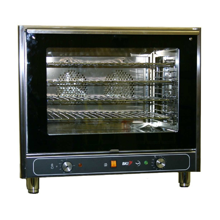
BKI
BKI MT-200 Service manual

Stalgast
Stalgast ClassicCook instruction manual
Blodgett
Blodgett ZEPHAIRE-200-G Installation operation & maintenance
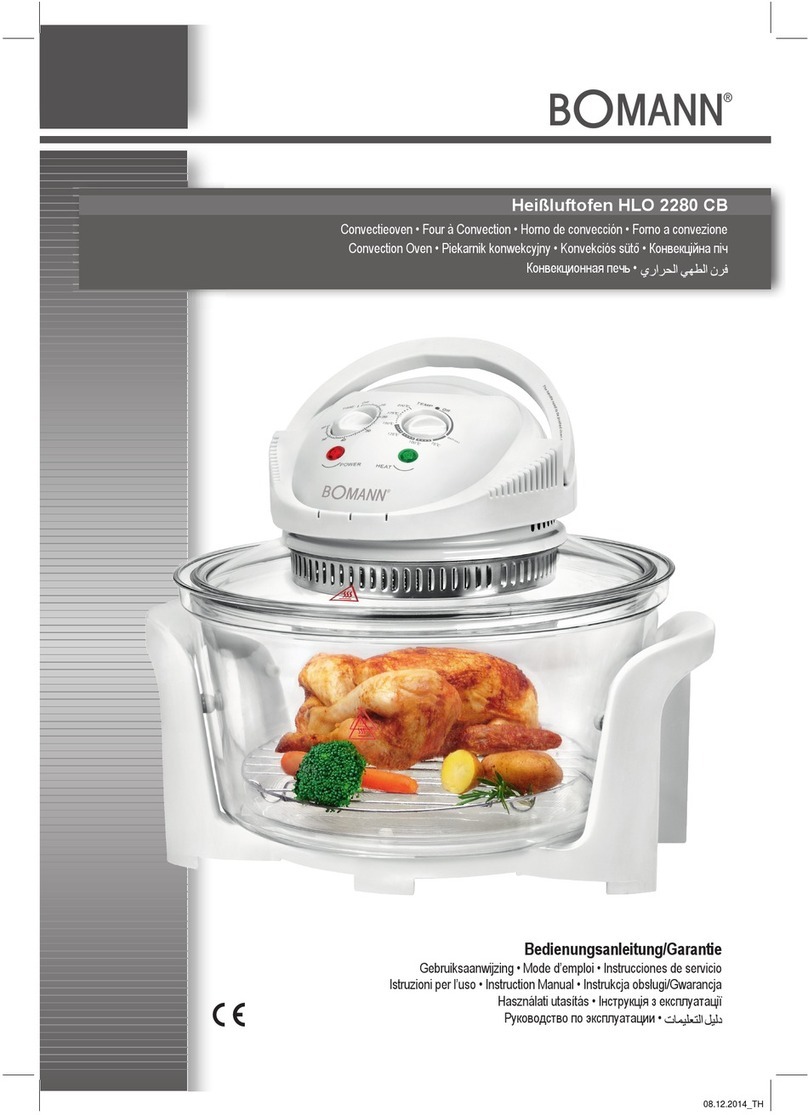
BOMANN
BOMANN HLO 2280 CB instruction manual
Cres Cor
Cres Cor Roast-N-Hold CO-151-FUA-12B Specification sheet
Fri-Jado
Fri-Jado GO Combi Diagnostics & faultfinding
Blodgett
Blodgett ZEPHAIRE-240E Installation operation & maintenance

Belshaw Brothers
Belshaw Brothers BACO25E Installation and operation manual
Rational
Rational CombiMaster Plus 61 Original operating instructions

Casselin
Casselin CFCV2 user manual
Vulcan-Hart
Vulcan-Hart VC5E Service manual
Black & Decker
Black & Decker Digital Advantage CTO6301 Use and care book

