Linear Satellite Radio User manual
DESCRIPTION
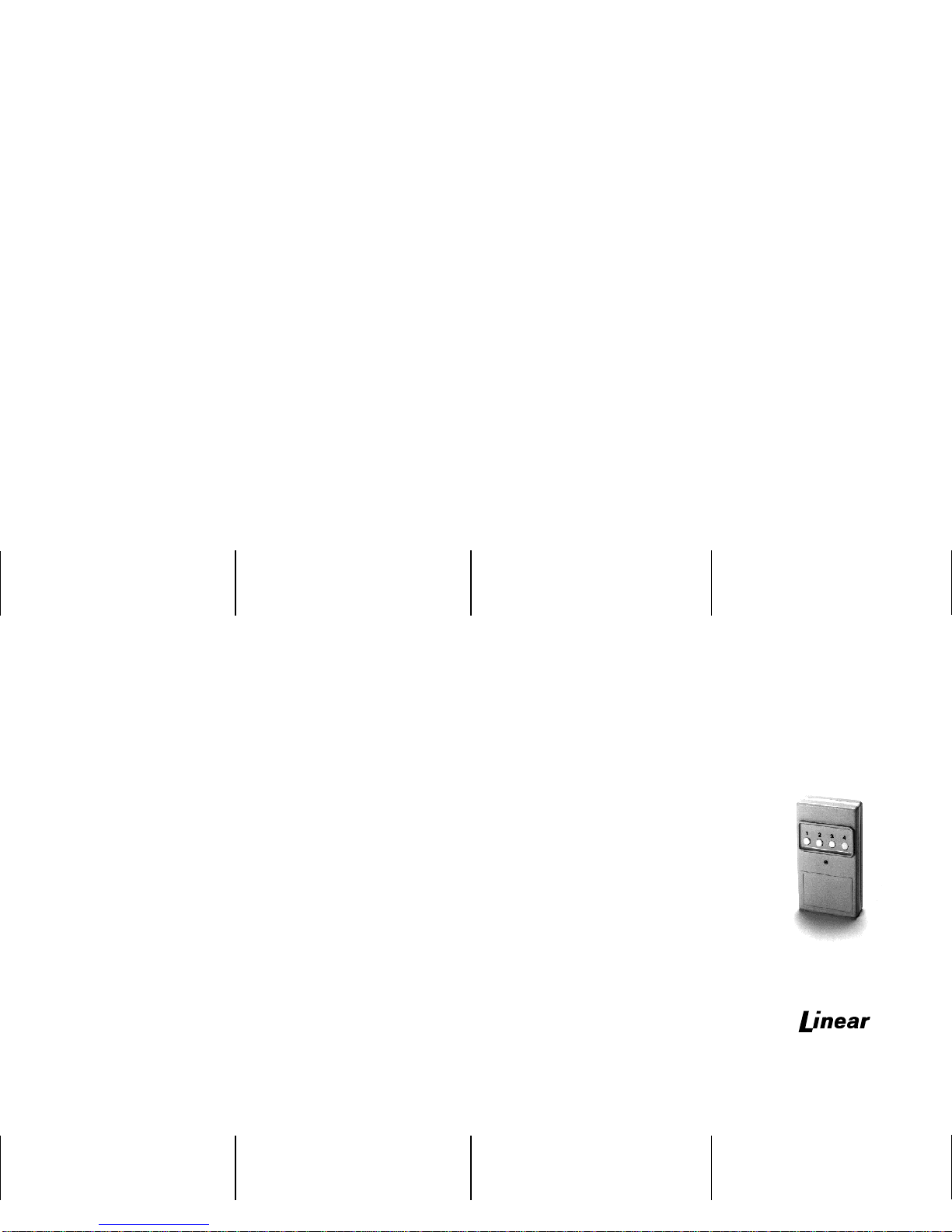
TheD-4Bisahandheldfour-channeltransmitter,
designed to perform fourseparate functions. this
attractive, lightweight transmitter, operating in
conjunctionwithfoursingle-channelreceivers,or
one multi-channel receiver, can perform a wide
variety of remote switching tasks.
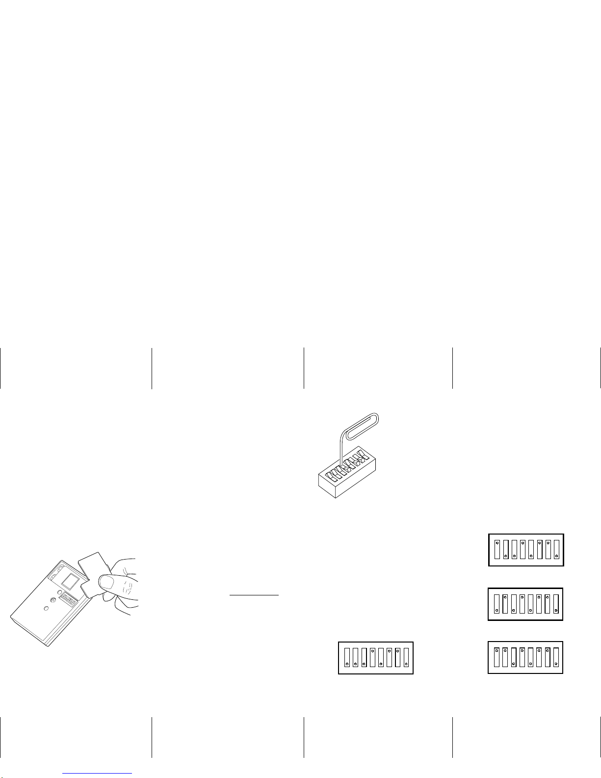
CODE SWITCH LOCATION
Thedigital codingswitchis attachedto thecircuit
boardinside thetransmitter.Itislocated beneath
the small access door on the back of the case
(see Figure 1). To reach the coding switch and
the 9-volt battery, gently pry open the access
door and lift it off.
CAUTION:
Transmitters and receivers should be
recoded by the installer prior to
installation.
In order to avoid the possibility of duplicating
codes in adjacent systems, factory set codes
should not be used. In addition, among the valid
codes available, four other should not be used
because they, also, are too often duplicated.
These include: (1) all keys set to ON; (2) all keys
set to OFF; (3) keys set in alternating ON/OFF
positions;and (4) keyssetinalternating OFF/ON
positions.
CODE SETTING FOR FOUR
SINGLE-CHANNEL RECEIVERS
Following is the procedure for coding four
single-channel receivers to a D-4B transmitter.
Use a paper clip or other pointed object (except
a pencil or pen) to set the keys on the digital
coding switches to the code you select -
rememberthepreviouscautionaboutcoding. Do
not use a pen or pencil; the ink or graphite may
contaminate the switch keys. Note that the D-4B
and each receiver has an eight-position
dipswitch (see Figure 2). The ON/OFF code
selected on keys 3-8 in the transmitter must
matchexactlywiththeON/OFFcodeselected
on keys 3-8 in each receiver. Set keys to ON
or OFF positions from left to right (from numbers
3-8). In the example shown in Figure 2, keys 4,
6 and 7 are set to ON; keys 1, 2, 3, 5, and 8 are
setto OFF. Keys 1 and 2in the transmitter are
not connected, they can be set in any
position.
Set each receiver’s switch keys 1 and 2 as
follows:
Receiver #1: Switch 1 OFF, switch 2 OFF (see
Figure 3)
Receiver #2: Switch 1 ON, switch 2 OFF (see
Figure 4)
Receiver #3: Switch 1 OFF, switch 2 ON (see
Figure 5)
Receiver #4: Switch 1 ON, switch 2 ON (see
Figure 6)
Each button on the D-4B will now activate a
separate receiver.
NOTE:
Mount receivers at least 10 feet apart
from each other.
CODE SETTING FOR
FOUR-CHANNEL RECEIVERS
To code a D-4B transmitter with a four-channel
receiver, procede as follows:
Set keys 3 through 8 in the transmitter to
correspond exactly to keys 3 through 8 in the
receiver. Matching these keys completes the
coding procedure required to activate the four
channels. Their functions are programmed to
access channels 1 through four corresponding
with buttons 1 through 4 onthe D-4B transmitter.
CODE SETTING FOR
EIGHT-CHANNEL RECEIVERS
TocodeaD-4Btransmitterwithaneight-channel
receiver, procede as follows:
Set keys 4 through 8 in the transmitter to
correspond exactly to keys 4 through 8 in the
receiver.
Forthetransmittertoactivatechannels1through
4 of the eight-channel receiver, set key 3 in the
transmitter to OFF.
Forthetransmittertoactivatechannels5through
8 of the eight-channel receiver, set key 3 in the
transmitter to ON.
Figure 1. Removing the Battery/Coding Access
Door
5
8
7
6
1
4
3
2
O
F
F
O
N
Figure 2. Example
Digital Coding
Switch
O
N
O
F
F
1 2 3 4 5 6 7 8
Figure 3. Receiver #1 Coding
O
N
O
F
F
1 2 3 4 5 6 7 8
Figure 4. Receiver #2 Coding
O
N
O
F
F
1 2 3 4 5 6 7 8
Figure 5. Receiver #3 Coding
O
N
O
F
F
1 2 3 4 5 6 7 8
Figure 6. Receiver #4 Coding
CHECKOUT AND TEST
After coding the D-4B transmitter and receiver,
the units should be tested as a system.
NOTE:
The receiver should be powered as
described in the Code Setting and
Installation Instructions pamphlet
enclosed with the receiver. Provision
should be made (with a meter or sounder)
to detect that the correct receiver output
is activated when a signal is received
from the D-4B transmitter.
To test the transmitter, perform the following
steps:
STEP 1: Move the transmitter at least six feet
away from the receiver and press a pushbutton.
Receiver activation indicates that the transmitter
is operating properly and that the
transmitter/receiver’s digital codes are correctly
matched.
NOTE:
The transmitter transmits continously
with any button depressed. The red LED
lights during transmission to indicate
batery condition.
STEP 2: Operate the transmitter from various
locations. This will help to locate possible null
areas where structural steel, and/or certain
obstacles may interfere with transmission.
Ifthe transmitterfailstoactivatethereceiver, first
check the coding switches to see that the switch
keys in the transmitter and receiver are properly
matched. Next, check the battery and replace it
if it is week. Although the battery should last for
a year with normal use, it is good practice to
install a new battery every six months.
LINEAR LIMITED WARRANTY
This Linear product is warranted against defects
in material and workmanship for twelve (12)
months. The Warranty Expiration Date islabeled
on the product. This warranty extends only to
wholesale customers who buy direct from
Linear or through Linear’s normal distribution
channels. Linear does not warrant this
product to consumers. Consumers should
inquire from their selling dealer as to the nature
of the dealer’s warranty, if any. There are no
obligations or liabilities on the part of Linear
corporation for consequential damages
arising out of or in connection with use or
performance of this product or other indirect
damages with respect to loss of property,
revenue, or profit, or cost of removal,
installation, or reinstallation. All implied
warranties, including implied warranties for
merchantability and implied warranties for
fitness, are valid only until Warranty Expiration
Date as labeled on the product. This Linear
Corporation Warranty is in lieu of all other
warranties express or implied.
For warranty service on Linear equipment return
product, at sender’s expense to:
Linear Corporation
5957 Landau Court
Carlsbad, CA 92008
Attention: Repairs Department
IMPORTANT !!!
Linear radio controls provide a reliable
communications linkand fillan importantneedin
portable wireless signalling. However, there are
some limitations which must be observed.
✶For U.S. installations only: The radios are
required to comply with FCC Rules and
Regulations as Part 15 devices. As such,
they have limited transmitter power and
therefore limited range.
✶Receivers may be blocked by radio signals
that occur on or near their operating
frequencies, regardless of code settings.
✶Areceivercannotrespondtomorethanone
transmitted signal at a time.
✶Infrequently used radio links should be
tested regularly to protect against
undetected interference or fault.
✶A general knowledge of radio and its
vagariesshould begainedprior toacting as
a wholesale distributor or dealer, and these
facts should be communicated to the
ultimate users.
Copyright © 1989 Linear Corporation 203983 A
D-4B
FOUR-CHANNEL
DIGITAL TRANSMITTER
Code Setting
Instructions
2055 Corte Del Nogal
Carlsbad, CA 92009
(619) 438-7000 •(800) 421-1587
CA (800) 321-1845 •FAX (619) 438-7043
Customer/Technical Service: (800) 392-0123
A NORTEK COMPANY
Other Linear Radio manuals


