RCA Radiola 21 Operating and maintenance manual

RCA
Radiola 21 and Radiola 22
SERVICE NOTES
RCA Radiola 21
First Edition—30M Copyright October 1929
RADIO-VICTOR CORPORATION OF AMERICA
233 BROADWAY, NEW YORK CITY
DISTRICT SERVICE STATIONS
BROOKLYN, N. Y. CHICAGO, ILL. SAN FRANCISCO. CAL.
Bldg. No. 19—168 - 39th St. 2001 West Pershing Road 274 Brannan St.
DALLAS, TEXAS ATLANTA, GA.
Santa Fe Bidg., Unit No. 2 150 Peters St.

PREFACE
Service goes hand in hand with sales. The well-informed RCA Authorized Dealer renders
service at time of sale in affording information as to proper installation and upkeep. Subsequent
service and repair may be required by reason of wear and tear and mishandling, to the end that RCA
Loudspeaker and Radiola owners may be entirely satisfied.
Obviously, this service can best be rendered by properly equipped service organizations having
a thoroughly trained personnel with a knowledge of the design and operation of RCA Loudspeakers
and Radiolas.
Such service organizations have been established by RCA Distributors, and RCA Authorized
Dealers are advised to refer any major work or replacement to their selected Distributors. Minor
replacements and mechanical and electrical adjustments may be undertaken by the RCA Dealer.
To assist in promoting this phase of the Dealer and Distributor's business the RCA Service
Department has prepared a series of Service Notes—of which this booklet is a part—containing
technical information and practical helps in servicing RCA Loudspeakers and Radiolas.
This information has been compiled from experience with RCA Dealers and Distributors'
service problems and presents the best practice in dealing with them. A careful reading of these
Service Notes will establish their value, and it is suggested they be preserved for ready reference.
In addition to supplying the Service Notes, the RCA Service Department maintains a corps of
engineers who are qualified to render valuable help in solving service problems. These engineers
call upon the trade at frequent intervals to advise and assist RCA Distributors in the performance of
service work.
Property of the Radio-victor Corporation of America. Confidential and to be used only by its Authorized
Distributors and Dealers in furnishing service in connection with itsapparatus
Copyright 1929—Radio-victor Corporation of America

CONTENTS
Page Preface …………………—-—-—————-——-—————-———-————-—2
Electrical and Physical Specifications-—-—-————-——-——————----———-—— 5
Introduction ——————-----—---——-——----——-——-———---—-————-—-—- 6
PART I—INSTALLATION
Antenna (Indoor or Outdoor)-----..—-7 Shields —————---—-—-….——---———-- 7
Ground ------------------------------------ 7 Batteries —————--—-———-———----—7
PART II—SERVICE DATA
Antenna System Failures----.-—------------- 7 Adjusting R. F. Line-up Condensers--------- 7
Radiotron Sockets and Prongs----------.----- 7 Service Data on Reproducer Unit-------..----- 7
Broken Condenser Drive Cord———----- 7 Service Data Charts—--——-————….—8-9
PART HI—ELECTRICAL TESTS
Testing Condensers ——------—------—---- 10 Socket Voltages Radiola 21 or 22---—------ 10
Voltage Readings -—-—-——--—.——.—10 Radiola 21 or 22 Continuity Tests-—------- 11
Continuity Test Charts ————— 13-15
PART IV—MAKING REPLACEMENTS
Removing Chassis from Cabinet of Radiola 21 16 Removing Reproducer from Radiola 22-—--- 16
Removing Receiver Assembly from Radiola 22 16 Replacing R.F. Line-up Condensers- -——— 16
ILLUSTRATIONS
RCA Radiola 21 ------------------------------------- 1 Schematic Circuit Diagram of Radiolas 21 and
Rear Interior Cabinet View of Radiola 22 ----- 4 22 Receivers-----------------------------------—--——----—11
Top View of Receiver Chassis------------------ 5
Sub-Chassis View of Receiver------------------ 6
Rear view with shields removed ------------------ 7 Radiola 22 Battery Cable and External Connections ---- 12
Internal Connections of A.P. Coupling Unit---- 10 Wiring Diagram and Color Code-—--------------- -——— 14
3

Figure 1—Rear interior cabinet view of Radiola 22
4
RECEIVER
ASSEMBLY
REPRODUCER
UNIT
ANTENNA
AND
GROUND
LEADS
BATTERY
CABLE

RCA RADIOLAS 21 and 22
SERVICE NOTES Prepared by RCA Service
Department
STAGE SHIELDS
VOLUME CONTROL LOCAL-DISTANT SWITCH OPERATING SWITCH
Figure 2—Top view of receiver chassis showing location of some parts
ELECTRICAL AND PHYSICAL SPECIFICATIONS
Type of receiver—Screen Grid Tuned R.F. Battery.
Recommended Antenna Length—35—60 feet.
Type of Filament Power—Storage Battery or Eliminator.
Type of Plate and Grid Power—"B" and "C" Batteries or
Eliminator.
Number and Type of Tubes—Two UX-222, 2UX-112A,
1 UX-112A or UX-171A—Total 5.
Number of R.F. Stages—Two.
Type of Detector—Grid condenser and leak.
Number of A.F. Stages—Two.
Type of Loudspeaker (R22 only)—Magnetic.
5
RADIOTRON SOCKETS
FOR A.F. STAGES
STATION
SELECTOR DIAL
Height ........
Depth .........
Width ........
Weight, alone . .
Weight, packed
R21
10.5 inches
10.0 "
20.5 "
27 Ibs.
40 Ibs.
R22
40.5 inches
22.0 "
21.5"
44 Ibs.
105 lbs.

INTRODUCTION
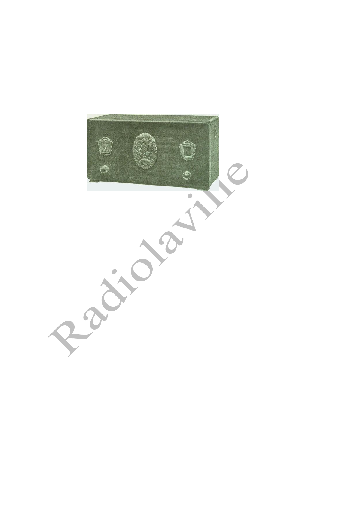
RCA Radiolas 21 and 22 are battery operated screen grid radio receiving sets. Radiola 21 is a table model and
Radiola 22 is a console model employing the same receiver chassis and the mechanism of RCA Loudspeaker 100B.
RCA Screen Grid Radiotrons UX-222 are employed as radio frequency amplifiers, Radiotrons UX-112A as the
detector and first audio and UX-112A or UX-171A as the power stage. The choice of the power tube is left to the
customer, as different tubes may be desirable for different output requirements. The different battery requirements
may also have a bearing on the choice, as the UX-H1A requires more plate and bias batteries to
obtain advantage of its greater output.
The sensitivity and selectivity of these Radiolas is sufficient for excellent reception.
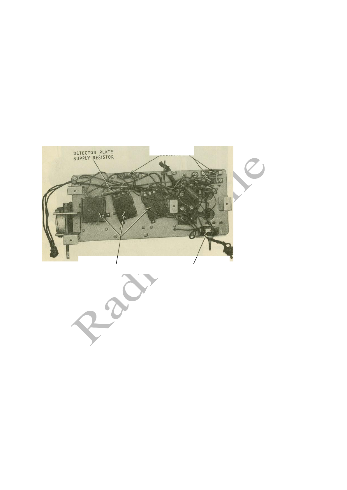
The fidelity is very good. Figure 1 illustrates a rear interior cabinet view of Radiola 22, Figure 2 top view of receiver
chassis, Figure 3 sub-chassis view of receiver, and
Figure 4 a view of the receiver with shields removed.
Figure 3—Sub-chassis view of receiver
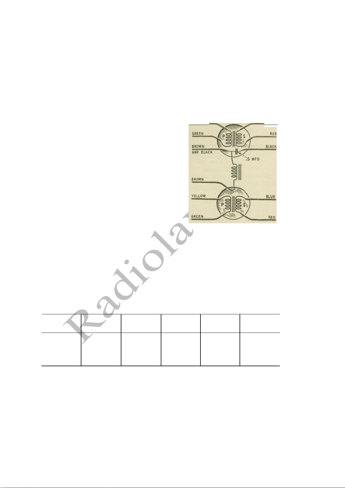
Circuit features, see Figure 6, of these Radiolas are:
(a) Screen grid battery receiver giving sensitivity and selectivity comparable to-
that obtained with A.C. type screen grid receivers.
(b) Circuit consists of two tuned R.F. stages, tuned grid leak type detector, first:
audio stage and second audio stage employing a choice of power tubes.
(c) Local-distant switch provides best reception on both loud and weak signals. At the local position a .00023
mfd. condenser is connected from the antenna connection to ground. This condenser or when the switch
is at "distant," the antenna to ground capacity, causes the circuit to resonate in the broadcast band at
about 700 K.C., and thereby brings up the sensitivity of the low frequency end. The result is that the
receiver has about equal sensitivity throughout the tuning range.
(d) The use of screen grid tubes together with proper shielding, eliminates the necessity of neutralizing or other
methods of stabilizing.
(e) The volume control varies the voltage on the screen grid of the two R.F. tubes. This provides a smooth
means of control which, together with the local-distant switch, provides a positive cut-off even on loud
local stations.
6
FILAMET
RESISTORS
BY-PASS CONDENSERS
VOLUME CONTROL

(f) The operating switch disconnects the filament battery and the "B" voltage to the volume control. This
prevents unnecessary "B" battery consumption when the receiver is not in use.
(g) A fixed regenerative detector gives added sensitivity to that circuit with a resulting gain in over-all
sensitivity. This does not require any adjustment during operation.
PART I—INSTALLATION
Information on the various points dealing with installation as listed below can be obtained by referring to the
Service Notes or Instruction Books mentioned. This information has been repeatedly published in past issues of
Service Notes, and the average service man is probably so familiar with it, that further details are unnecessary.
The Radiola 22 has two red wood screws to hold the reproducer unit during shipment. Be sure that these
are removed as otherwise acoustic howling may result.
Antenna (Indoor or outdoor).—See R-44 and 46 Service Notes.
RADIOTRON SOCKETS FOR, 1st
and 2nd R.F. AND DETECTOR.
Figure 4—View of receiver with shields removed
Ground.—See R-44 and 46 Service Notes.
Shields.—See R-44 and 46 Service Notes.
Batteries and Connections.—See R-21 or 22 Instruction Book.
PART II—SERVICE DATA
Service data on the following subjects can be obtained from the Service Notes mentioned below:
Antenna system failures.—See R-44 and 46 Service Notes.
Radiotron sockets and prongs.—See R-44 and 46 Service Notes.
Broken condenser drive cord.—See R-44 and 46 Service Notes.
Adjusting R.F. line-up condensers.—See R-44 and 46 Service Notes.
Service data on reproducer unit.—See R-100A or R-100B Service Notes.
7
INTERSTAGE
COUPLING UNIT

SERVICE DATA CHART
The following service data chart indicates various troubles by their symptoms and gives the specific remedy
necessary.
Indication Cause Remedy
Defective Radiotrons
Poor antenna system
Run-down batteries
Line-up condensers put of adjustment
Defective parts in receiver
Defective loudspeaker
Test and replace any defective Radiotrons
Install antenna as suggested in Part I
Check voltage of all batteries including any
eliminator if used. Unless the voltages are within
the limits given in Part III, Section 2, batteries
should be replaced. If it is the storage battery it
should be charged until gassing lasts for 1 hour.
If a trickle charger is being used possibly the rate
is not sufficiently high for the service the
receiver is giving. The remedy is to increase the
charging rate
Adjust line-up condensers as described in R-44 and
46 Service Notes
Check by means of continuity test and make any
replacement necessary
Check by using- another loudspeaker known to be
in good operating condition and make any
replacement necessary
Defective Radiotrons
Defective interstage A.F. transformer, output
choke, output condenser or other parts
Receiver oscillation
Test and replace any defective Radiotron
Check parts by means of continuity test and make
any replacement necessary
Should the Radiolas oscillate, all signals will be
weak, distorted and accompanied by a whistle.
See section on "Oscillation" for remedies
8
No Reproduction
Defective Radiotrons
Defective Operating Switch
Defective Volume Control
Wrong battery connections
Run-down batteries
Defective local-distant switch
Defective parts in receiver
Defective loudspeaker
Replace defective Radiotrons
Replace defective operating switch
Replace defective volume control
Connect battery correctly. Complete instructions are
given in R-21 or 22 Instruction Book
Replace "B" and "C" batteries if low. Charge
storage battery if necessary.
Replace defective local-distant switch.
Check by means of continuity tests and make any
replacement necessary
Repair any defect in loudspeaker
Low Volume
Distorted Reproduction

SERVICE DATA CHART—Continued
Indication Cause Remedy
An audio grunt or howl may be caused in
Radiola 22 by reversed output leads- to the
loudspeaker
Oscillation
By-pass condenser
Radiotrons
Audio system
'
Connect loudspeaker leads as shown in Figure 7
Receiver oscillation will cause a whistle when the
receiver is tuned through a broadcasting station
carrier wave. See section on "Oscillation" for
remedies
An open in any of the bypass condensers may
cause an audio howl
Vibrating elements in Radiotrons will cause a
gradually developing howl. See section under
"Acoustic Howl"
A defective audio system may cause a howl
Shields not in place or -not making good
contact
Local-distant switch not grounded
Shield contact clips- not clamping condenser
shaft properly
Open by-pass condenser
Defective Radiotrons
Place the tube shield over sockets 1 and 2 and the
stage shields over sockets 2 and 3. If oscillation
does not stop clean points of contact between
base and all shields
Ground local-distant switch properly
Bend shield contact clips so that a good, firm
contact is made to the condenser rotor shaft
An open by-pass condenser or one improperly
connected may cause oscillation. Check and
replace if necessary
A defective Radiotron UX-222 may cause
oscillation. Interchanging with one known to
l»e in good condition will remedy the trouble
9
Distorted
Reproduction
Defective batteries-
Defective loudspeaker
Check battery voltages and discard any with
readings not in the limits given in Part III, Section
2, Charge storage battery if necessary
Check with a loudspeaker known to be in good
operating condition. Make any
repairs necessary
Acoustic Howl
Radiotron selection
Loudspeaker mounting
Loudspeaker position
Interchange Radiotrons, especially the detector
Check mounting of loudspeaker of Radiola 22 and
make sure it is properly supported
Do not place loudspeaker too close to Radiola 21.
Increase its distance to the receiver or change the
relative angle between the loudspeaker and the
receiver
Audio Howl
Oscillation

PART Ill—ELECTRICAL TESTS
(1) TESTING CONDENSERS
Most of the condensers in Radiolas 21 and 22 can be tested by the continuity tests given in Part III, Section 3.
If further tests are desirable the large 1 mfd. condensers may be tested by charging them with the highest "B"
voltage available and then shorting their terminals with a screw-driver. An O.K. condenser will give a good. spark
when such a short is made. A leaky condenser will give no spark and a shorted condenser will give a spark when an
attempt is made to charge it.
Small condensers may be click tested for shorts or conveniently replaced by new-ones to check on their
operating condition.
(2) VOLTAGE READINGS
The following voltages taken at the sockets are correct for
batteries when new. A 25 per cent drop is permissible before
renewal is necessary. Individual batteries may be tested by dis-
connecting entirely and reading with a voltmeter. The "B"
batteries should be discarded when their voltage is less than 34
volts per block. The "C" batteries should be renewed with the
"B" batteries. A storage "A" battery requires charging when the
voltage is below 5.4 for a battery or 1.8 per cell under load.
SOCKET VOLTAGES
RADIOLA 21 OR 22
Radiotron UX-171A used in last stage with 135 volts plate
supply. For other power tubes or plate voltage the change will be
in last socket Figure 5—Internal connections of A.F. only, all
other voltages remaining the same.
VOLUME CONTROL AT MINIMUM
Socket No.
Filament Volts
Filament to
Control Grid Volts
Filament to
Screen Grid Volts
Filament to
Plate—Volts
Plate Current
Millamperes
1
3.2
1.6
0
135
0
2
3.2
1.6
0
135
0
3
5.0
—
—
45
3.5
4
5.0
9
—
125
6.5
5
5.0
27
—
130
15
10
YELLOW
BLUE
Figure 5—Internal connections of A.F.
Coupling Unit
YELLOW
BLUE

VOLUME CONTROL AT MAXIMUM
Socket No.
Filament Volts
Filament to Control
Grid Volts
Filament to Screen
Grid Volts
Filament to
Plate—Volts
Plate Current
Milliamperes
1
3.2
1.6
67
135
5.0
2
3.2
1.6
67
135
3.0
3
5.0
------
——
45
3.5
4
5.0
9
-------
125
6.5
5
5.0
27
——
130
15
Figure 6—Schematic circuit diagram of Radiolas 21 and 22 receivers
(3) RADIOLA 21 OR 22 CONTINUITY TESTS 1060
The following tests will show complete continuity for the receiver assembly of Radiolas 21 and 22.
Disconnect the antenna and ground leads, the cable connections to all batteries, and unscrew the pilot lamp.
A pair of headphones with at least 4^2 volts in series or a voltmeter with sufficient battery to give a good
deflection when connected across the battery terminals should be used in making these tests.
The resistance of the various circuits are also shown in the column titled, "Correct Effect." Checking the
resistance of the circuits adds an additional check on their correct functioning. This may be done by means of a direct
reading "Ohmmeter," a resistance bridge, or any of the methods shown in previous issues of RCA Service Notes.
The Radiotron contacts and socket numbers, the cable connections and color scheme are shown in Figures 7
and 8, and should be referred to when making these tests. Figure 5 illustrates the internal connections of the A.F.
coupling unit.
11
1059

Figure 7—Radiola 22 battery cable and external connections of receiver assembly and reproducer unit
11
OPERATIN6
SWITCH
TO GROUND TO ANTENNA
LOCAL-DISTANT
SWITCH
B+ PWR
B+AMP. 135 V.
B+ 67 V.
C-AMP. 9V.
C-PWR.
A-6V

CONTINUITY TEST CHART
Unscrew Pilot Lamp Before Making Test
Circuit
Test Terminals
Correct Effect
Incorrect Effect
Indication
Caused by
Grid
CG1 to Ground
Closed (3 Ohms)
Short
former Shorted tuning or trimming condenser
SG1 or SG2 to
B+67(Maroon) Vol.
Cont. at minimum
Closed (50,000
Ohms)
Open
Open volume control or connection
SG1 or SG2 to
B+67(Maroon) Vol.
Cont. at maximum
Closed (Short)
Open
Open connection or volume control arm
CG2 to Ground
Closed (3 Ohms)
Open
Short
Open Secondary of 2nd R.F. transformer
Shorted tuning or trimming condenser
G3 to Ground
Closed (4 Megs)
Open
Short
Open grid leak or secondary of 3rd R.F.
transformer
Shorted grid condenser and tuning or trimming
condenser
Stator tuning
condenser No. 3 to
Ground
Closed (3 Ohms)
Open Short
former Shorted tuning or trimming condenser
G4 to C—9 (Black
and Green)
Closed (5,500
Ohms)
Open
Open secondary of 1st A.F. transformer
G5 to C—Pwr
(B lack wit h Green
tracer)
Closed (5,500
Ohms)
Open
•
Open secondary of 2nd A.F. transformer
Plate
PI to B+135 (Maroon
and Red)
Closed (60 Ohms)
Open
Open primary of 2nd R.F. transformer
P2 to B+13S (Maroon
and Red)
Closed (60 Ohms)
Open
Open primary of 3rd R.F. transformer
P3 to B+135 (Maroon
and Red)
Closed (31,100
Ohms)
Open 1,100 Ohms
Open regenerative coil, primary of 1st A.F.
transformer or 30,000
ohm resistor Shorted 30,000 ohm
resistor
P4 to B+13S (Maroon
and Red)
Closed (1,000
Ohms)
Open
Open primary of 2nd A.F. 'transformer
P5 to B + Pwr (Red)
Closed (550 Ohms)
Open
Open output choke
P5 to output jack with
insulating bushing
Open
Closed
Shorted .5 mid, output condenser
13

Figure 8—Wiring diagram showing color code and connections

CONTINUITY TEST CHART—Continued Unscrew Pilot
Lamp Before Making Test
Circuit
Test Terminals
Correct Effect
Incorrect Effect
Indication
Caused By
Filament
—Fl to Ground
Closed (6.5 Ohms)
,0pen Short
Open UX-222 filament resistor or connection
Shorted .1 mfd. condenser
—P2 to Ground
Closed (6.5 Ohms)
Open
Short
Open UX-222 filament resistor or connection
Shorted .1 mfd. condenser
—F3 to Ground
Closed (Short)
Open
Open connection
—F4 to Ground
Closed (Short)
Open'
/ Open connection
—P5 to Ground
Closed (Short)
Open
Open connection
+F1 to +A (Yellow)
Closed (1.55
Ohms)
Open
Open 1.55 ohm resistor or connection
+F2 to +A (Yellow)
Closed (1.55
Ohms)
Open
Open 1.55 ohm resistor or connection
+F3 to +A (Yellow)
Closed (1.95
Ohms)
Open
Open 1.95 ohm resistor or connection
+F4 to +A (Yellow)
Closed (1.95
Ohms)
Open'
Open 1.95 ohm resistor or connection
+F5 to +A
(Yellow)
Closed
(1.55 Ohms)
Open
Open 1.55 ohm resistor or connection
Misc.
Antenna to ground
(Switch at "distant"
position)
Closed (30 Ohms)
Open
Open connection, antenna loading coil, or
primary of first R.F. transformer
B+67 (Maroon) to
A—(Black with
Yellow tracer) (Close
op. sw.).
Closed (50,000
Ohms)
Open
Open volume control
—Fl to B+13S
(Maroon and Red)
Open
Closed
Shorted .1 mfd. condenser
—F2 to B+ 135
(Maroon and Red)
Open
Closed
Shorted :1 mfd. condenser
B+135 (Maroon and
Red) to ground
Open
Closed
Shorted 1 mfd. condenser
P3 to —F3
Open
Closed
Shorted 1 mfd. condenser or .0012
mfd. condenser
G4 to —F4
Open
Closed ,
Shorted .00016 mfd. condenser
SG1 to —Fl
Open
Closed
Shorted 0.1 mfd. condenser
SG2 to —F2
Open
Closed
Shorted 0.1 mfd. condenser
15

PART IV—MAKING REPLACEMENTS
The various assemblies and parts of Radiolas 21 and 22 are readily accessible and replacements can be
easily made. Figure 3 illustrates the receiver chassis and Figure:
1 the rear interior cabinet view of Radiola 22. The following procedure gives the correct method for removing the
various assemblies from their cabinets.
(1) REMOVING CHASSIS FROM CABINET OF RADIOLA 21
To remove the receiver chassis from the cabinet .of the Radiola 21, proceed as. follows:
(a) Release the local-distant switch a id the operating switch from their respective
escutcheon plates. This is best done by removing the wood screws that hold .-the escutcheon and then
releasing the switch from the escutcheon by twisting its mechanism with the hand. This eliminates the
possibility of marring the collar of the switches with pliers or other tools.
(b) Remove the four machine screws at the bottom of the cabinet that holds. the chassis in place.
(c) Remove the volume control and station selector knobs from their respective shafts by merely pulling
them off.
(d) The chassis may now be lifted clear of the cabinet and placed in a position convenient for work.
(2) REMOVING R-22 RECEIVER ASSEMBLY
To remove the receiver assembly of Radiola 22 proceed as follows:
(a) Release the operating switch and local distant switch by removing their escutcheons and releasing the
switch collar. Replace the escutcheons temporarily.
(b) Remove the station selector and volume control knobs.
(c) Release the antenna and ground leads and the battery cable. Remove the loudspeaker connections from
the pin jacks on the receiver assembly.
(d) Remove the four machine screws that hold the chassis to the shelf. It may now be lifted clear and placed
in a position convenient for work. After the completion of all repairing replace it in the reverse
manner of that used to' remove it.
(3) REMOVING R-22 REPRODUCER UNIT
To remove the R-22 reproducer unit proceed as follows:
(a) Release the two loudspeaker leads from the receiver chassis at the output pin' jacks.
(b) Remove the eight screws that hold the reproducer unit mounting felt to the baffle board. The unit
together with its felt mounting may be lifted clear and placed in a position convenient for work. After
all work is completed it should be replaced in the reverse manner of that used to remove it.
(4) REPLACING R.F. LINE-UP CONDENSERS
The correct procedure for replacing the R.F. line-up condensers is given in the Radiola 44 and 46 Service
Notes and should be followed when making a replacement of this kind.
16
This manual suits for next models
1
Table of contents
Other RCA Radio manuals

RCA
RCA RIR205 - Infinite Radio Tabletop Internet User manual

RCA
RCA EZDVD1 - Memory Maker And EZ201 Small Wonder 60 Minute Camcorder... User manual

RCA
RCA RDR6350 User manual

RCA
RCA BR200D-U1 User manual

RCA
RCA 7T Manual

RCA
RCA EZDVD1 - Memory Maker And EZ201 Small Wonder 60 Minute Camcorder... User manual

RCA
RCA Radiola 26 User manual

RCA
RCA RDR260 Series User manual

RCA
RCA BR200DV User manual

RCA
RCA RIR200 User manual