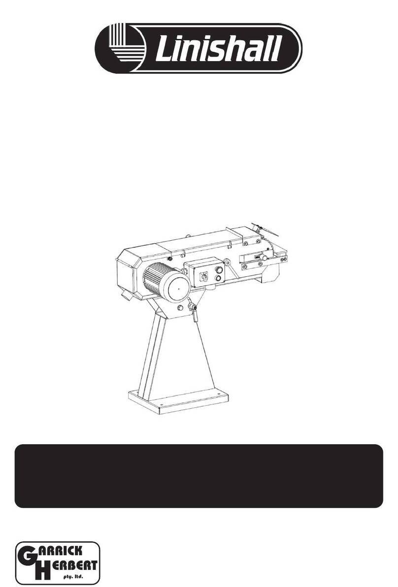
Linishall 1220/100/P1 Operation instructions

HEAVY DUTY LINISHER
USER’S OPERATING MANUAL & SERVICE INSTRUCTIONS
MODEL - 1220/100/P1
460 - 462 The Boulevarde, Kirrawee, NSW 2232
(P) (02) 9545-6633 (E) [email protected]
garrickherbert.com.au
CAUTION
Read instruction manual before operating any machinery

PG 2
FOREWORD
These instructions have been created by the manufacturer
and are IMPORTANT for correct use and operation of this machine.
The machine is equipped with various safety devices protecting both the operator
and the machine for its intended use. The operation manual should be read and
understood by anyone intending to use the machine. Errors made in the course
of installation as well as during operation itself will void warranty.
Do not try therefore to put the machine into operation before
you have read all instructions supplied and understood all its
functions and working procedures.
Certain information or drawings may not be intended directly for this machine
purchased by you as these instructions contain any information for various variants of
this type made by our company. By comparing the respective part of the instructions
with a particular machine you will nd out whether or not they correspond to each other.
The manufacturer reserves the right to make partial alterations within
continuous technical machine development.

USE OF THE MACHINE
Purpose of the machine
Metal belt sanders are mainly used to conduct surface polishing and grinding
of metal and non-metal parts, to enhance the roughness and glossiness
of spare parts surface. The machine performance is very ecient for grinding.
It is an ideal substitute for polishing machines.
The machine must not be handled by children or inexperience persons.
Workers qualications
Only an expert, skilled in the eld of metal-machining or a worker instructed
and trained by such expert may operate the machine. While working on the machine
the operator must be familiar with these instructions and comply with any safety rules,
regulations and provisions in force in the respective country.
Working environment
The machine must be operated in a workshop environment,
Temperature MUST not exceed +40℃and does not drop below +5℃.
The relative humidity of ambient is from 30% to 95%, non-condensing.
The height above the sea level is up to 1000m.
Storage and transportation temperature: -25~55℃
The environment classication
Danger of inammable dust re.
PG 3

SAFETY INSTRUCTIONS
General
This machine is equipped with various safety devices protecting both the operator
and the machine. Nevertheless, this cannot cover all safety aspects and therefore the
operator, before putting the machine into operation. Furthermore, the operator must
also take into account other aspects of danger relating to the surrounding conditions
and material.
Basic safety requirements
Before connecting the machine to the mains, make sure that all safety items are in their
active positions and check their functioning. If it is necessary to remove the doors or
protective covers, turn o the switch and disconnect the plug from its socket.
Kick-back catchers must be freely movable and their functioning must be checked regularly,
even several times a day.
Do not connect the machine to the mains while the door or protective cover is removed.
In order to avoid improper operation, get acquainted with the location of switches before
switching the machine on.
Remember the position (location) of the emergency stop switch so that you can use it
promptly at any time.
Be careful and do not touch any switches while the machine is being operated.
Do not touch any rotating tool by hands or with any other object under any circumstances.
In the case that you are not going to work on the machine, turn o the machine by the switch
and disconnect the plug from the supply socket.
Before cleaning the machine, switch o the machine and disconnect the plug of the machine.
Before doing any maintenance work inside the machine, switch o the machine and
disconnect the plug of the machine.
Do not alter the machine in any manner which might cause any risk to safety and operation.
If you have any doubts on the procedure, please contact a qualied professional for advice.
Do not neglect performance of regular inspections in accordance with the instructions for use.
Check and make sure that no disturbances occur on the machine caused by the user.
After the work is nished, adjust the machine so that it is ready for another series of operations.
Should a failure in power supply occur, switch o the machine immediately
Do not paint, Dirty, cause any damage to, alter or remove safety plates. If they become
illegible or lost, contact the manufacturer and replace the plates.
Keep work area clear. Cluttered areas and benches cause injuries.
Consider work area’s environment. Do not expose tools to rain. Do not use tools in damp or wet
location. Keep work area well lit. Do not use tools in the presence of ammable liquids or gases.
PG 4

Clothes and personal safety
Experience shows that injuries are caused by various personal articles, e.g. rings, watches,
bracelets, bow tie etc. Therefore, take them o before starting to work, button the sleeves,
take o a tie, which may be caught with various parts of the working machine. Wear hair
protection and fasten hair properly to avoid catching by moving part. Wear suitable tight
clothing, shoes recommended or prescribed by labour-safety regulations of all countries.
Wear safety outt (goggles, apron, safety shoes, hearing protection etc.).
In the case of any obstacles above your head – in the working area - wear a helmet.
Always wear a protective mask while machining any material that produces dust while being used.
Never wear any loose working clothes.
Do not work on the machine under inuence of drugs, alcohol, and or tiredness.
Safety regulations for operators
Do not put the machine into operation before you get acquainted with the contents of
the instructions for use.
Make sure that electric cables are not damaged so that injuries caused by electric current
leaking (electric shocks) are avoided.
Check regularly that safety covers are mounted properly and that they are not damaged.
Repair damaged covers immediately or replace with other ones by a qualied person.
Do not put the machine into operation with the cover removed.
Never use any tools that are distorted, broken or blunt.
Always use the tool suitable for the work given, which corresponds to the machine
specications. The tools, cutter blocks, must be in accordance with EN 847-1.
Replace blunt tools as soon as possible, as blunt tools may cause injuries or damage.
Never use the tools at speeds higher than their recommended
rated speeds by the respective manufacturer.
Stop all functions of the machines before replacing tools
and pull out the plug from the supply socket.
Do not remove or interfere otherwise in safety devices such as covers, limit switches.
While handling parts that you are not familiar with, ask for help from a qualied person.
It is not recommended to work on the machine during a storm.
PG 5

Safety regulations for maintenance
Maintenance and repair must be performed by a qualied person.
Do not do any maintenance work before you get acquainted with these
instructions and understood in detail.
Before you start to perform any maintenance work, always turn o the switch
and pull out the plug from supply socket. A possibility of accidentally
putting the machine into operation by another person is thus avoided.
Any maintenance work on electric parts of the equipment must
be done by a qualied person only.
Even if the machine is stopped, the power supply is not disconnected.
Always disconnect the plug from supply socket.
Do not clean the machine or its peripheral devices even if the machine is completely
out of operation, unless the plug has been disconnected from supply socket.
Keep your ngers at a distance from belts and belt pulleys.
While replacing electrical parts of the equipment, turn o the switch and disconnect
the plug from supply socket. Faulty parts should be replaced only with products
having the same specications as the original ones.
Do not remove or interfere otherwise in safety devices such as covers, limit switches.
Do not switch the machine on before all covers removed for the
purposes of maintenance are put in their places again.
Always keep the maintenance area including the working place clean.
Any maintenance work must be done by a qualied sta in
accordance with the instructions issued by the machine manufacturer.
Read the instruction manual for maintenance carefully and completely.
For replacement of parts, only replace with the original
type and that comply with standards.
Use only specied kinds or lubricating oils and grease or those equivalent to them.
If any belt in the set of belts used gets longer than the limit prescribed,
replace the whole set completely.
Do not use compressed air to clean the machine or to remove chips.
Always check the results while a responsible person is present.
PG 6

Safety regulations for place of work
Always ensure a sucient working area and free access to the machine.
Put tools and any other obstacles in the place designated for this purpose,
in a distance from the machine.
Ensure sucient lighting in the working area which will not create shadows
or cause the stroboscopic eect. For safe and quality work the hygienic
standards specify the minimum intensity 500 lux.
Never put any tools or any other objects on working tables or covers.
Always keep the working area clean and tidy.
Always ensure a sucient working area and free access to the machine.
Put tools and any other obstacles in their place in a distance from the machine.
Never put any tools or any other objects on working tables or covers.
Always keep the working area clean and tidy.
TRANSPORT AND STORAGE
While transporting or handling the machine, be most careful and let this
activity be done by qualied person especially trained for this kind of activity.
While the machine is being loaded or unloaded,
make sure that no person or object gets pressed by the machine!
Do not enter the area under the machine lifted
by a crane or a high-lift trolley!
During transporting or storing the machine, means must be taken to
protect the machine against excessive vibrations and humidity.
It should be stored in a shelter at temperatures ranging from -25°C to 55°C.
As standard, the machine is wrapped up in a plastic tray and is transported this way.
Machinery may be packed in a robust wooden box.
PG 7

TECHNICAL SPECIFICATIONS
PG 8
A. Spark Trap
B. Eye Shield
C. Contact Wheel
D. Belt Tracking Adjustment Knob
E. Belt Tension Release Lever
F. Start Switch
G. Motor
H. Dust Port
KNOW YOUR MACHINES
NAME SM100
Dimensions of sander (mm) 100X1220
Granularity of belt sander 36-80
Linear velocity (m/s) 19
Motor power (kW) 1.5
Speed (r.p.m) 2860
Belt sanding table 280X100
Contact disc ø / w 127/100

PG 9
Specications concerning noise of the device
Level of noise A in the place of
operation (LpAeq)
No-load LpAeq =81.7 dB(A)
Load LpAeq =89.5 dB(A)
Level of acoustic power A (LWA) No-load LWA = 94.5 dB(A)
Load LWA = 103 dB(A)
OPERATING CONDITIONS FOR NOISE MEASUREMENT
COMPLY WITH ANNEX B OF ISO 7960.
The values given are those of emissions and do not necessarily mean any safe
working values. Although there is a correlation between the value of emissions and
the levels of exposure, these values cannot be used for reliable determination
whether or not additional measures are necessary.
The factors inuencing actual levels of workers exposure include the properties
of the working area, other sources of noise etc,
E.g. The number of machines and the other neighboring procedures. Also the highest
permissible levels of exposure may vary in dierent countries. This information should
help the machine user to evaluate the risk and management.
WORKING CLEARANCES
Consider existing and anticipated needs, size of material to be processed through
each machine, and space for auxiliary stands, work tables or other machinery when
establishing a location for your new machine.
TEST RUN
Once the assembly is complete, test run your machine to make sure it runs properly.
If, during the test run, you cannot easily locate the source of an unusual noise or
vibration, stop using the machine immediately.
TO TEST RUN THE MACHINE:
1. Connect the machine to the power source.
2. Make sure you have read the safety instructions at the beginning of the manual and
that the machine is setup properly.
3. Make sure all tools and objects used during set up are cleared away from the machine.
4. Turn the machine ON.
5. Listen to and watch for abnormal noises or actions. The machine should run
smoothly with little or no vibration or rubbing noises.
NOTE: Strange or unusual noises should be investigated and corrected before
operating the machine further. Always disconnect the machine from power when
investigating or correcting potential problems.

PG 10
GRINDING TIPS
When grinding against the contact wheel, make sure the belt guard is closed.
Hold work piece securely with both hands.
Use the rests when possible to support the work piece.
The work piece will get hot as you continue to grind. Cool the work piece
frequently by placing in water or another approved solution.
Change belts frequently for the best performance.
Do not force the work into the sander.
Wear the proper protective clothing. Particles ying o of a sander will be
traveling very fast-prepare for this. Wear safety glasses, face shield,
a dust mask, earplugs, a leather apron, and heavy leather boots.
Remember that grinding often produces sparks. DO NOT allow anyone
to stand in the path of the sparks. DO NOT grind near ammable materials.
Concentrate on the task at hand. STOP grinding if you are distracted.
Make sure side cover is closed and latched during operation.
BELT TRACKING
When rst starting, the belt may not track centrally on the contact wheel.
To adjust the belt tracking:
• Turn the sander ON
• Making small adjustments, turn the belt tracking adjustment knob clockwise to move
the belt to the left, or turn the knob counter clockwise to move the belt to the right
• Make sure the belt is not making contact with edge of the sander and that it is
centered on the contact wheel.
Belt tracking
adjus tment knob

PG 11
SCHEDULE
For optimum performance from your machine, follow this maintenance
and cleaning schedule and refer to any specic instructions given in this section.
DAILY CHECK:
Loose mounting bolts.
Worn or damaged belt.
Clean and chips and debris between platen and sanding belt.
Empty spark trap.
Sweep surrounding dust and chips.
Sweep or vacuum dust and chips from the inside belt compartment and around motor.
CHANGING THE BELT
Changing the belt on the machine is quick and easy.
To change the belt:
1. Disconnect the sander from the power supply
2. Open the belt guard, remove the spark trap and open the side cover
3. Loosen the belt by pushing the belt tension lever all the way down and keep in place
4. Slip the belt o the wheels and replace with a new belt.
Note the correct rotational direction of the belt.
5. Tighten the belt by pulling the belt lever all the way up
6. Spin the belt by hand to resume previous belt tracking. Adjust if necessary.
7. Close and latch the side cover, remount the spark trap and close the belt guard.

PG 12
MAINTENANCE AND REPAIR
1. Metal belt sander should be placed in a surrounding where is dry and ventilated,
and there is no eroding and harmful gas.
2. The outside cover of sand-band grinder and the grinding cap and dust in outlet
should be frequently cleaned and keep these places tidy.
3. It would be better to replace the lubricating grease of the bearings
in the motor of the sand-band grinder every 6-12 months.
TROUBLESHOOTING
Trouble Possible cause SOLUTION
Sander will not start
1. Sander unplugged from
wall or motor
2. Fuse blown or
circuit breaker tripped
3. Cord damaged
1. Check all plug
connections
2. Replace fuse or
reset circuit breaker
3. Replace cord
Sanding belt does
not come up to speed
1. Extension cord too light
or too long
2. Motor not wired
for proper voltage
3. Low current
1. Replace with
adequate size and length
cord
2. Refer to motor
junction cover
for proper wiring
3. Contact a qualied
electrician
Machine vibrates
excessively
1. Standing on uneven oor
2. Motor mounts are loose
3. Tension spring is
worn or broken
1. Adjust stand so that it
rests evenly on the oor
2. tighten motor mount bolts
3. Replace spring
Abrasive belt keeps tearing 1. Belt is running in the
wrong direction
1. Arrow on the sanding
belt and machine should
be pointing in the same
direction.
Sanded edge
not square
1. Table is not square to
sanding platen
1. Use a square to adjust
table to sanding platen
Sanding marks
on wood
1. Work held still
2. Wrong grit sanding belt
3. Feed pressure too great
4. Sanding against the grain
1. Keep work piece moving
2. Use coarser grit for stock
removal and ne grit for
nish sanding.
3. Never force work into
sanding platen
4. Sand with the grain

PG 13
PARTS LIST FOR BELT SANDER
- 10 -
- 10 -
PARTS LIST FOR BELT SANDER
PART NO. DESCRIPTION PART NO. DESCRIPTION
1 Hex bolt M8X16 41 Body
2 Washer 8 42 Screw M5X12
3
STAND BASE
43
Washer 5
4
SQUARE TUBE
44
REAR SHIELD
5 Washer 8 45 Washer 6
6 Hex bolt M8X16 46 Hex bolt M6X12
7
Belt 1220X100
47
Hex nut M5
8 Pin 6X35 48 Washer 5
9 Set screw M5X6 49 BRACKET
10
GUIDE BELT REST
50
EYE SHIELD
11
Spring
51
TABLE
12 CONTACT WHEEL 52 Washer 6
13 CIRCLIP FOR SHAFTS 15 53 Hex bolt M6X12
14
Bearing 6202
54
TABLE SET PLATE
15
GUIDE PULLEY SPINDLE
55
Hex bolt M6X16
16 CIRCLIP FOR BORES 35 56 Big washer6
17 BELTTRACKING
ADJUSTMENT KNOB
57 Screw M5X10
18
Set screw M6X6
58
Motor
19
BEVEL BLOCK
59
Washer 6
20 Screw M5X20 60 Spring washer6
21 HEX BOLT M8X25 61 Hex bolt M6X25
22
Spring washer 8
62
CIRCLIP FOR SHAFTS 19
23
Washer 8
63
DRIVE WHEEL
24 Sliding block 64 Big washer 8
25 Support plate 65 Spring washer 6
26
Washer 8
66
Hex bolt M8X25
27 Nut M8 67 HAND BALL
28 PLUMBAGINOUS BOARD 68 Hex bolt M6X12
29
Bolt M5X16
69
ACTIVE COVER
30
HANDLE
70
Hex locking nut M5
31 Spring 71
32 Press pole 72 Gate plate
33
CIRCLIP FOR BORES 24
73
Hinge
34
Bearing 61901
74
Screw M5X10
35 LOCKING KNOB 75 LOCKING KNOB
36 Big washer 8 76 Screw M4X8
37
SPARK TRAP
77
Washer 4
38 Hex nut M4 78 Hex nut M4
39 Switch 79 Key plate
- 11 -
- 11 -
40
Screw M4X60
80

- 11 -
- 11 -
40
Screw M4X60
80
PG 14
Table of contents
Other Linishall Grinder manuals
Popular Grinder manuals by other brands

DeWalt
DeWalt DW810 instruction manual

Hitachi Koki
Hitachi Koki G 18SH2 Handling instructions
Facom
Facom V.472F Original instructions

Butts of Bawtry
Butts of Bawtry BAT0020 Original instructions

La Marzocco
La Marzocco vulcano swift instruction manual

Chicago Pneumatic
Chicago Pneumatic CP857 Operator's manual

Felker
Felker ST15E Operating instructions and parts list

Makita
Makita 9523NBH instruction manual

Metabo
Metabo W 23-180 Instructions for use

BRODBECK IRONWORKS
BRODBECK IRONWORKS 2X72 GRINDER Assembly instructions

Parkside
Parkside PWS 125 F5 Translation of the original instructions

Black & Decker
Black & Decker 7" instruction manual
