13 14
Trouble Cause/Check Remedy
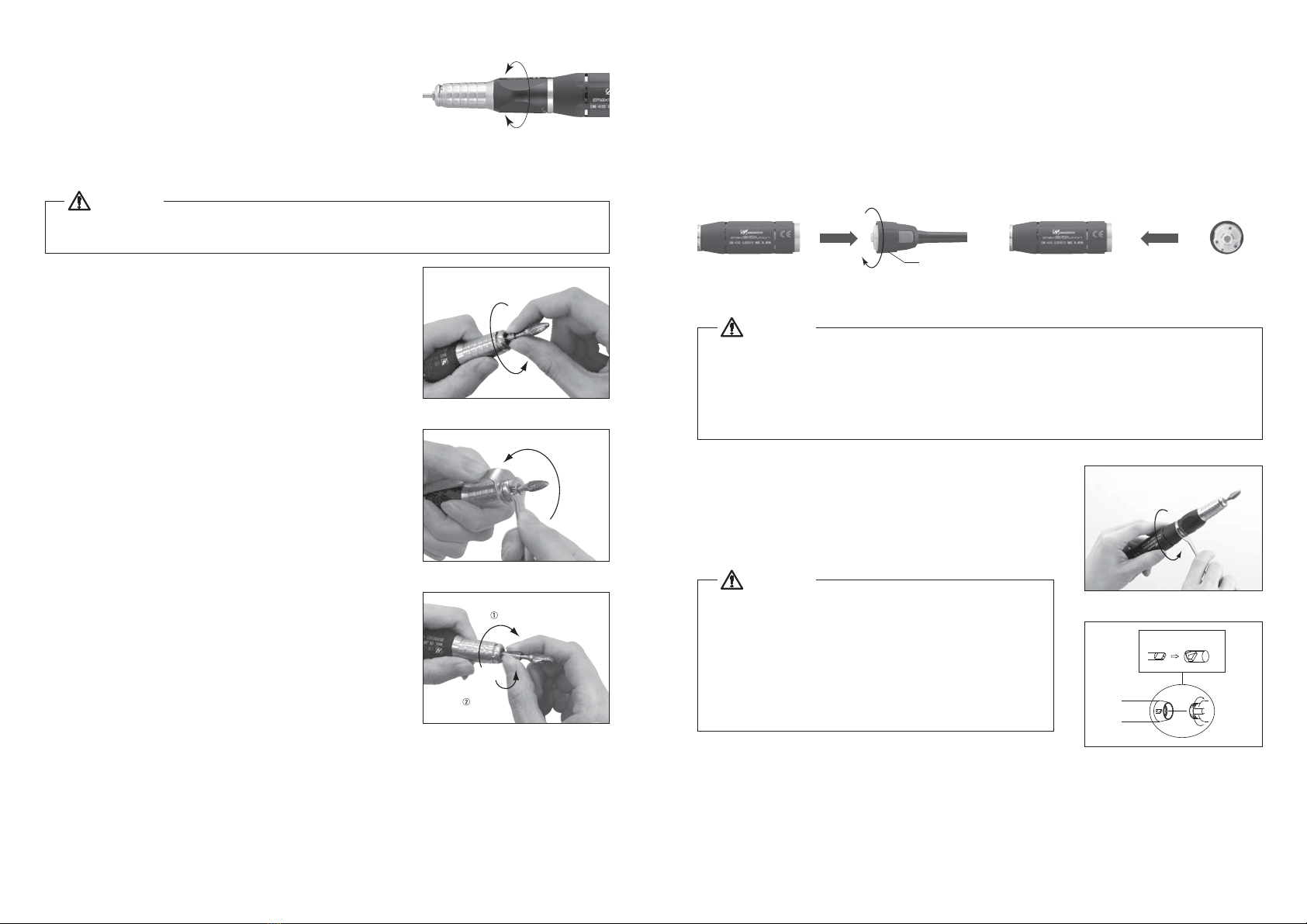
The Attachment does not turn
with the chuck closed
Attachment gets hot during
use
Vibration or Noise during use
High Runout
Bur slips out
Bearings Contaminated or Seized. Send for Service.
Bearings Contaminated. Same as Above.
Same as Above. Same as Above.
Contaminants in chuck or spindle. Clean the chuck and spindle ID.
Chuck is worn. Replace the chuck.
Bearings worn. Send for Service.
Chuck is Loose. Adjust the Chuck.
Bur is bent or damaged. Replace the bur.
Attachment
Trouble Cause/Check Remedy
Speed Display does not light
The power plug is disconnected. Insert the power plug correctly.
Power Switch is faulty.
The connection of the foot control cord plug is loose.
Foot Pedal dose not
work.
Error code E0 appears.
Ask for repair.
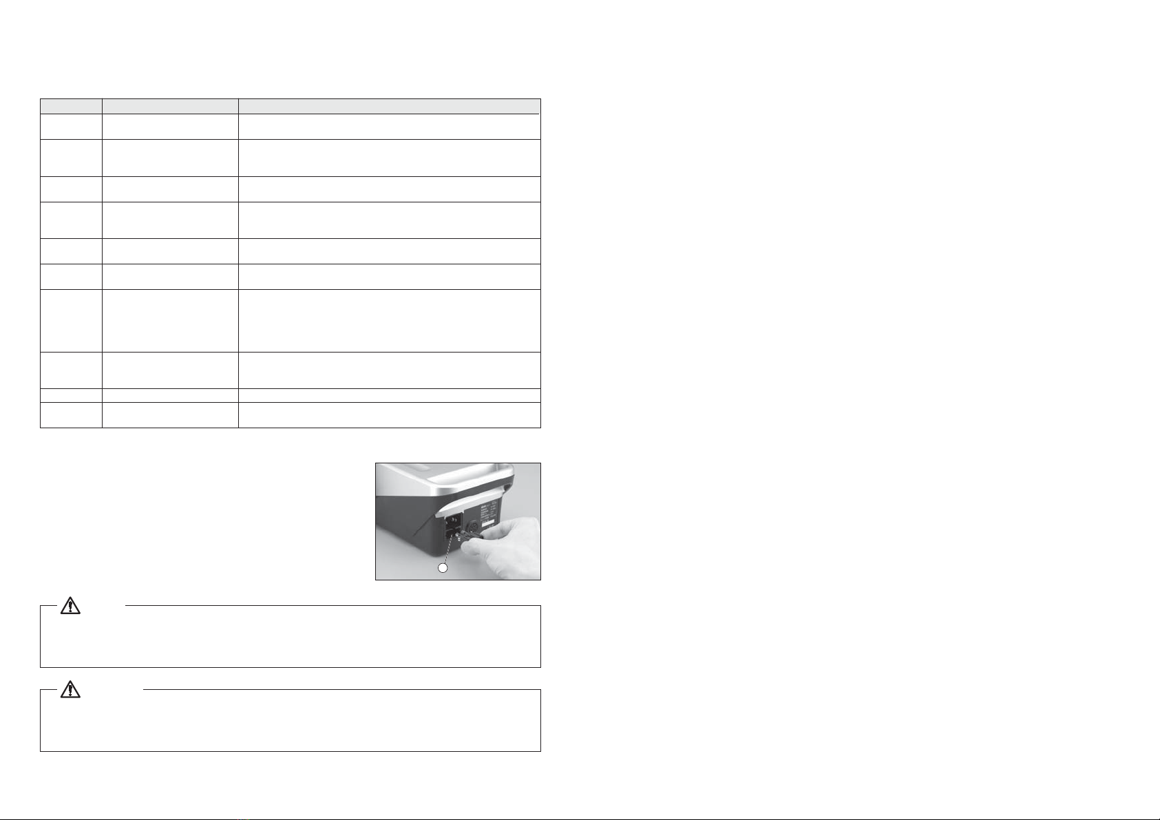
The fuse is blown.
Replace it with a specified fuse. If the reason the fuse has
blown is unknown, ask for an inspection.
The motor and handpiece do not run
Maintenance mode (4) “Pd”: Check to
see if the foot control operates normally.
Connect the foot control cord plug correctly.
If the foot control dose not operates normally, ask for
repair of the foot control or replace it with a new one.
Turn on the power again. If the same error code appears, ask for repair of the unit.
Turn on the power again. If it operates normally, the error display is temporarily due
to overload,which is not a problem.
Error code E1 appears.
If it operates normally after replacing the motor and the motor
cord, the motor and/or the motor cord may be shorted. Ask for
repair of the motor and/or the motor cord. If the same error code
still appears after replacing, ask for repair of the unit.
If you have two or more units, replace
the motor and check the operation.
The motor cord is disconnected. Connect the motor cord correctly.
If you have two or more units, replace the
motor and the motor cord and check the
operation.
Error code E2 appears.
The motor cord is disconnected. Connect the motor cord correctly.
If any problem is found during a check, the motor cord
may be severed or the sensor in the motor may be faulty.
Ask for repair.
If it operates normally, there is no problem. Check the operating
environment, storage location, etc., for high temperature. If the
same error code appears frequently, ask for repair of the unit.
Maintenance mode (3) “HL”: Confirm
whether you work by a motor signal
check normally.
Error code E3 appears.
Error code E4 appears.
After stopping to cool it down place for
about 10 minutes, check the operation
again.
If it operates normally, there is no problem. If the same
error code appears, ask for repair of the unit.
Lock the chuck. If any problem is found during a check, the motor cord
may be severed or the sensor in the motor may be faulty. Ask for repair.
Error code E5 appears.
Error code E6 appears.
Error code E8 appears.
Error code E9 appears.
Error code EF appears.
The rotation speed does not
rise.
Turn on the power again, and repeat
starting and stopping several times.
The chuck is open.
If any problem is found during a check, the motor cord
may be severed or the sensor in the motor may be faulty.
Ask for repair.
Maintenance mode (3) “HL”: Confirm
whether you work by a motor signal
check normally.
If the rotation is abnormal, ask for repair of the motor and
handpiece.
Check turning a tip with a finger lightly
and turning around it lightly.
Error indication is a temporary thing by the overload if I
work normally. There is not it abnormally.
Turn on the power again.
If it operates normally after replacing the motor cord, the motor
and/or the motor cord may be shorted. Ask for repair of the
motor and/or the motor cord. If the same error code still appears
after replacing the motor cord, ask for repair of the unit.
If it operates normally after replacing the motor cord, the motor
and/or the motor cord may be shorted. Ask for repair of the
motor and/or the motor cord. If the same error code still appears
after replacing the motor cord, ask for repair of the unit.
If it does not operate normally, change the Foot Pedal for
new or ask for repair.
Set the maximum rotation speed with the Speed Control
Knob.
If you have two or more units, replace the
motor cord and check the operation.
If you have two or more units, replace the
motor cord and check the operation.
Maintenance Mode (4) “Pd”: Check
whether Foot Pedal operates normally
by Foot Pedal Chuck.
The maximum rotation speed for operation by foot
pedal should be set with the Speed Control Knob.
STroubleshooting
When trouble is found, please check the following prior to consulting your dealer.
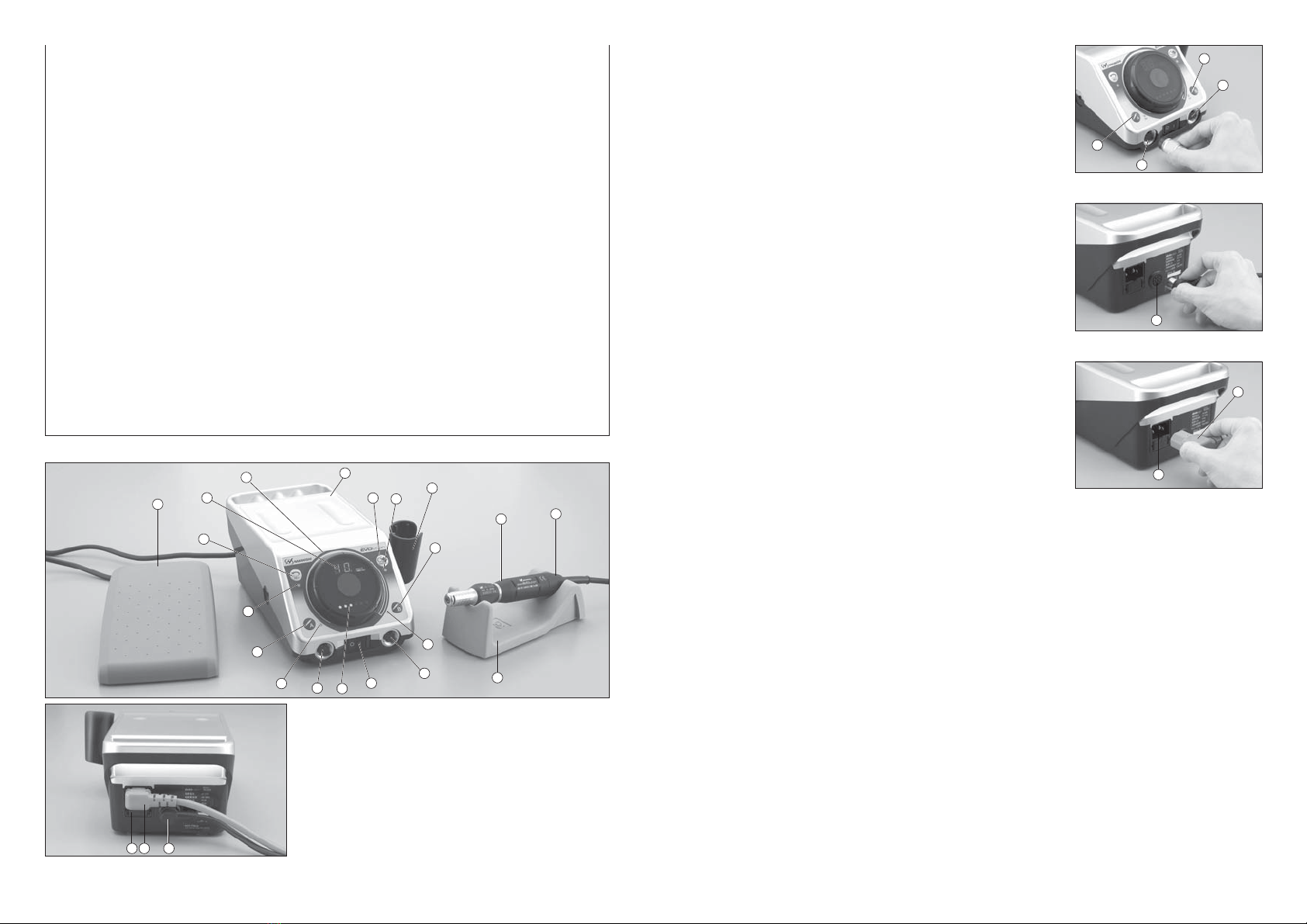
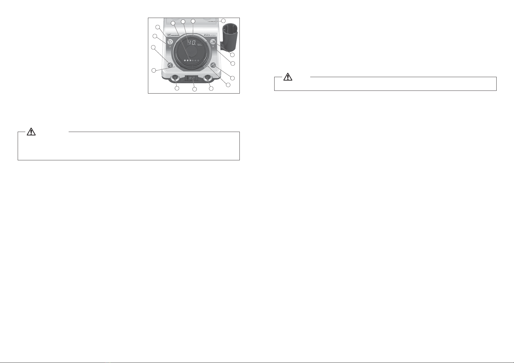
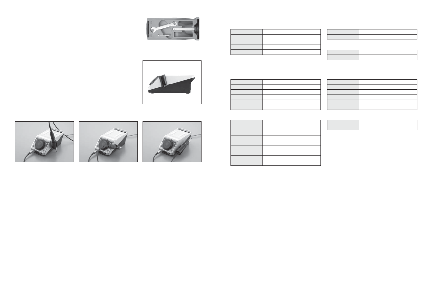
Control Unit and Motor
Product Model No.
Model No. Specification
SOptional Motors and Handpieces
Ring Type Attachment
IR-310
Torque Type Motor
ENK-250T
Standard Type Motor
ENK-410S
Lever Type Attachment
IH-300
Straight Type Attachment
IG-400
Simple lever turning for bur exchange. Designed to make it light
weight and fit to pen-grip type holding. ø2.35mm, ø3.0mm or
ø3.175mm (1/8")
High precision NK Micron Collet Chuck system. Strong tool
retention strength and highly precision metal removal are
achieved.
Torque Type Attachment
HG-200 Chuck Diameter ø6.0mm or ø6.35mm (1/4")
BMH-300
MFC-300S
MFC-300M
90˚Angle Attachment IC-300
90˚Angle attachment with ø3.0mm or ø3.175mm (1/8") Collet Chuck.
When using it with Rubber Pad or Felt buff in lower speed, please use
RG-01 Reducer together.
45˚Angle Attachment KC-300
Reciprocating Type Compact
Grinder LUSTER LS-100
Reciprocating Type Compact Grinder
(Built in motor) LUSTER NLS-110
The grinding surface can be set at any between 0 and 360˚.
Stroke range:0-6mm adjustable by allen wrench.
Fine Belt Sander
KBS-101
8mm Belt (Grits #120, #240, #400 )
6mm Belt (Grits #120, #240, #400 )
4mm Belt (Grits #120, #240, #400 )
1/4 Reduction Gear
RG-01
May be Connected between Motor and Attachment for 4 time
the Regular Power
Extension Joint
CN-01
Joint used by Connection between Attachment and Motor to
Extend the Length
MINI-LUSTER
ML-8
Stroke range of 0.8mm, Reciprocating Stroke (variable):Approx0-9,000 times/min.
Suitable for polishing narrow grooves, details, etc. Stroke range of 0.8mm.
1,000-40,000min-1 Brushless Motor. Excellent combination of high
speed, light weight, small diameter, high torque and FWD/REV
rotation.
1,000-25,000min-1 Brushless Motor. Higher power and higher
torque than Standard motor ENK-410S.
Ring type chucking system makes it easier to change tools.
This unique slim body makes it ideal for cutting and grinding the
bottom surface of deep ribs or holes Chuck diameter ø3.0mm
or ø3.175mm (1/8") Optional ø2.35mm
90˚MINI ANGLE TYPE Attachment for Chamfering Deep Hole,
Bur Only ø1.6mm