BRODBECK IRONWORKS 2X72 GRINDER User manual

1
2X72 GRINDER ASSEMBLY
INSTRUCTIONS
BRODBECK IRONWORKS LLC
REVISION R

2
Contents
Main Chassis Assembly.......................................................................................................... 9
Step 1 –Hinge and Hinge Base RH ......................................................................................9
Step 2 –X Brace............................................................................................................... 10
Step 3 –Hinge Base LH..................................................................................................... 11
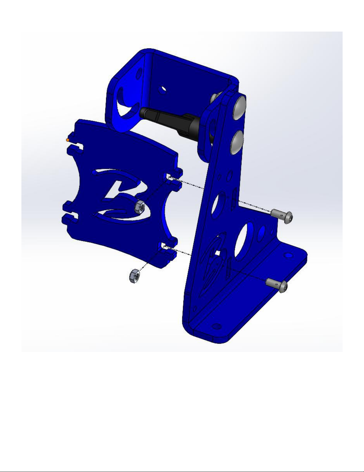
STEP 4 –Hinge Side Plate ................................................................................................. 12
STEP 5 –Tool Arm Plates.................................................................................................. 13
STEP 6 –Motor Mount Side Plate..................................................................................... 14
STEP 7 –Tension Arm ......................................................................................................15
STEP 8 –Gas Spring.......................................................................................................... 16
STEP 9 –Tracking Knob and Handle.................................................................................. 17
STEP 10 –Tracking Wheel ................................................................................................ 17
STEP 11 - Motor Install..................................................................................................... 18
STEP 12 - Drive Wheel Install............................................................................................ 19
Wiring Instructions ..............................................................................................................21
Variable Speed Motor Wiring........................................................................................... 21
VFD Setup ....................................................................................................................... 23

3
WARNING:
THE OPERATION OF THIS MACHINE MAY RESULT IN INJURY, DISMEMBERMENT, OR DEATH.
Lockout and secure power source before performing any work on the machine.
Make sure to use adequate personal protection equipmentsuch as eye protection,
respirator, etc. while operating this equipment.
Contact Brodbeck Ironworks LLC for any questions or concerns before operating this
equipment
Ben Secrist 513-532-7062, Ben@brodbeckironworks.com

4
Parts List:
ITEM
DESCRIPTION
QTY
IMAGE
1
HINGE BASE RH 2X72
1
2
HINGE BASE LH 2X72
1
3
FORMED HINGE 2X72
1
4
½” CARRIAGE BOLT 1-
1/4”LG
4
5
½” THIN NYLOCK NUT
9
6
½” TEFLON WASHER
.020” THK
3

5
7
BLACK ADJUSTABLE
HANDLE ½”-13
INTERNAL THREAD
2
8
5/16” X 3/4”LG SCREW
4
9
5/16” THIN LOCK NUT
10
10
½” FLAT SAE WASHER
9
11
1/4” FLAT WASHER
4
12
GRAY ADJUSTABLE
HANDLE 3/8”-16
EXTERNAL THREAD
2
13
3/8" HEX BOLT 5/8” LG
2
14
HINGE-SIDE SIDE PLATE
1

6
15
TOOL ARM TOP PLATE
2
16
TOOL ARM PLATE
2
17
5/16” CARRIAGE BOLT
2-1/2” LG
4
18
MOTOR MOUNT SIDE
PLATE
1
19
5/16” SPACER 1/2" ID
1.0”OD
3
20
½” CARRIAGE BOLT 1-
3/4”LG
1
21
TRACKING/TENSIONING
ASSEMBLY
1

7
22
GAS SPRING (20LB)
1
23
GAS SPRING EYELET
2
24
5/16” HEX BOLT 1”
LONG
2
25
3/8” THREADED
TAPERED HANDLE
1
26
LOBED TRACKING KNOB
3/8” THREADED
1
27
4” TRACKING WHEEL
1
28
MOTOR
1
29
3/8” HEX BOLT 1”
LONG
4
30
3/8” SPLIT LOCK
WASHER
4

9
Main Chassis Assembly
Step 1 –Hinge and Hinge Base RH
Insert a 1/2" x 1-1/4" long carriage bolt into the top hole of the Hinge Base. Then add a 1/2"
teflon washer (.020" thick) to the bolt. Add the hinge on top of the carriage bolt. Then add a
1/2" metal flat washer and a 1/2" nut. Tighten until you can barely rotate the hinge.
Insert a 1/2" x 1-1/4" long carriage bolt into the bottom hole of the Hinge Base through the
slot of the Hinge. Add a 1/2" metal flat washer and screw on the Large Black Handle (Item 6).
The handle can be adjusted by pulling up on the handle and rotating. You may need to hold
the threaded portion while rotating the handle.

10
Step 2 –X Brace
Insert X-Brace into the Hinge Base. Slide 5/16-18 nylock nuts into the X-Brace. Secure with
5/16-18 x 3/4” long Button Head Screw by inserting it through the Hinge Base into the nylock
nut.

11
Step 3 –Hinge Base LH
Insert a 1/2" x 1-1/4" long carriage bolt into the top and bottom hole of the Hinge Base. Then
add a 1/2" teflon washer (.020" thick) to the top bolt. Install the Hing Base onto the X-Brace
and Hinge. Then add a 1/2" metal flat washer and a 1/2" thin nylock nut. Tighten until you can
barely rotate the hinge.

12
STEP 4 –Hinge Side Plate
Install the 3/8-16 Threaded Handles into the Hinge-Side Side Plate. Do not tighten down all the
way. Only tighten until the tip of the threads meet the inside face.
Lower the hinge-side side plate onto the hinges. Use two 3/8-16 x 5/8” Long hex head bolts.

13
STEP 5 –Tool Arm Plates
Install the tabs of (in order from front to back) the tool arm top plate and tool arm plates (3),
into the slots of the hinge-side side plate.

14
STEP 6 –Motor Mount Side Plate
Place the motor mount side plate onto the tool arm and tool arm top plates.
Insert (4) 5/16-18 x 2-1/2” carriage bolts and secure with the 5/16 nylock nuts. If you
overtighten the sides plates may bow outward.

15
STEP 7 –Tension Arm
Install the tension arm using the ½-13 x 1.75” carriage bolt, spacer, flat washer(s), and nylock
nut. Tighten enough to eliminate side to side wobble. Overtightening can cause tracking
issues. Additional washers are provided to fine tune the tracking.

16
STEP 8 –Gas Spring
Install the gas spring using 5/16-18 x 1.00” hex bolt, a flat washer on both sides of each eye,
and nylock nut.
Do not overtighten the gas spring bolts. It will bind and cause tracking issues and premature
failure.

17
STEP 9 –Tracking Knob and Handle
Insert 3/8-16 threaded handle into the tension arm (apply loctite). Install 3/8-16 threaded
knob into the tension arm. This will be used to adjust tracking in operation.
STEP 10 –Tracking Wheel
Install the tracking wheel into the tracking arm using ½-13 x 3” hex bolt, nylock nut, and flat
washer.
BE CAREFUL NOT TO OVERTIGHTEN BEARINGS. THE WHEEL SHOULD SPIN FREELY BUT THERE
SHALL NOT BE EXTRA SPACE BETWEEN THE BEARINGS AND NUT OR BOLT HEAD.

18
STEP 11 - Motor Install
Tilt the chassis into the horizontal position. Install motor into belt side plate using 3/8-16 x 1
hex bolts and split lock washers. Make sure the feet of the motor are facing the rear of the
machine.

19
STEP 12 - Drive Wheel Install
Install drive wheel and secure with set screw.
Align with other wheels to ensure proper tracking. The drive wheel should be approximately
7/16” off of the side plate.

20
Additional Notes:
-Make sure all wheel centerlines are aligned with each other to ensure proper tracking.
There may be some variance due to tolerance stack ups.
-To make sure the belt has enough tension, put the belt on all four wheels, pull and hold
down the tension arm all the way, pull the platen arm out until the belt is tight, lock the
platen arm in place, and release the tension arm.
-When adjusting tracking, start off rotating by hand or running the motor at a slow
speed.
-Always adjust the speed on your VFD to 0 when starting after an attachment change
-The VFD Start/Stop switch is a three-way switch.
oSTOP (Bottom position)
oRUN (Middle position)
oSTART (Top Position, will spring back to middle)
PLACE ALL WARNING LABELS ONTO THE MACHINE IN A VISIBLE
LOCATION.
Other manuals for 2X72 GRINDER
1
Table of contents
Other BRODBECK IRONWORKS Grinder manuals