Link L1500 Series User manual

Link L1500 Series Systems Manual
1Products Covered. 2
2System Description 3
3L1500 Series Encoder/Transmitter 4
3.1 Operation 4
3.2 L1500 Connector Interface 10
3.3 L1500 HD Transmitter Description and Specification 11
3.4 Input / Output Connections 12
3.5 Mechanical 14
4L1520 Camera Controller / Data Receiver – Optional 14
5L2132/4 SD/HD Receiver 15
5.1 Controls 15
5.2 Operator Menus 15
5.3 Receiver Setup 19
5.4 Connectors 20
5.5 L2132/4 HD/SD Demodulator/Decoder Description and Specification 21
5.6 Input / Output Connections 21
6L3070/50 DownConverter (Base) 23
6.1 DownConverter Description and Specification 24
6.2 Mechanical 24
7L1255 Wireless Camera Control Unit (CCU) Interface 25
7.1 Controls and Setup 25
7.2 Connectors 25
7.3 Unit Description 26
8Maintenance & Firmware Upgrades 28
8.1 L1500 RF / Up Converter and Camera Control Module Removal 28
8.2 L1500 Firmware Upgrades 28
8.3 Link ½ 19” Rack Based Products 29
8.4 L30*0 Down Converter Filter Change 29
9Part Numbers for Link Research Accessories 31
Images are for illustration only and may differ from components supplied
Link Research Ltd www.linkres.co.uk Support UK/Europe + (44) 1923 474099 USA +(1)9786715700
Page 1 of 31 CL140045 Issue C Link L1500 Series System Manual

Document Link L1500 HD Series Systems Manual
1Products Covered.
Link Part Number Product Description Details
L1500 L1500 Transmitter – Base Unit
L1510-1927 L1500 RF Module / UpConverter 1.95 – 2.7 GHz
L1510-3236 L1500 RF Module / UpConverter 3.2 – 3.6 GHz
L1510-5859 L1500 RF Module / UpConverter 5.8-5.9 GHz
L1510-6471 L1500 RF Module / UpConverter 6.4 – 7.1GHz
L1510-6875 L1500 RF Module / UpConverter 6.8 – 7.5GHz
L3020/70 Downconverter Base Unit 2/7GHz
L3014 Downconverter Filter 1.435- 1.525GHz Use with L3070 base (Hi 1.84GHz)
L3030 Downconverter Filter 1.95-2.7GHz Use with L3070 base (Lo 1.84GHz)
L3033 Downconverter Filter 2.2-2.3GHz Use with L3070 base (Lo 1.83GHz)
L3034 Downconverter Filter 2.3-2.4GHz Use with L3070 base (Lo 1.84GHz)
L3037 Downconverter Filter 2.5-2.7GHz Use with L3070 base (Lo 1.84GHz)
L3080 Downconverter Filter 6.425-7.125GHz Use with L3070 base (Lo 7.64GHz)
L3050 Downconverter Base Unit 3GHz
L3060 Downconverter Filter 3.4-3.58GHz Use with L3050 base (Lo 3.068GHz)
L2132/4 HD/SD IRD Receiver 2Ch/4Ch UHF input 70-880MHz
L2140 HD/SD Decoder ASI in only
L1255 Wireless CCU Interface
L1520 Link L1500 Camera Control Module
Issue Date Comments
A July 07 Working draft – based on LinkHD
(L1400) Manual
B Oct 07 Initial release
C Oct 07 Minor edits
Safety and Compliance
Any mains power equipment must be earthed. Operate the equipment within environmental limits and
ensure as much ventilation as possible (Normally Temp 0C-50C <99% humidity). Only authorised
personnel should open the product and any repair or warranty will be invalidated if the seals are
broken. The equipment has been designed to be CE compliant and an EC Declaration of Conformity
and Technical files are available on request.
Please contact Link SUPPORT any issues.
Please ensure that normal anti-static precautions are taken when removing the L1500 modules from
the main unit.
Images are for illustration only and may differ from components supplied
Link Research Ltd www.linkres.co.uk Support UK/Europe + (44) 1923 474099 USA +(1)9786715700
Page 2 of 31 CL140045 Issue C Link L1500 Series System Manual

Images are for illustration only and may differ from components supplied
Link Research Ltd www.linkres.co.uk Support UK/Europe + (44) 1923 474099 USA +(1)9786715700
Page 3 of 31 CL140045 Issue C Link L1500 Series System Manual
2System Description
The Link L1500 HD wireless radio camera system comprises of three main components :-
Link HD Transmitter - L1500+L1510* Upconvertor
Link RF Down Converter (2 off) - L3070 (2/7GHz) or L3050 (3GHz)
Link HD Receiver - L2132/4
*Note- In this manual L1510 is used to denote any of the optional RF / UpConverter modules.
Optional components for camera control :-
Link Wireless CCU Interface - L1255
Link HD Camera Controller - L1520
For Camera manufacturers OCP, Grass Valley OCP400; Sony 700 Series, and Link Generic (Ikegami
HDK future)
The basic system will include 3dBi Omni vertically polarized antenna for the transmitter and down
converters; a range of alternative antennas can be supplied to meet different operational
requirements.
These will provide the basic operation of the Link HD system although other configurations are
possible including diversity operation, through Triax and fibre etc.
Please contact Link Research Ltd for details.
For basic operation, connections to the L1500 HD Transmitter unit are HD/SD video, analogue audio
and if required an RS232 data link. Power is supplied either via the attached battery plate or external
LEMO connector.
The power switch on the side of the L1500 is provided to switch the L1500 / L1520. This switch
cannot be used to control the supply to the forward camera interface plate which is always fed power
from the battery or external Lemo connector.
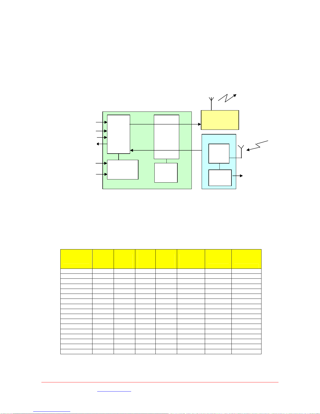
Max 4, Min 2
L30**
Downconverters
L2132/4 HD/SD
IRD Receiver
L1500 Encoder
Transmitter
HD/SD-Video
In
HD/SD-SDI
Out
TALLY A
Remote / Data
Receiver Interface
Antenna
TALLY B
OCP - Sony
OCP - RS232
ASI
In
CH
1
CH
2
ASI
Out
SDI
Out#1
SDI
Out#2
F/Loc
k
Camera
Control
Remote /
Data
RF 2RF 1 RF 3 RF 4
L1255
interfacing into
OCP (option)
Images are for illustration only and may differ from components supplied
Link Research Ltd www.linkres.co.uk Support UK/Europe + (44) 1923 474099 USA +(1)9786715700
Page 4 of 31 CL140045 Issue C Link L1500 Series System Manual
The L1500 can be supplied with various interface plates providing mounting of different batteries and
to different camera mounts - either IDX / Sony ‘V’ , PAG Loc or Anton Bauer Gold Mount are available.
Adaptor brackets are also available to allow mounting of the L1500 to the rear of Thompson LDK6000
series of cameras and the Sony 1500 series. These interface plates provide a ‘quick release’ to
remove the transmitter from the camera
A full list of accessories and cables is given at the end of this document
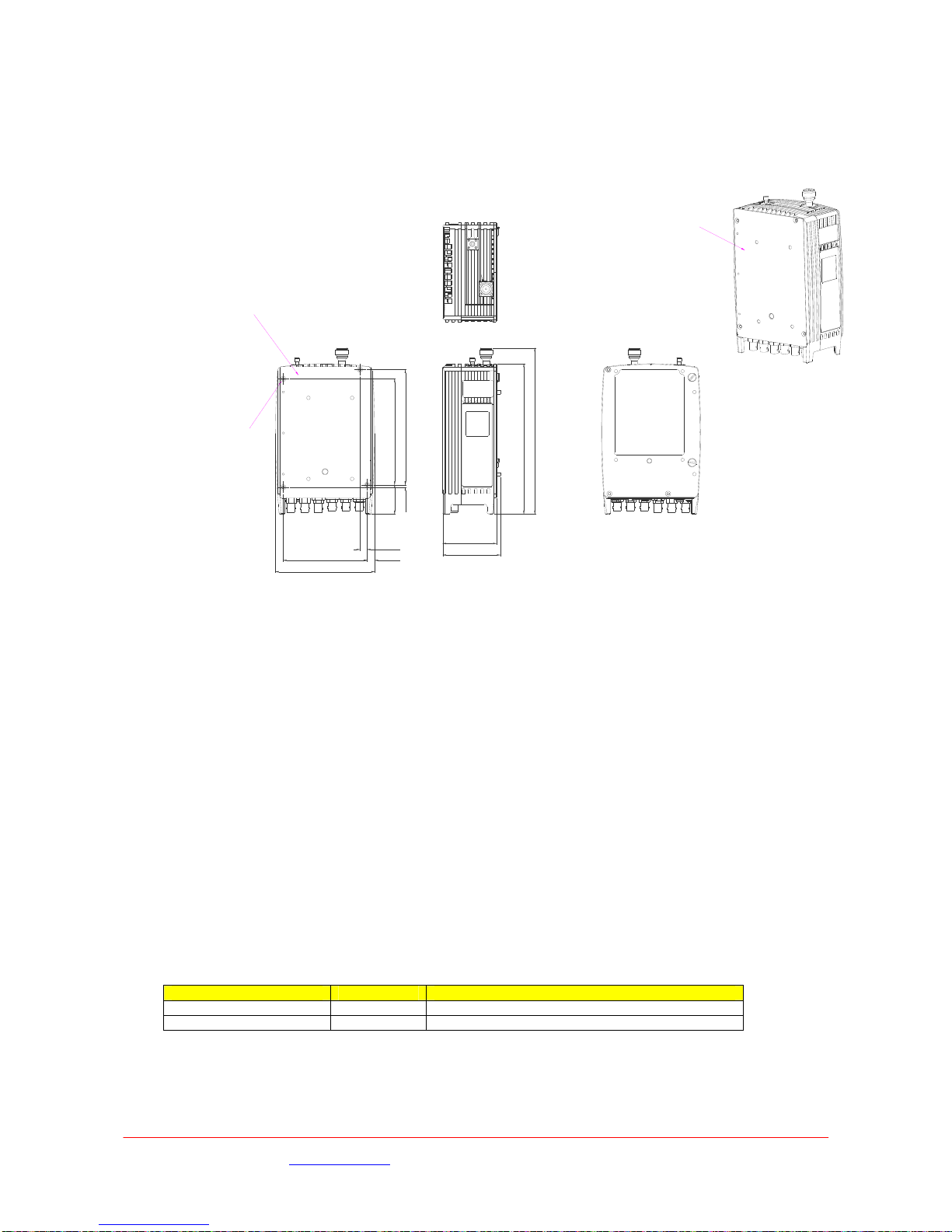
3L1500 Series Encoder/Transmitter
The L1500 Series Encoder/Transmitter is a compact HD/SD MPEG2 Encoder, DVB-T and LMS-T
modulator and 100mW output power amplifier (250mW FCC only). LMS-T is a unique robust
modulation scheme developed specifically for wireless camera use.
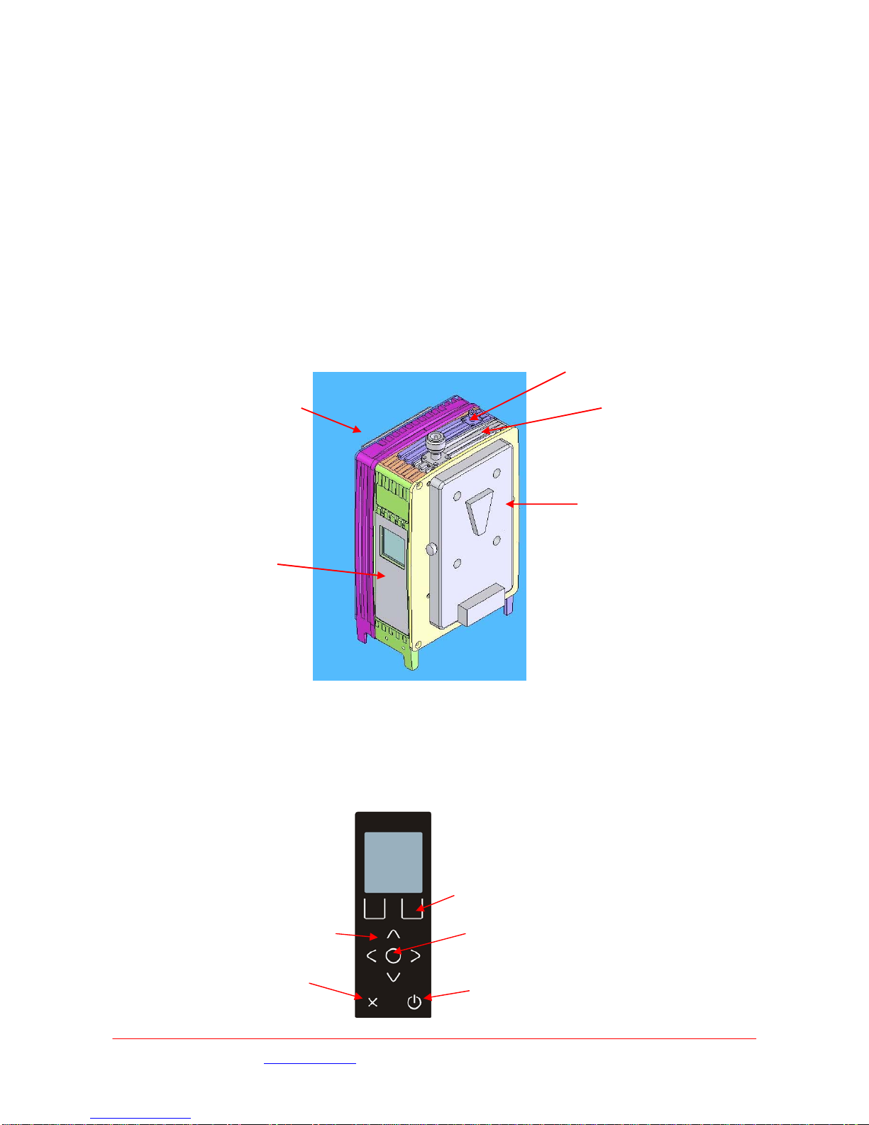
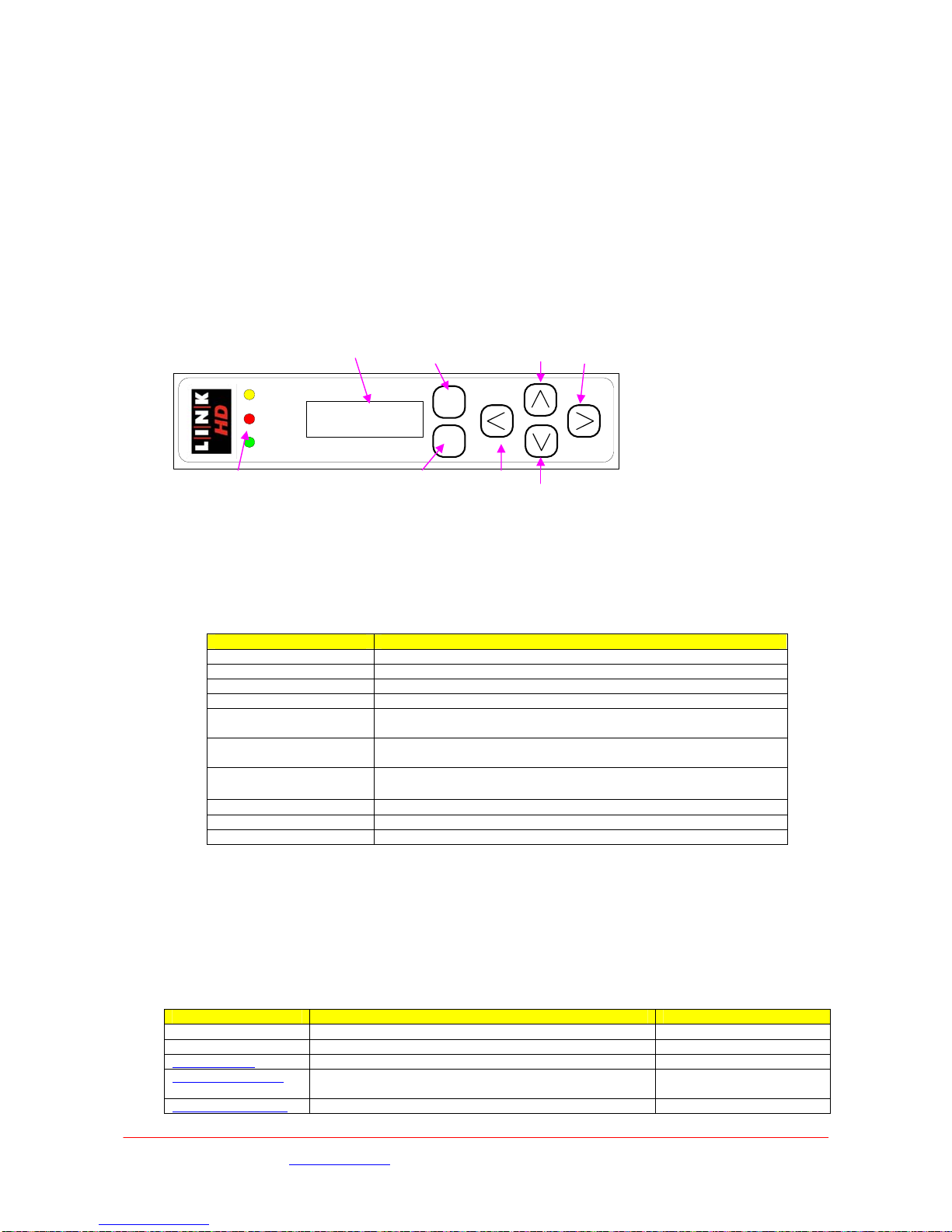
3.1 Operation
The L1500 is configured by the operator using the menu structure displayed on the colour LCD
display, 9 membrane push buttons are used to navigate through these menus and select the required
data. Please see 3.1.2 below for details of the L1500 menu structure.
Control
Camera Control Module
– L1520
RF Module /Up Converter
Module – L1510
Camera Interface
Battery
Interface
Panel
Function ke
y
s
–
action de
p
ends u
p
on
p
osition within menu
‘Enter’
‘Power’
U
p
/ Down / Left /Ri
g
ht
‘Cancel’ / ‘Exit’
Images are for illustration only and may differ from components supplied
Link Research Ltd www.linkres.co.uk Support UK/Europe + (44) 1923 474099 USA +(1)9786715700
Page 5 of 31 CL140045 Issue C Link L1500 Series System Manual
The left / right and up / down buttons are used to select the required menu, or sub-menu the
Enter selects highlighted option which can then be modified with the up / down buttons.
Enter will then select the option or Cancel (‘X’) will exit back to the level above without selecting or
changing the settings..
Two Function keys are also available and can provide ‘short cuts’ into various functions without
navigating through the menu structure.
The ‘Status’ display can be used to display the battery voltage and current consumption of the
L1500 unit.
A single ’soft’ Power switch is also provided to control the L1500 unit. This switch must be pressed
for ~3secs to switch the L1500 on or off. This is to avoid accidental switching of the unit due to
knocking the power switch.
When power is applied to the L1500 it will revert to the condition when the power was removed.
E.g. If the L1500 was off when the power was removed; the power switch will need to be pressed to
turn the unit on. If the L1500 was on when the power was removed the unit will automatically power
on.
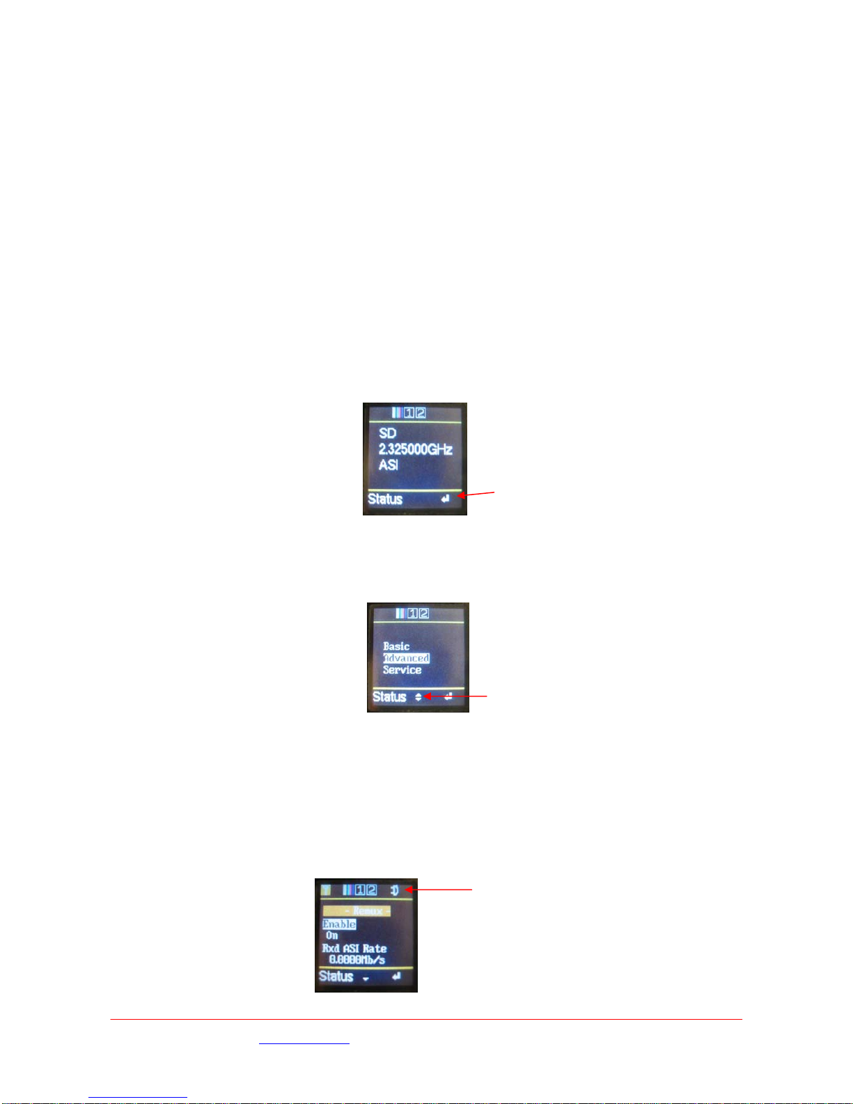
3.1.1 L1500 Display
Status Display
The ‘normal’ status display gives confirmation of the main operating configuration of the L1500 unit.
The transmit frequency, RF , modulation mode or ASI operation.
Pressing the Enter button will enter the top level menu where either of the three sub menus can be
selected.
Example of a sub menu showing the use of highlighted options to show the currently selected item.
The arrows on the lower line of the display indication whether further items are available by scrolling
up or down from the current position.
Icons are used to display the status of video input, bars, audio and remux on the top line of the status
display.
Icons showing :-
RF On, Bars On, Audio1 On, Audio2 On, Remux On
Arrow indicating further options available by scrolling
up / down through the menu
‘Function’ key definition
3.1.2 L1500 Menus
The Greyed Out parameters not selectable with the current version of code.
The table below is splli into the three ‘Levels’ corresponding to BASIC, ADVANCED and SERVICE levels
of operation.
The BASIC functions are also included in the ADVANCED level, this is to allow all functions of the unit
to be configured by a competent operator; the normal operational functions can then be changed at
the BASIC level.
The SERVICE functions are intended for diagnostics and servicing by a technician / engineer.
BASIC FUNCTIONS
Options Function Comment
Modulator Frequency Range dependent on module
fitted
Only if module detected and NOT in
ASI mode
RF Output Level 10,50,100,250mW
RF Output On/Off
Mod. Mode QPSK,16QAM,64QAM
Video Source Video Input 1080i/50,720p30 etc etc Options dependent on either SD or
HD
Test Pattern On/Off
Video Loss Bars, Blank, Bars+Audio If no video input detected sets Bars
On
Audio Ch1 Enabled On/Off
Input Analogue, Test Tone,
Embedded, Channel ID’s
Mic/Line Mic or Line level input Mic adds +25dB gain & optional
Phantom Power
Phantom Power On / Off Only if Mic is selected
Level Left Sets required gain
Level Right
Audio Ch2 As Ch1
Status Temperature Display units internal temp
Service Name Display / set units current
Service Name
Serial Number Display units serial number Should be quoted in all enquiries
with service department
Licence Code Display units licence code Defines units enabled features
Camera
Control
Camera Type Selects camera type in use
Frequency Sets UHF receiver frequency
ADVANCED FUNCTIONS
Options Function Comment
System Auto Set Service 1… Sets PID information for multiple
camera operation
Restore default Yes / No Sets unit configuration to Default
values
Save Profile 1… Stores current configuration
Load Profile Yes / No Loads saved configuration
Last Profile 1…
Lock Panel Locked / Unlocked
Unit Fans Off/Auto Control units fans
Download Allows download new unit firmware
Modulation Frequency Range dependent on
module fitted
Only if module detected
RF Output Level 10,50,100,250mW
RF Output On/Off
Mod. Mode QPSK,16QAM, 64QAM LMS-T QPSK & 16QAM only
Mod. Type LMS-T, DVB-T
Guard Interval 1/32 ….
FEC ½ ……
Bandwidth 6,7,8,10 & 20MHz …. LMS-T 10 & 20MHz; DVB-T 6,7,8MHz
Mod. Polarity Normal, Invert
Multiplexer ASI Packet Off,188,204 bytes
ASI Bit Rate 10.000Mb/s Display / set output bit rate
Service Name
Network Name
PMT PID Sets PID 0 - 9999
Images are for illustration only and may differ from components supplied
Link Research Ltd www.linkres.co.uk Support UK/Europe + (44) 1923 474099 USA +(1)9786715700
Page 6 of 31 CL140045 Issue C Link L1500 Series System Manual

PCR PID Sets PID 0 - 9999
Local Service On, Off
Program ID Sets ID 0 - 9999
Network ID Sets ID 0 - 9999
TS ID Sets ID 0 - 9999
Video Encoder Video Input 1080i/50,720p30 etc etc Options dependent on either SD or
HD
Test Pattern On/Off
Video Loss Bars If no video input detected sets Bars
On
SD / HD HD / SD Selects either SD or HD video input
formats
Encoder On / Off Turns of local encoder
Auto Bit Rate On / Off Encoder set to maximum rate for TS
or modulation setting
Enc Bit Rate 12.456Mb/s Shows current bit rate. If NOT auto
bit rate sets encoder bit rate setting.
MPEG 4:2:0 / 4:2:2
GOP Length 8…. Sets required GOP Length
Video PID 0-9999 Sets required Video PID
Enc type Std / Low Delay Only if SD encoder
Audio Ch1 Enabled On/Off
Input Test Tone, Analogue,
Embedded
Mic/Line Mic or Line level input Mic adds +25dB gain & optional
Phantom Power
Level Left Sets required gain
Level Right
Type MPEG L1,L2, Linear
Bit Rate 320Kbs
Mode Dual Mono, Stereo
Language Eng, Fre,Ger,Spa
Tone Level -18dBFS Sets output level of Test Tone
PID 0-9999
DID 0-9999
Audio Ch2 As Ch1
Remux Enable On, Off Turns the remux (external ASI input)
on / off
Input Rate 12.456Mb/s
Status Not Active Shows condition of remux input
RS232 Data Data On, Off, Low delay, TTV
Baud Rate 9600
Data PID 0-9999
SERVICE FUNCTIONS
Options Function Comment
Encoder Serial Number Display units serial
number
Should be quoted in all enquiries with
service department
Licence Code Allows Licence code
changes
Defines units enabled features
Software Revision 1a2 Displays Encoder firmware revision
Module1 Status Fitted
Type 2.5GHz
Temperature Module temperature
Software Revision 1a2 Displays module firmware revision
Module2 Status Not Fitted
Versions Code Version 1c3 Main unit firmware revision
Shows versions of all programmable
devices in the L1500
Cust. Support Contact Details
Debug Debug Cmd Used for detailed diagnostics
Debug Parameter Used for detailed diagnostics
Images are for illustration only and may differ from components supplied
Link Research Ltd www.linkres.co.uk Support UK/Europe + (44) 1923 474099 USA +(1)9786715700
Page 7 of 31 CL140045 Issue C Link L1500 Series System Manual

3.1.3 Transmitter Setup
It is important that when changing between modes of operation it is necessary to check and re-select
certain operating parameters due to interaction of some of these parameters.
For example when changing from DVB-T to LMS-T mode it will be necessary to reset the required
modulation scheme.
In the following examples the menus are described by :-- Level / Sub Menu / Function.
Some of the settings can be made from either the BASIC or the ADVANCED menus; the more
‘complex’ are only available from the BASIC level.
Following a ‘Restore Factory Defaults’ (Advance/System/Restore Defaults) it will be necessary to
select the required operating mode and modulation configuration as the factory defaults will not
currently give an operational setup and may result in ‘garbage’ characters on the display.
3.1.3.1 DVB-T Operation
The following sequence defines the changes and sequence required when changing to DVB-T
operation :-
Step Menu Sub Menu Option Setting
1 Advanced Modulation Modulation Type DVB-T
2 Advanced Modulation Guard Interval Must match
receiver
3 Advanced,Basic Modulation Modulation Mode As Required
4 Advanced Modulation FEC Rate As Required
5 Advanced Modulation Polarity Must Match
Receiver
6 Advanced Modulation BandWidth Fixed at 8MHz
7 Advanced,Basic Modulation Power As Required
8 Advanced,Basic Modulation Frequency As Required
9 Advanced,Basic Modulation RF Output On
The MPEG2 encoder will set the data rate appropriately to match the modulation scheme settings.
The Table below defines the corresponding bit rates for DVB-T operation.
Modulation GI
CR
1/4 1/8 1/16 1/32
QPSK 1/2 4.97 5.52 5.85 6.03
QPSK 2/3 6.63 7.37 7.80 8.04
QPSK 3/4 7.46 8.29 8.78 9.04
QPSK 5/6 8.29 9.21 9.75 10.05
QPSK 7/8 8.70 9.67 10.24 10.55
16QAM 1/2 9.95 11.05 11.70 12.06
16QAM 2/3 13.27 14.74 15.61 16.08
16QAM 3/4 14.92 16.58 17.56 18.09
16QAM 5/6 16.58 18.43 19.51 20.10
16QAM 7/8 17.41 19.35 20.49 21.11
64QAM 1/2 14.92 16.58 17.56 18.09
64QAM 2/3 19.90 22.11 23.41 24.12
64QAM 3/4 22.39 24.88 26.34 27.14
64QAM 5/6 24.88 27.64 29.27 30.16
64QAM 7/8 26.12 29.02 30.73 31.66
The selections greyed out are available in the transmitter , but not in the current version of the
receiver firmware. Check Support for updates.
These rates can be confirmed by checking the Advanced/Multiplexer/ Bit Rate menu.
It should be noted that this corresponds to the total data rate from the multiplexer which includes the
video, audio and any user data.
Images are for illustration only and may differ from components supplied
Link Research Ltd www.linkres.co.uk Support UK/Europe + (44) 1923 474099 USA +(1)9786715700
Page 8 of 31 CL140045 Issue C Link L1500 Series System Manual

3.1.3.2 LMS-T Operation
The following sequence defines the changes and sequence required when changing to LMS-T
operation :-
Step Menu Sub Menu Option Setting
1 Advanced Modulation Modulation
Type
LMS-T
2 Advanced Modulation Guard Interval As Required. 1/8
or 1/16. Must
match receiver
3 Advanced,Basic Modulation Modulation As Required 16Q
or QPSK
4 Advanced Modulation FEC Rate 2/3 Only
5 Advanced Modulation Polarity Normal
6 Advanced Modulation Width 10MHz or 20MHz
7 Advanced,Basic Modulation Power As Required
8 Advanced,Basic Modulation Frequency As Required
9 Advanced,Basic Modulation RF Output On
The encoder will set the data rate appropriately to match the modulation scheme settings.
The Table below defines the corresponding bit rates for LMS-T operation for both 10MHz and 20MHz
operation.
Modulation GI
CR
1/8
10MHz 20MHz
1/16
10MHz 20MHz
QPSK 2/3 9.2 18.4 9.7 19.5
16QAM 2/3 18.4 36.8 19.5 39
64QAM 2/3 27.6 45.2 29.2 58.5
Note 64 QAM not available on current software.
These rates can be confirmed by checking the Advanced/Multiplexer/Bit Rate menu.
It should be noted that this corresponds to the total data rate which includes the video, audio and any
user data.
Due to the improvement that LMS-T has over DVB-T these settings give approximately 50%
improvement of bit rates for the same level of ruggedness of the RF link.
For example DVB-T 16QAM, 1/32 GI, 1/2 CR gives 12Mbits whereas LMS-T 16QAM gives 18Mbits
3.1.3.3 ASI Operation
The L1500 can be used as an MPEG2 HD encoder providing an ASI output. The modulator and RF Up
converter are not required in this operating mode.
This provides ASI streams up to 90Mbits.
Step Menu Sub Menu Option Setting
1 Advanced Modulation Modulation Type ASI
2 Advanced Multiplexer ASI Bit Rate As Required
3 Advanced Video Encoder Bit Rate As Required
The encoder bit rate cannot be set above the Mux bit rate, if an attempt is made to exceed the mux
setting the encoder value will clamp to the highest allowed rate.
3.1.3.4 Remux Operation
The L1500 can be used to re-multiplex an additional service into the ASI data stream. This allows
two services can be transmitted on one RF Channel.
Step Menu Sub Menu Option Setting
1 Advanced Remux Enable On
It is important that the remultiplexed service multiplexer rate and the internal generated service
multiplexer data rate are within the available RF modulated data rate.
Images are for illustration only and may differ from components supplied
Link Research Ltd www.linkres.co.uk Support UK/Europe + (44) 1923 474099 USA +(1)9786715700
Page 9 of 31 CL140045 Issue C Link L1500 Series System Manual

3.1.4 Video Input Format
It is important that the encoder is configured to match the incoming video format. The rates MUST
match otherwise the encoder may appear to operate correctly but then fail with changing video
images.
Menu Sub Menu Option Setting
Advanced Video HD Input Unit As required
3.1.5 Audio Input Format
Step Menu Sub Menu Option Setting
1 Advanced Audio A or B Type Encoding as required
2 Advanced,Basic Audio A or B Input As Required
3 Advanced Audio A or B Bit Rate As Required
4 Advanced Audio A or B Mode As Required
5 Advanced,Basic Audio A or B Line / Mic As required
6 Advanced,Basic Audio A or B Phantom Pwr If Mic selected
7 Advanced,Basic Audio A or B Mic or Line
Level
Set required gain
3.2 L1500 Connector Interface
Top Panel Connector RF out N Type Male 50 ohm connector.
Side Panel Connectors USB, serial interface used for firmware upgrades etc
Lower Panel Connectors Position of panel connectors on the L1500 transmitter.
Connector type Legend Description
BNC 75Ωbayonet socket SDI In SD/ HD-SDI (SMPTE 259M / SMPTE 292M)
BNC 75Ωbayonet socket ASI OUT DVB-ASI – output from the MPEG2 encoder
BNC 75Ωbayonet socket ASI IN DVB-ASI – into the Remux for modulation
BNC 75Ωbayonet socket Y/CV PAL or NTSC (625 / 525) SD only, also Y for
component
BNC 75Ωbayonet socket Pr Component SD only
BNC 75Ωbayonet socket Pb Component SD only
XLR3 Female A1L / A1R Ch1 Analogue audio inputs. Line or Mic level
6 way LEMO A2 Ch2 Analogue audio inputs. Line or Mic level
6 way LEMO DATA RS232 connection for Link Control
4 way LEMO PWR External 12V battery supply if rear ‘clip on’ battery
is not used.
It is also possible to take power from the ‘clip on’
battery.
Care must be taken to ensure that the ‘clip on’
battery on the rear of the L1500 is not ‘back fed’
by an external battery or power supply.
Images are for illustration only and may differ from components supplied
Link Research Ltd www.linkres.co.uk Support UK/Europe + (44) 1923 474099 USA +(1)9786715700
Page 10 of 31 CL140045 Issue C Link L1500 Series System Manual
3.3 L1500 HD Transmitter Description and Specification
The complete transmitter unit contains three main assemblies which can provide a flexible and
upgradeable transmitter system:-
•Main unit, contains encoder, audio pre-amps, display and controller
•Modular RF Up Converter, available in various frequency bands
Encoder
Line
Audio
Mic
IQ Up Conv. &
Power Amp.
Front Panel
UHF
Radio
Modem
Camera
Controller
SDI
Analogue
Audio
Camera
Control
Data
ASI in
ASI
Option
Display &
Keypad
SD
Analo
g
ue
IQ
Ret. Data
•Camera Controller (optional) or a ‘dummy’ unit must be fitted
3.3.1 Video Formats
The L1500 transmitter unit will accept HD-SDI inputs in any of the following HD formats :-
Standard
Total
lines
per
frame
Total
samples
per line
Active
lines
per
frame
Active
samples
per line
Interlace
or
Progressive V freq H freq
1080I/60 1125 2200 1080 1920 I 60 Hz 33.75 KHz
1080I/59.9 1125 2200 1080 1920 I 60/1.001 33.716 KHz
1080I/50 1125 2640 1080 1920 I 50 Hz 28.125 KHz
1080P/30 1125 2200 1080 1920 P 30 Hz 33.75 KHz
1080P/29.9 1125 2200 1080 1920 P 30/1.001 33.716 KHz
1080P/25 1125 2640 1080 1920 P 25 Hz 28.125 KHz
1080P/24 1125 2750 1080 1920 P 24 Hz 27.0 KHz
1080P/23.9 1125 2750 1080 1920 P 24/1.001 26.973 KHz
1080Psf/60 1125 2200 1080 1920 P 60 Hz 33.75 KHz
1080Psf/50 1125 2640 1080 1920 P 50 Hz 28.125 KHz
1080Psf/24 1125 2750 1080 1920 SF 48 Hz 27.0 KHz
1080Psf/23.9 1125 2750 1080 1920 SF 48/1.001 26.973 KHz
720P/60 750 1650 720 1280 P 60 Hz 45 KHz
720P/59 750 1650 720 1280 P 60/1.001 44.955 KHz
720P/50 750 1980 720 1280 P 50 Hz 37.5 KHz
Images are for illustration only and may differ from components supplied
Link Research Ltd www.linkres.co.uk Support UK/Europe + (44) 1923 474099 USA +(1)9786715700
Page 11 of 31 CL140045 Issue C Link L1500 Series System Manual

The L1500 will also accept SD inputs as either composite (CVBS), component (Y/Pr/Pb) or SDI in
the following formats :-
Standard
Input
Connector
SDI 625 SDI
SDI 525 SDI
PAL CV
NTSC CV
NTSC No Ped CV
PAL-M CV
PAL-N CV
YPbPr 625 Y/Pr/Pb
YPbPr 525 Y/Pr/Pb
Betacam Y/Pr/Pb
3.4 Input / Output Connections
This following section details the connector types and pin-outs of the interface connectors on the
L1500 Transmitter unit.
3.4.1 SDI Video Input
75Ωchassis mounted BNC jack socket for input of HD-SDI (SMPTE 292M) or SD-SDI (SMPTE 259M)
video.
3.4.2 SD Analogue Video Inputs
Three 75Ωchassis mounted insulated BNC jack sockets for input of composite (CV) or component
analogue (YPrPb) SD video. The CV and Y inputs share a common connector.
3.4.3 ASI
Both ASI input and ASI output are connected to the transmitter unit via 75Ωchassis mounted BNC
jack sockets.
3.4.4 Audio - Ch1
A stereo pair, differential inputs at Mic level (with or without phantom power) or Line Level. A
switched 25dB gain and a variable (+31.5 to -95dB) level control.
Line / Mic and phantom power is independently switchable on Ch1 and Ch2.
>20kΩinput impedance
Frequency response 50Hz to 15kHz <0.1dB
Frequency response 20Hz to 20kHz <0.5dB
+18dB clipping level (+18db ≡0dBFS)
2 Chassis Socket Connectors:- XLR3
XLR Pin Function
Pin 1 Gnd
Pin 2 Live / +ve
Pin 3 Ret / -ve
3.4.5 Audio - Ch2
A stereo pair, differential inputs at Mic level (with or without phantom power) or Line Level.
A switched 25dB gain and a variable (+31.5 to -95dB) level control.
Line / Mic and phantom power is independently switchable on Ch1 and Ch2.
>20kΩinput impedance
Frequency response 50Hz to 15kHz <0.1dB
Frequency response 20Hz to 20kHz <0.5dB
+18dB clipping level (+18db ≡0dBFS)
Chassis Socket Connector :- LEMO EEG0B305CLV
Mating Cable Plug :- LEMO FGG0B305CLAD52Z
Link Cable Assembly – 2 x XLR3 :- L0001
LEMO Pin Function
Pin 1 Left Line + (Line)
Images are for illustration only and may differ from components supplied
Link Research Ltd www.linkres.co.uk Support UK/Europe + (44) 1923 474099 USA +(1)9786715700
Page 12 of 31 CL140045 Issue C Link L1500 Series System Manual

Pin 2 Left Line - (Return)
Pin 3 GND
Pin 4 Right Line + (Line)
Pin 5 Right Line - (Return)
3.4.6 DC Power
L1500 ~28W 12V DC nominal (10V minimum, 18V maximum)
Power dependent upon frequency of L1510, RF output power and camera control options.
Performance is degraded below 11.0V.
Chassis Socket Connector :- LEMO ECG1B304CLV
Mating Cable Plug :- LEMO FGG1B304CLAD62Z
Link Cable Assembly– flying leads :- L0003
LEMO Pin Function
1 GND
2 GND
3 +12V supply
4 +12V supply
3.4.7 RF
100mW into 50Ω– switchable. 10, 50 ,100 and 250mW.
Note:- 250mW is for FCC use only.
50Ωchassis mounted ‘N’ type bulkhead socket.
3.4.8 RS232 Data & Control Port
The six pin connector provides the RS232 input / output of both the User Data and also Remote
Control of the transmitter unit.
Chassis Socket Connector :- LEMO EEF0B306CLV
Mating Cable Plug :- LEMO FGG0B306CLAD52Z
LEMO Pin Function
Pin 1 Tx Data (output)
Pin 2 Rx Data (input)
Pin 3 0v
Pin 4 Tx Control (output)
Pin 5 Rx Control (input)
Pin 6 0v
3.4.9 USB Data Port
A USB2 ‘Mini B’ style connector is to allow for serial communication with the unit.
Chassis Socket Connector :- Molex 67503-0020
USB Pin Function
Pin 1 Vbus
Pin 2 D-
Pin 3 D+
Pin 4
Pin 5 0V
Images are for illustration only and may differ from components supplied
Link Research Ltd www.linkres.co.uk Support UK/Europe + (44) 1923 474099 USA +(1)9786715700
Page 13 of 31 CL140045 Issue C Link L1500 Series System Manual
3.5 Mechanical
FROM SURFACE)
DEPTH 8.0mm
(MAX THREAD
4-M3 HOLES
LOOSE PIECE
LOOSE PIECE
3.00
8.75
140.25
202.41
70.45
129.00
35.70
9.25102.50
121.00
65.45
183.20
Unit shown with no battery mount or camera interface mounts fitted.
4L1520 Camera Controller / Data Receiver – Optional
All configuration of the camera controller is via the main L1500 LCD display and operators menu. :-
Setup/Camera Control/Cam Type.
The only functions that require to be configured are :-
Camera Type- Thomson (LDK6000)
Sony (HDC1500)
Ikegami
Frequency- Dependent upon the configuration of the UHF radio, please contact Support for
details.
The following leads are supplied for connection between the camera controller (CC Data connector)
and camera head.
Thompson- LDK6000 L0016
Sony L0017
Connector type Legend Description
4 way LEMO Tally Connection to external Tally light – future design
6pin LEMO CC Data Serial control data to camera head.
Images are for illustration only and may differ from components supplied
Link Research Ltd www.linkres.co.uk Support UK/Europe + (44) 1923 474099 USA +(1)9786715700
Page 14 of 31 CL140045 Issue C Link L1500 Series System Manual
Images are for illustration only and may differ from components supplied
Link Research Ltd www.linkres.co.uk Support UK/Europe + (44) 1923 474099 USA +(1)9786715700
Page 15 of 31 CL140045 Issue C Link L1500 Series System Manual
5L2132/4 SD/HD Receiver
The L2132/4 is a compact DVB-T and LMS-T demodulator using Links Maximum Ration Combining
diversity algorithm with a combined HD/SD decoder. It is an ultra low delay MPEG2 SD/HD Decoder
which is speed optimised to operate with the L1400 & L1500 series Encoder, which utilises field
encoding with no B Frames.
The diagram below shows the function of the front panel controls and displays necessary to operate
the receiver.
STATUS
ALARM
POWER
L2100 DIVERSITY IRD - Ultra Low Delay
`
5.1 Controls
The operation of the receiver is through the six membrane buttons on the front panel of the receiver.
These allow the operator to navigate through the various menus.
Control/Display Function
Enter button Selects the currently selected parameter.
Exit button Cancels any parameter changes and Escapes to higher menu.
Up button Allows upward navigation in a sub menu.
Down button Allows downward navigation in a sub menu.
Left button Allows movement to the left when changing parameters within a
menu setting.
Right button Allows movement to the right when changing parameters within a
menu setting.
LCD window Displays menu settings and system status. Tick boxes indicate
individual channel RF lock, and ASI lock.
Status LED (yellow) When lit, the receiver is locked to a signal.
Alarm LED (red) When lit, an alarm has been detected.
Power LED (green) When lit, power is applied to the receiver.
5.2 Operator Menus
The following table indicates the top level menu structure and gives the cross reference for the
detailed explanation of each sub menus.
The ‘Up/Down’ buttons are used to scroll through the menus,
‘Enter’ is then used to select and enter the sub-menu.
‘Enter’ selects the required parameter or ‘Exit ‘ can be used to return to the level above without
selecting the new paramenter..
Menu Function Reference
RF Status Displays the RF quality on each input
RF Level Displays the RF level on each input
Memory Menu Used to select and store the configuration menus
Demodulator Menu Used to select and monitor operating frequency and
demodulation settings
Descrambling Menu Used to select and configure required descrambling
Left
button
Enter
button
LED indicators
Liquid crystal display Exit
Down
button
Right
button
Up
button
Images are for illustration only and may differ from components supplied
Link Research Ltd www.linkres.co.uk Support UK/Europe + (44) 1923 474099 USA +(1)9786715700
Page 16 of 31 CL140045 Issue C Link L1500 Series System Manual
Decoder Menu Shows Service name and Decoder status, selects
required audio configuration,
RS232 Menu Configure RS232 port
Unit Menu Configure Down Converter, Shows code versions,
selects operating mode
CCU Camera Control If L1255 is connected, selects UHF frequency and OCP
type
Memory Menu
Sub menu Options Comments
Store –Config? Config 1…9 Stores the current settings into selected memory location 1 to 9
Load – Config? Config 1…9 Loads stored settings from the selected memory location 1 to 9
No Does not change the current active settings.
Default Restore
No
Yes Restores the current active settings to factory defaults.
NB – If the receiver cannot be set up, it is worth using this option and
then restarting the set-up again.
Last Config # None Shows the last configuration (memory) that was used.
Demodulator Menu
Sub menu Options Comments
IPFreq
#.###GHz
Enter
required
frequency
The transmit frequency of the camera transmitter is entered here. Note
that although tuning steps of 10kHz can be entered on the screen, when
the enter key is pressed the receiver locks to the nearest 1MHz step.
If the down converter settings in the Unit menu are set to L3010 or
L3020 (Link), the frequency is automatically copied to the OFDM Demod
2 menu. If the down converter setting is set to Other, a frequency can
be entered that does not have to be the same as in OFDM Demod 2.
DConvLO
#.###GHz
Enter
required
frequency, if
required.
The Downconverter local oscillator frequency is entered here. Where
Link down converters are being used, the figure is automatically entered
from a menu setting in the Unit menu. For down converters from other
manufacturers, set the Downconverter type in the unit menu to OTHER
and enter the local oscillator frequency here.
High Selects the local oscillator output mix for the Downconverter.
Automatically entered for Link downconverters entered in the unit menu.
But can be set. for other downconverters.
LoSide Low
Low As above. Means that the downconverted frequency is higher
Polarity ??? None MUST be matched to transmitter.
Width #MHz
20/10/8/7/6
MHz
Indicator
Channel width indicator as set by the transmitter. 20Mhz and 10Mhz
only is LMS-T mode
Guard ??? 1/8,1/16,1/3
2 MUST be match to the transmitter Default 1/16
Lock Indicator Yes/No Indicates whether the Demodulator has locked onto the incoming signal
Modulation ??? None Automatically detected from the incoming signal.
FEC Rate ??? None Automatically detected from the incoming signal.
SNRA
#.###dBm
None
A measure of signal quality measurement. The reading shown is an
instantaneous measurement taken at the time the return key is pressed.
To update the reading, the menu must be exited and then re-entered.
Note value is not calibrated
SNRB
#.###dBm
Display for RF2
SNRC
#.###dBm
Display for RF3
SNRD
#.###dBm
Display for RF4
InA Level ??? dB None Displays input level into RF1
InB Level ???dB None Displays input level into RF2
InCevel ??? dB None Displays input level into RF3
InDLevel ???dB None Displays input level into RF4
PreBER
#####.####e
None
Pre viterbi error rate automatically detected from the incoming signal.
The reading shown is an instantaneous measurement taken at the time
the return key is pressed. To update the reading, the menu must be
exited and then re-entered.
PostBER Post viterbi error rate automatically detected from the incoming signal.
#####.#### None The reading shown is an instantaneous measurement taken at the time
the return key is pressed. To update the reading, the menu must be
exited and then re-entered.
Pkt Errs #.####
None
Packet errors automatically detected from the error corrected data
stream. The reading shown is an instantaneous measurement taken at
the time the return key is pressed. To update the reading, the menu
must be exited and then re-entered.
Squelch No/Yes Ensures that only valid packets of data are sent out in the ASI stream.
Descrambling Menu
Sub menu Options Comments
Off An encrypted data stream will not be decrypted.
EBS Enables decryption of and EBS encrypted data stream.
BISS-1 Enables decryption of and BISS-1 encrypted data stream. (option)
Descrambling ###
BISS-E Enables decryption of and BISS-E encrypted data stream. (option)
EBS Key ‘’
Value
Enables entry of an 8 digit key. The left and right arrows allow
scrolling to the left or right in the number. The up and down arrows
enable scrolling through the values 1 – 9 ,A – F. Must match
transmitter setting
BISS-1 Key Value BISS-1 Key. Must match transmitter setting.
BISS-E Key Value BISS-E Key Must match transmitter setting.
Decoder Menu
Sub menu Options Comments
Demodulator Decodes ASI stream coming from internal demodulatorInput
ASI Decodes ASI stream connected to rear panel ASI in connector
SD Decodes SD ASI stream
HD Decodes HD ASI Stream
Mode
AUTO Looks at ASI stream and automatically sets option
Video Not usedOutput
Bars Not Used
Service ######
List of
available
services
Shows the service name of the service to which the decoder is
currently locked. Pressing enter brings up a list of available services
which can be scrolled through. Pressing enter selects the new service.
If the receiver is not locked No Service is displayed and a DEC error
warning flashes on the display.
Default ‘#####’ Enter Name Name of the service the receiver will automatically lock onto.
1080i25 Defines the video output standard before a stream is received &
decoded. So that equipment down the production line knows what
signal to expect.
1080i29
1080i30
720p50 Addition formats added , check video HD format table.
720p59
720p60
625
Pwr Video xxxx
525
Ana Sets Audio A output to analogue.Aaudio O/P ###
Dig Sets Audio A output to digital – AES3
Ana Sets Audio B output to analogue.Baudio O/P
Dig Sets Audio B output to digital – AES3
Off Allows the audio data identifier for embedded audio to be selected
Group 0
Group 1
Group 2
Aud DID Group
##
Group 3
PSF Mode ON/OFF Determines whether out video is displayed as progressive or interlaced
Locked ### None Shows when the receiver is locked to a valid input signal. Yes or No
will be displayed according to the status.
Fail mode
######
Freeze If the input to the receiver is lost, the last good frame of video is
displayed.
Blue If the input to the receiver is lost, a blue screen is displayed.
Line Std ### None Displays current received video standard
Off The unit is free running and not locked to any external source.
Images are for illustration only and may differ from components supplied
Link Research Ltd www.linkres.co.uk Support UK/Europe + (44) 1923 474099 USA +(1)9786715700
Page 17 of 31 CL140045 Issue C Link L1500 Series System Manual

SD The unit’s video is frame locked to an external source and will be
slightly delayed. If Framelock is set to on and no synchronising input
is detected, an alarm, GEN, flashes on the display.
NB – the colour sub carrier is not locked to the synchronising source.
SD mode uses black and burst mode to lock the frame
Framelock ###
HD HD uses the more accurate tri-level sync signal to lock the frame
Offset ##### pix
None Allows delay or advance of the framelock in the range of 0 – 9999
pixels. 5000 is the centre of the range. 1 pixel = approx 74.63 nano
seconds.
RS232 Menu
Sub menu Options Comments
Off Inhibits any RS232 data being output.
Data ### On Allows RS232 data to be output. See remote control protocol for
details of data types and encoding settings.
Baud rate #### None Automatically detects the baud rate of the data stream. If no data is
detected, (null) is displayed.
Parity None Automatically detects the baud rate of the data stream.
Unit Menu
Sub menu Options Comments
Address # None Allows the unit address to be set where multiple receivers are
controlled from the same source. Used by the Link Control protocol.
A value between 0001 and 9999 can be set.
Yes Power is supplied via the down leads to the down converter. On the
display LNB ON is shown in the bottom left corner.
LNB Power ###
No There is no low voltage power supplied to the down leads.
Soft version: ### None Displays the version of the currently installed firmware.
FPGA A version: ##
None Displays the version of the currently installed FPGA code.
FPGA A version: ## None
HW Version None Currentrly displays two variants HW4000 or HW6000
SerNum ###### None Displays the electronic serial number of the unit.
Lcod ‘//////////
None Allows a unique hexadecimal string (licence code) to be entered so
that the unit’s features can be upgraded or downgraded. The hex
string is issued by Link providing the correct conditions (payment)
are satisfied.
Off Allows full control of all settings on the receiver.Lock ###
On Allows the User to scroll through the menus but will not allow any
changes to be made to settings – other than Lock Off ! A padlock
symbol is shown on the display when Lock is on.
LCD Contrast # None Allows the contrast of the display to be varied in 16 steps (0 to 16)
Mode #### 10MHzCOFDM 10MHz (Single) LMS-T modulation
20MHzCOFDM 2 x 10MHz (Dual) LMS-T modulation
None Demodulator disabled
DVBT DVB_T Standard
ASI Lock None Displays whether the decoder is locked to an incoming ASI stream
L3010 Use this setting for an older Link manufactured down converter. This
setting automatically enters the correct local oscillator frequency in
the Demod menus
L3014 Link down converter with 1.435GHz to 1.525GHz filter
L3030 Link down converter with 1.95GHz to 2.7GHz filter
L3031 Link down converter with 2.00GHz to 2.11GHz filter
L3032 Link down converter with 2.1GHz to 2.2GHz filter
L3033 Link down converter with 2.2GHz to 2.3GHz filter
L3034 Link down converter with 2.3GHz to 2.4GHz filter
L3035 Link down converter with 2.4GHz to 2.5GHz filter
L3037 Link down converter with 2.5GHz to 2.7GHz filter
L3060 Link down converter with 3.4GHz to 3.58GHz filter
L3080 Link down converter with 6.425GHz to 7.125GHz filter
L3085 Link down converter with 6.80Ghz to 7.5GHz filter
Dconv Type #####
More Downconverter options on request.
Images are for illustration only and may differ from components supplied
Link Research Ltd www.linkres.co.uk Support UK/Europe + (44) 1923 474099 USA +(1)9786715700
Page 18 of 31 CL140045 Issue C Link L1500 Series System Manual

Other
Use this setting for other manufacturers down converters. The local
oscillator setting must be manually entered in the Demod menus.
By entering a value of 0 for the down converter local oscillator, the
receiver can be tuned in the range of 860MHz to 470MHz.
None With this setting, the receiver automatically tunes to 70MHz.
Unit PCB ###### None Not supported in this version of code.
Features None List of include features (engineering use only)
Battery None Feeds back status of Camera battery if CCU fitted
Tuner Version None Indicates version of the tuner board
Command None Generic command entry (engineering use only)
CCU Menu - Camera Control
Only available if connected to the L1255 data transmitter.
Sub menu Options Comments
Camera Type Select
camera type
Philips, Sony, Ikegami
(other options to be added)
Power Set power
output
Current L1255 CCU can be set between 0.1W to 2.0W
Frequency Enter
required
frequency
Set UHF transmitter frequency 450-470MHz
Status None Confirms communication status of L1255 CCU unit
Internal Uses internal modem and local RF power outputModem
(not Implemented
yet)
External Disables local RF output and allows CC serial data to be transmitted
down RS485 path to remotely situated L1255 Modem unit
Baudrate None Indicator of input baud rate. If set to 115200, it means that there is
no return data being sent back from the camera. When correctly
working should display 9600
Lock No Indicates lock. Power Reset if necessary
CCU Opt
5.3 Receiver Setup
The main functions that require configuration at the receiver are :-
•Type of down converter and operating frequency
•Demodulation scheme in operation; DVB-T, LMS-T or ASI input
•Frame Lock
•Audio Output
Down Converter Type
The following sequence defines the changes and sequence required when selecting the required down
converter and receiver RF frequency :-
Step Menu Option Setting
1 Unit DConv Type Select Type
2 Unit LNB Power On
3 Demodulator IPFreq As Required
4 Demodulator Guard Inv Match Transmitter
5 Demodulator Polarity Match Transmitter
The demodulator will then automatically detect code rate.
These received demodulation settings can be confirmed by checking the Demodulator menu.
Demodulation Options
Images are for illustration only and may differ from components supplied
Link Research Ltd www.linkres.co.uk Support UK/Europe + (44) 1923 474099 USA +(1)9786715700
Page 19 of 31 CL140045 Issue C Link L1500 Series System Manual
The demodulator in the L2132/4 receiver can operate in three main operating modes and can be
disabled :-
1) DVB-T; demodulator
2) 10MHz COFDM; (LMS-T) demodulator
3) 20 MHZ COFDM (LMS-T) demodulator
4) None ( this will disable the Display TICK boxes)
Menu Option Setting
Unit DEMOD NONE, 10MHz, 20MHz, DVB-T
Decoder
The Decoder can be disabled , so that no error is displayed when only operating as a demodulator. It
can be operated in HD or SD mode. It can also be switched to decode an ASI stream either from an
external source via the rear panel ASI in socket, or be used to decode the ASI stream switched
internally from the demodulator.
Menu Option Setting
1 DECODER INPUT ASI in, Demodulator
2 DECODER MODE OFF, SD,HD
Note the decoder and the demodulator can be operated independently. Typically this can be used in
cellular diversity applications, where the demodulated ASI signal is taken via the ASI out connector, to
a Link Research Diversity Packet Switch L2014. The Packet diversity corrected output of the L2014
can then be fed back into the ASI in for decoding. Contac t Support for further information.
Frame Lock
The L2132 receiver can lock the decoder output to an external frame lock input. This can either be SD
Black & Burst or HD Tri-Level input into the rear panel BNC connector.
Menu Option Setting
Decoder Framelock OFF, SD or HD
Decoder Offset +/- 5000 pixel offset
Audio Output Format
The L2132 receiver can output either analogue or AES3 digital audio from the rear panel XLR5
connectors.
Menu Option Setting
Decoder A Audio O/P Analogue or Digital
Decoder B Audio O/P Analogue or Digital
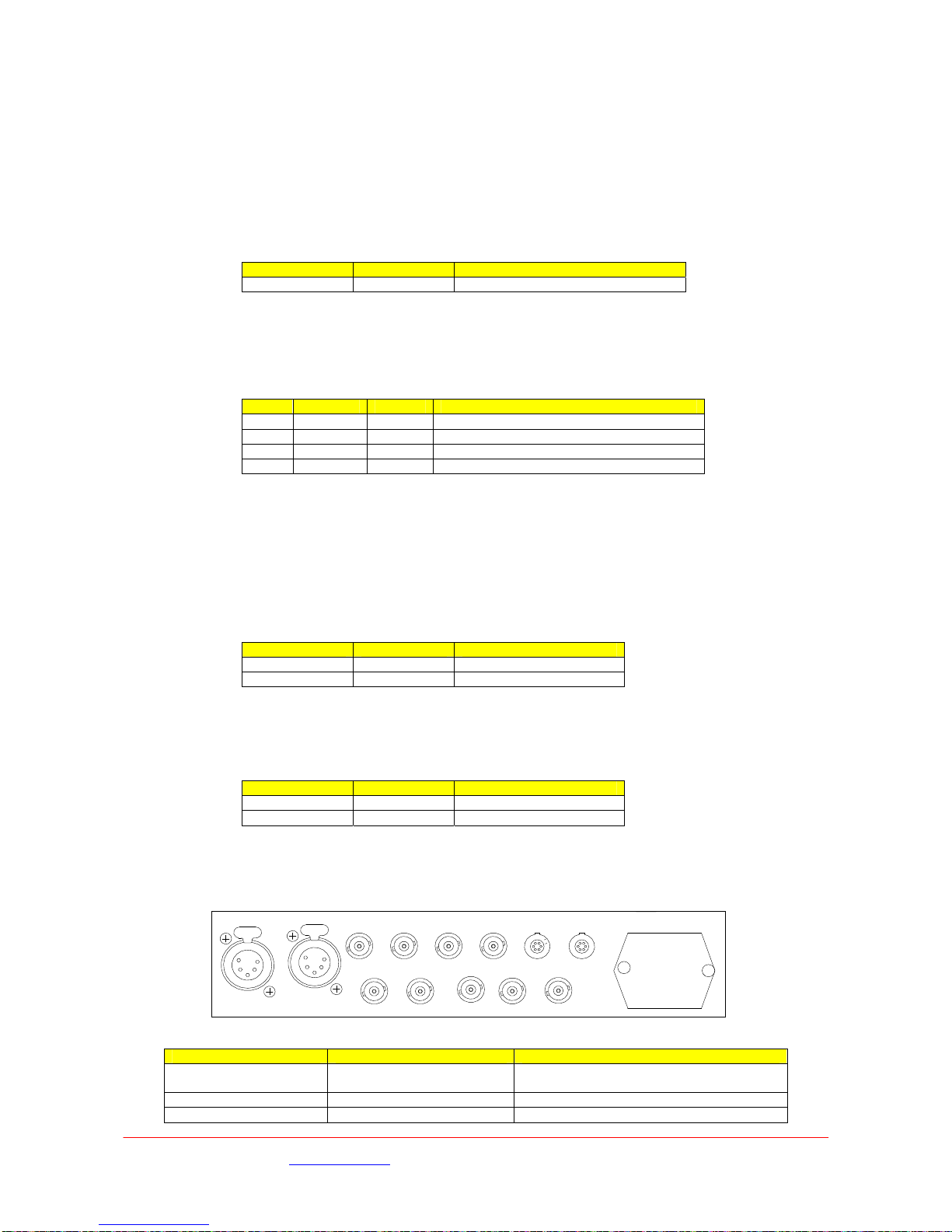
5.4 Connectors
All connectors are mounted on the rear panel of the unit.
ASI In
CH 1 CH 2
ASI Out SDI Out#1 SDI Out#2
F/Lock
Camera ControlRemote / DataRF 2RF 1 RF 3 RF 4
Connector type Legend Description
BNC 75Ωbayonet socket RF1 RF2 RF3 RF4 RF input, Power Out to the L3020.
Max input level -20dB
6 pin Lemo Remote/Data RS232 remote control and User data port
BNC 75Ωbayonet socket SDI Out #1 & #2 HD-SDI Video output (SMPTE 292M)
Images are for illustration only and may differ from components supplied
Link Research Ltd www.linkres.co.uk Support UK/Europe + (44) 1923 474099 USA +(1)9786715700
Page 20 of 31 CL140045 Issue C Link L1500 Series System Manual
Other manuals for L1500 Series
1
Table of contents
Other Link Camera Accessories manuals

Popular Camera Accessories manuals by other brands


Brinno
Brinno Pan Lapse quick start guide

Pentax
Pentax 67 Grip AF400T Bracket, Quick Focusing Ring operating manual

Pilotfly
Pilotfly H1 SE quick guide

Odyssey
Odyssey EnerSys PERFORMANCE Series Installation, operation and maintenance manual

Olympus
Olympus TL-Lite instruction manual

MICROTEX
MICROTEX Traction Power user guide