Link L1500 Series User manual

Images are for illustration only and may differ from components supplied
Link Research Ltd www.vislink.com Support UK/Europe + (44) 1442 431 410 USA +(1)978 671 5929
Page 1 of 21 CL140045 Issue F Link L1500 Series Manual
Link L1500 Series Manual
1. System Description 3
2. L1500 Transmitter 4
a. L1500 Display 5
b. L1500 Menus 6
c. Transmitter Setup 11
d. L1500 Connector Interface 14
e. L1520 Camera Control Module 14
f. L1500 HD Transmitter Description and Specification 15
g. Input / Output Connections 16
h. Mechanical 18
3. L1520 Camera Controller / Data Receiver – Optional 18
4. Maintenance & Firmware Upgrades 19
a. L1500 RF / Up Converter and Camera Control Module Removal 19
b. L1500 Firmware Upgrades 20
5. L1500 Product Part Numbers 21
6. Part Numbers for L1500 Accessories 21
Images are for illustration only and may differ from components supplied
Link Research Ltd www.vislink.com Support UK/Europe + (44) 1442 431 410 USA +(1)978 671 5929
Page 2 of 21 CL140045 Issue F Link L1500 Series Manual
Document Link L1500 HD Series Systems Manual
Issue Date Comments
A July 07 Working draft – based on LinkHD (L1400)
Manual
B Oct 07 Initial release
C Oct 07 Minor edits
D Dec 07 New menu features added for Tx, separate
L213x manual created.
E Dec 09 Added Deinterleaving
F Nov 10 Updated Link logo, Website and customer
support information. Removed L3020
downconverters and associated information.
Added L3025 downconverters. Updated
Supported camera manufacturers
information.
Safety and Compliance
Any mains power equipment must be earthed. Operate the equipment within environmental limits and
ensure as much ventilation as possible (Normally Temp 0C-50C <99% humidity). Only authorised
personnel should open the product and any repair or warranty will be invalidated if the seals are
broken. The equipment has been designed to be CE compliant and an EC Declaration of Conformity
and Technical files are available on request.
Please contact Link SUPPORT any issues.
Please ensure that normal anti-static precautions are taken when removing the L1500 modules from
the main unit.
Images are for illustration only and may differ from components supplied
Link Research Ltd www.vislink.com
1. System Description
The Link L1500 HD wireless radio camera system comprises of three main components :-
Link HD Transmitter - L1500+L1510* RF module
Link RF Down Converter (2 off) - L3025 (2GHz)
Link HD Receiver - L2132/4
*Note- In this manual L1510 is used to denote any of the optional RF / UpConverter modules.
Optional components for camera control :-
Link Wireless CCU Interface - L1255
Link HD Camera Controller - L1520
For a full list of supported camera manufacturers models go t our website
http://www.vislinknews.com/services-customer-support-supported-cameras.htm
Manufacturers include Ikegami, Sony, Thomson, Panasonic and Hitachi.
The basic system will include 3dBi Omni vertically polarized antenna for the transmitter and down
converters; a range of alternative antennas can be supplied to meet different operational
requirements.
These will provide the basic operation of the Link HD system although other configurations are
possible including diversity operation, through Triax and fibre etc.
Please contact Link Research Ltd for details.
Support UK/Europe + (44) 1442 431 410 USA +(1)978 671 5929
Page 3 of 21 CL140045 Issue F Link L1500 Series Manual
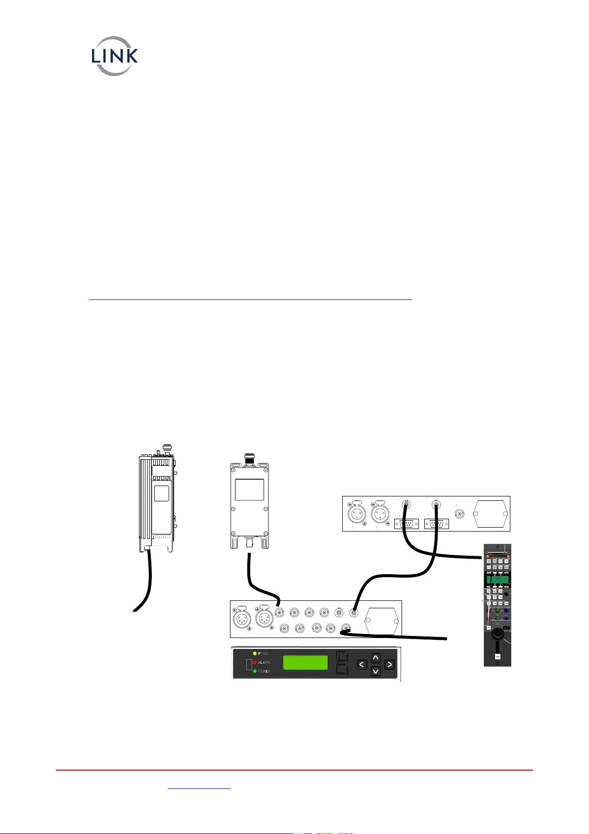
For basic operation, connections to the L1500 HD Transmitter unit are HD/SD video, analogue audio
and if required an RS232 data link. Power is supplied either via the attached battery plate or external
LEMO connector.
Max 4, Min 2
L3025
Downconverters
L2132/4 HD/SD
IRD Receiver
L1500 Encoder
Transmitter
HD/SD-Video
In
HD/SD SDI
or SD CVBS
TALLY A
Remote / Data
Receiver Interface
Antenna
OCP - Sony
OCP - RS232
TALLY B
L1255
interfacing into
OCP (option)
RF 3 RF 4RF 2RF 1 Camera
Control
Remote /
Data
ASI
In
CH
1
ASI
Out
SDI
Out#1
SDI
Out#2
F/Loc
k
CH
2

Images are for illustration only and may differ from components supplied
Link Research Ltd www.vislink.com
The power switch on the side of the L1500 is provided to switch the L1500 / L1520. This switch
cannot be used to control the supply to the forward camera interface plate which is always fed power
from the battery or external Lemo connector.
The L1500 can be supplied with various interface plates providing mounting of different batteries and
to different camera mounts - either IDX / Sony ‘V’ , PAG Loc or Anton Bauer Gold Mount are available.
Adaptor brackets are also available to allow mounting of the L1500 to the rear of Thompson LDK6000
series of cameras and the Sony 1500 series. These interface plates provide a ‘quick release’ to
remove the transmitter from the camera
A full list of accessories and cables is given at the end of this document
2. L1500 Transmitter
The L1500 Series Encoder/Transmitter is a compact HD/SD MPEG2 Encoder, DVB-T and LMS-T
modulator and 100mW output power amplifier (250mW FCC only). LMS-T is a unique robust
modulation scheme developed specifically for wireless camera use.
Camera Control Module
– L1520
RF Module /Up Converter
Module – L1510
Camera Interface
Battery
Interface
Control
Panel
Support UK/Europe + (44) 1442 431 410 USA +(1)978 671 5929
Page 4 of 21 CL140045 Issue F Link L1500 Series Manual
Images are for illustration only and may differ from components supplied
Link Research Ltd www.vislink.com
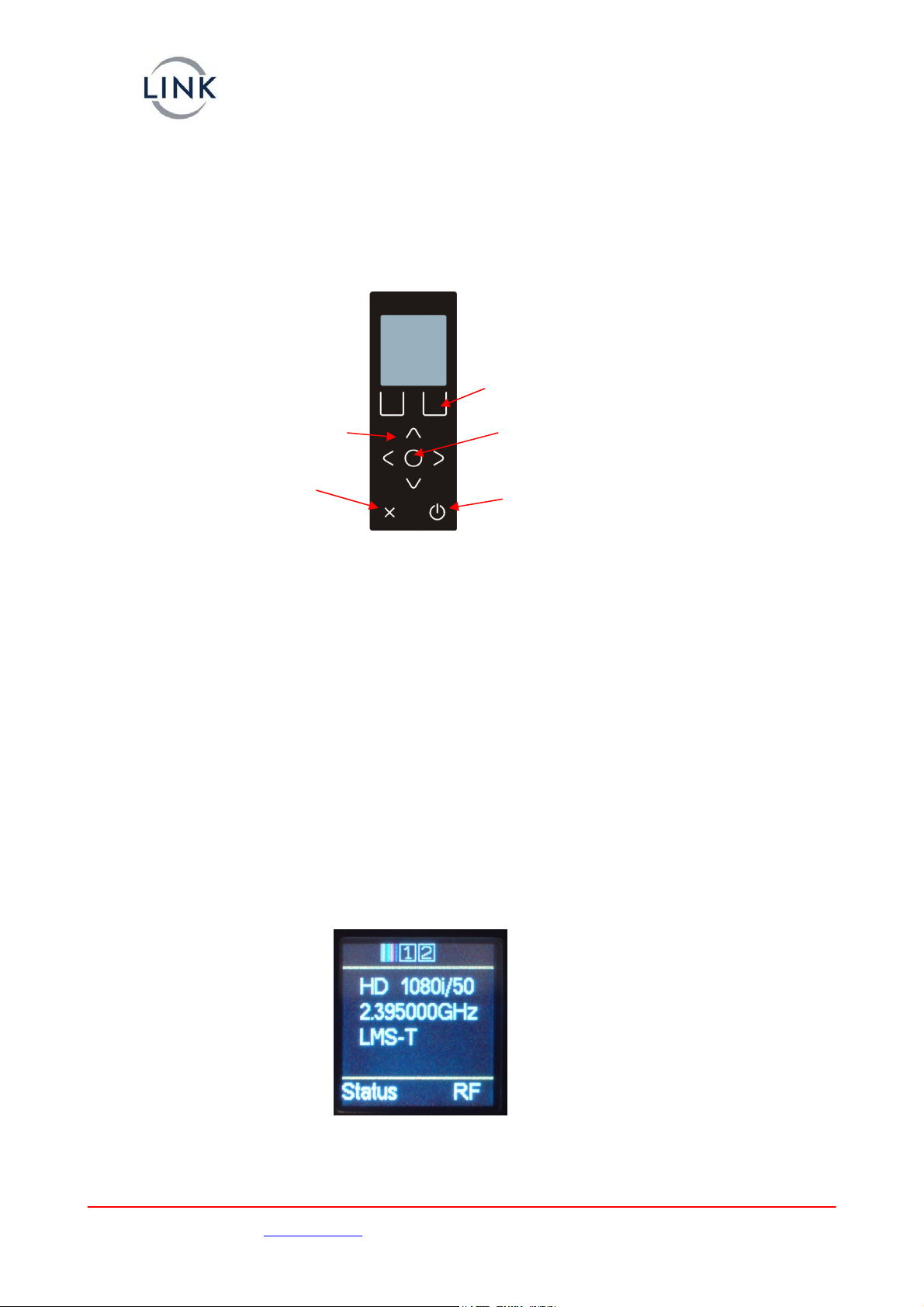
The L1500 is configured by the operator using the menu structure displayed on the colour LCD
display, 9 membrane push buttons are used to navigate through these menus and select the required
data. Please see bbelow for details of the L1500 menu structure.
‘Enter’
‘Power’
U
p
/ Down / Left /Ri
g
ht
‘Cancel’ / ‘Exit’
Function ke
y
s
–
action de
p
ends u
p
on
p
osition within menu
The left / right and up / down buttons are used to select the required menu, or sub-menu the
Enter selects highlighted option which can then be modified with the up / down buttons.
Enter will then select the option or Cancel (‘X’) will exit back to the level above without selecting or
changing the settings..
Two Function keys are also available and can provide ‘short cuts’ into various functions without
navigating through the menu structure.
The ‘Status’ display can be used to display the battery voltage and current consumption of the L1500
unit.
The ‘RF’ function key is used to toggle the RF output on / off without the need to enter the sub
menus.
A single ’soft’ Power switch is also provided to control the L1500 unit. This switch must be pressed
for ~3secs to switch the L1500 on or off. This is to avoid accidental switching of the unit due to
nocking the power switch.k
When power is applied to the L1500 it will revert to the condition when the power was removed.
E.g. If the L1500 was off when the power was removed; the power switch will need to be pressed to
turn the unit on. If the L1500 was on when the power was removed the unit will automatically power
on.
a. L1500 Display
i. Status Display
The ‘normal’ status display gives confirmation of the main operating configuration of the L1500 unit.
video format , transmit frequency and RF modulation mode.The
Support UK/Europe + (44) 1442 431 410 USA +(1)978 671 5929
Page 5 of 21 CL140045 Issue F Link L1500 Series Manual
Images are for illustration only and may differ from components supplied
Link Research Ltd www.vislink.com
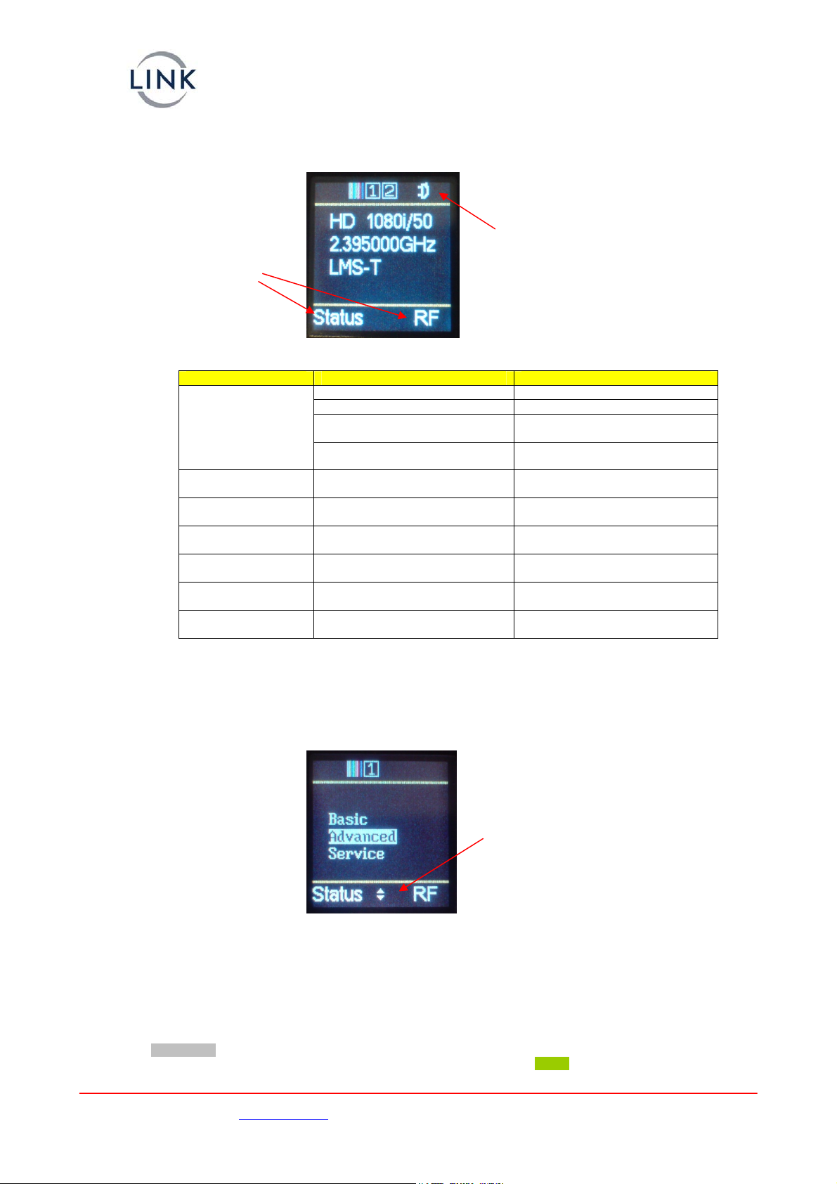
ii. Icons
The top line of the display shows various icons that give information about the configuration of the
L1500.
‘Function’ key definition
Example of Icons showing :-
Bars On, Audio1 On, Audio2 On, Remux On
Icon Condition Format
RF On Icon with green background
RF off Not displayed
Carrier On Icon with flashing green
background
Tx Icon
Sideband on Icon with flashing orange
background
Bars Icon Video loss has bars selected
Colour stripes
Audio Ch1 Icon Audio Enabled
White ‘1’ symbol on black
background.
Audio Ch2 Icon Audio Enabled
White ‘2’ symbol on black
background.
Video Icon Video lock detected White Camera symbol on black
background
Remux Icon Remux enabled White ‘And’ gate symbol on black
background
Remux Icon Remux active White ‘And’ gate symbol on
flashing green background
Pressing the Enter button will enter the top level menu where either of the three sub menus can be
selected.
Arrow indicating further options available by scrolling
up / down through the menu
Example of a sub menu showing the use of highlighted options to show the currently selected item.
The arrows on the lower line of the display indication whether further items are available by scrolling
up or down from the current position.
b. L1500 Menus
The Greyed Out parameters not available with the current version of code.
Some functions are only available in HD mode; these are highlighted in Green shading.
Support UK/Europe + (44) 1442 431 410 USA +(1)978 671 5929
Page 6 of 21 CL140045 Issue F Link L1500 Series Manual

Images are for illustration only and may differ from components supplied
Link Research Ltd www.vislink.com Support UK/Europe + (44) 1442 431 410 USA +(1)978 671 5929
Page 7 of 21 CL140045 Issue F Link L1500 Series Manual
The table below is split into the three ‘Levels’ corresponding to BASIC, ADVANCED and SERVICE levels
y a competent operator; the normal operational functions can then be changed at
he SERVICE functions are intended for diagnostics and servicing by a technician / engineer.
BASIC S
of operation.
The BASIC functions are also included in the ADVANCED level, this is to allow all functions of the unit
to be configured b
the BASIC level.
T
i. FUNCTION
Options Function Comment
Modulator Frequency dependent on module le detected and NOT in
SI mode
Range
fitted
Only if modu
A
RF t 10,50,100,250mWOutpu
Level
RF Output On/Off
Mod. Mode QPSK,16QAM,64QAM
Video Source Video Input 1080i/50,720p30 etc etc ons dependent on either SD or
D
Opti
H
Test Pattern On/Off
Video Loss Bars, Blank, Bars+Audio video input detected sets Bars
n
If no
O
Audio Ch1 dEnable On/Off
Input
’s
Analogue, Test Tone,
Embedded, Channel ID
Mic/Line Mic or Line level input gain & optionalMic adds +25dB
Phantom Power
On / Off Only if Mic is selectedPhantom
Power
Level Left Sets required gain
Level Right
Audio Ch2 As Ch1
Status Temperature Display units internal temp
Service Name its currentDisplay / set un
Service Name
Display units serial number quiriesSerial
Number
Should be quoted in all en
with service department
Licence Code Allows entry of licence code Tied to serial number of unit
Camera
Control
Camera Type Selects camera type in use
Frequency Sets UHF receiver frequency

Images are for illustration only and may differ from components supplied
Link Research Ltd www.vislink.com Support UK/Europe + (44) 1442 431 410 USA +(1)978 671 5929
Page 8 of 21 CL140045 Issue F Link L1500 Series Manual
ii. ADVANCED FUNCTIONS
Options Function Comment
System Auto Set Service 1… Sets PID information for multiple
camera operation
Restore default Yes / No Sets unit configuration to Default
values
Save Profile 1… Stores current configuration
Load Profile Yes / No Loads saved configuration
Save to Stick Yes / No Saves all profiles to USM memory
stick
Load from Stick Yes / No Loads all profiles from USB memory
stick
Contrast 30-50 Used to adjust display contrast,
lower the value=increased contrast.
Unit Fans On/Off/Auto Control units fans
Modulation Frequency Range dependent on
module fitted
Only if module detected
RF Output Level 10,50,100,250mW
RF Output On/Off
Mod. Mode QPSK,16QAM, 64QAM LMS-T QPSK & 16QAM only
Mod. Type LMS-T, DVB-T
Guard Interval 1/32 ….
FEC ½ ……
Bandwidth 6,7,8,10 & 20MHz …. LMS-T 10 & 20MHz; DVB-T 6,7,8MHz
Mod. Polarity Normal, Invert
Delivery Desc On/Off
OFDM Offset +/- 4KHz, none Allows 4KHz offset to COFDM
Multiplexer ASI Packet Off,188,204 bytes
ASI Bit Rate 10.000Mb/s Display / set output bit rate
Service Name ‘Any text’
Network Name ‘Any text’
PMT PID Sets PID 0 - 9999
PCR PID Sets PID 0 - 9999
Local Service On, Off
Program ID Sets ID 0 - 9999
Network ID Sets ID 0 - 9999
TS ID Sets ID 0 - 9999
Video Encoder Video Input 1080i/50,720p30 etc etc Options dependent on either SD or
HD
Test Pattern On/Off
Video Loss Blank,Bars,Bars+Audio Bars with or without tone
Percentage 75%,100% Selects required Bars type
Bars Text On,Off Adds scrolling ‘Service Name’ test
SD / HD HD / SD Selects either SD or HD video input
formats
Encoder On / Off Turns of local encoder
Auto Bit Rate On / Off Encoder set to maximum rate for TS
or modulation setting
Enc Bit Rate 12.456Mb/s Shows current bit rate. If NOT auto
bit rate sets encoder bit rate setting.
MPEG 4:2:0 / 4:2:2
GOP Length 8…. Sets required GOP Length
Video PID 0-9999 Sets required Video PID
Enc Mode Std / Low Delay Only if SD encoder
Audio Ch1 Enabled On/Off
Input Test Tone, Analogue,
Embedded
Mic/Line Mic or Line level input Mic adds +25dB gain & optional
Phantom Power
Phantom power On/Off Only if Mic selected
Level Left Sets required gain
Level Right
Type MPEG L1,L2, Linear
Bit Rate 320Kbs
Mode Dual Mono, Stereo
Language Eng, Fre,Ger,Spa
Tone Level -18dBFS Sets output level of Test Tone
PID 0-9999

Images are for illustration only and may differ from components supplied
Link Research Ltd www.vislink.com Support UK/Europe + (44) 1442 431 410 USA +(1)978 671 5929
Page 9 of 21 CL140045 Issue F Link L1500 Series Manual
DID 0-9999
HD DID 0-9999
Audio Ch2 As Ch1
Remux Enable On, Off Turns the remux (external ASI input)
on / off
Rxd Input Rate 12.456Mb/s Display incoming ASI rate
Status Not Active Shows condition of remux input
Scrambling Scrambling Off,BISS-1,EBS
Key *********** Enter required encryption key
RS232 Data Data On, Off, Low delay, TTV
Baud Rate 9600
Data PID 0-9999
iii. SERVICE FUNCTIONS
Options Function Comment
Encoder Serial Number PCB serial number Should be quoted in all enquiries with
service department
Licence Code Allows Licence code
changes
Defines units enabled features
*Caution-if an invalid code is
entered the unit will become in-
operable *
Software Revision 1a2 Displays Encoder firmware revision
Enc Temp 45.5degC Display encoder temperature
Module1 Status Not Fitted Camera Control – if fitted
Module2 Status Health of module 0001 - OK
Type 2.5GHz Type of module fitted
PA Temperature 46degC PA temperature
Build Rev 1a2 Displays module firmware revision
Serial Number PCB serial number
Carrier Only On/Off Provided for test purposes-normal OFF
RF Power Control On/Off Provided for test purposes-normal ON
RF Atten Read only Provided for test purposes
RF Scaling Read only Provided for test purposes
PA On/Off On/Off
Sideband On/Off On/Off Provided for test purposes
Sideband Pol Norm/Inv Provided for test purposes
Sideband Freq 2,4,8MHz Provided for test purposes
Versions Unit Version V005 Main unit firmware release-USB stick
file
Code Version V1_06 Main menu firmware version
Kernel Version V1_04 Linux Kernel version
Encoder Version 3b19 Encoder firmware
FP FPGA V00_d Front Panel FPGA
UC Version V00_06 L1510 (UpConvertor) firmware
CC Version n/a L1520 (Camera Control) firmware
FP PIC V10_03 Front Panel version
Enc PIC V10_02 Encoder PIC version
Serial Number 12345678 Encoder PCB serial number
Licence Mask 000fa0ec Defines which features are licensed
Cust. Support Contact Details

Images are for illustration only and may differ from components supplied
Link Research Ltd www.vislink.com Support UK/Europe + (44) 1442 431 410 USA +(1)978 671 5929
Page 10 of 21 CL140045 Issue F Link L1500 Series Manual
iv. Default Settings
Following a ‘Restore Factory Defaults’ (Advance/System/Restore Defaults) it will be necessary to
select the required operating mode and modulation configuration. This will take several seconds to
update all the sub systems within the L1500.
If the unit is licensed for HD operation it will default to HD, else it will default to SD operation.
The default settings are :-
System Auto Set Service 1
Unit Fans On
Modulation Frequency 2.395MHz
RF Output Level 100mW
RF Output Off
Mod. Mode 16QAM
Mod. Type LMS-T
Guard Interval 1/16
FEC 2/3
Bandwidth 10MHz
Mod. Polarity Normal
Multiplexer ASI Packet 188bytes
ASI Bit Rate 19.5156Mb/s
Service Name Service01
Network Name Net 1
PMT PID 0256
PCR PID 0512
Local Service On
Program ID 0001
Network ID 0001
TS ID 0001
Video Encoder Video Input 1080i/50
Test Pattern Off
Video Loss Bars
SD / HD HD
Encoder On
Auto Bit Rate On
Enc Bit Rate 18.7419Mb/s
MPEG 4:2:2
GOP Length 12
Video PID 0512
Audio Ch1 Enabled On
Input Analogue
Mic/Line Mic level
Phantom Power On
Level Left 31.5dB
Level Right 31.5dB
Type MPEG L1
Bit Rate 224Kbs
Mode Stereo
Language Eng
Tone Level -18dBFS
PID 4112
DID 767
Audio Ch2 Enabled Off
Remux Enable Off
Rxd Input Rate 0Mb/s
Status Not Active
RS232 Data Data Off
Baud Rate 9600
Data PID 0100

Images are for illustration only and may differ from components supplied
Link Research Ltd www.vislink.com Support UK/Europe + (44) 1442 431 410 USA +(1)978 671 5929
Page 11 of 21 CL140045 Issue F Link L1500 Series Manual
c. Transmitter Setup
i. Modulator
It is important that when changing between modes of operation it is necessary to check and re-select
certain operating parameters due to interaction of some of these parameters.
For example when changing from DVB-T to LMS-T mode it will be necessary to reset the required
modulation scheme.
In the following examples the menus are described by :-- Level / Sub Menu / Function.
Some of the settings can be made from either the BASIC or the ADVANCED menus; the more
‘complex’ are only available from the ADVANCED level.
1. DVB-T Operation
The following sequence defines the changes and sequence required when changing to DVB-T
operation :-
Step Menu Sub Menu Option Setting
1 Advanced Modulation Modulation Type DVB-T
2 Advanced Modulation Guard Interval Must match
receiver
3 Advanced,Basic Modulation Modulation Mode As Required
4 Advanced Modulation FEC Rate As Required
5 Advanced Modulation Polarity Must Match
Receiver
6 Advanced Modulation BandWidth Fixed at 8MHz
7 Advanced,Basic Modulation Power As Required
8 Advanced,Basic Modulation Frequency As Required
9 Advanced,Basic Modulation RF Output On
The MPEG2 encoder will set the data rate appropriately to match the modulation scheme settings.
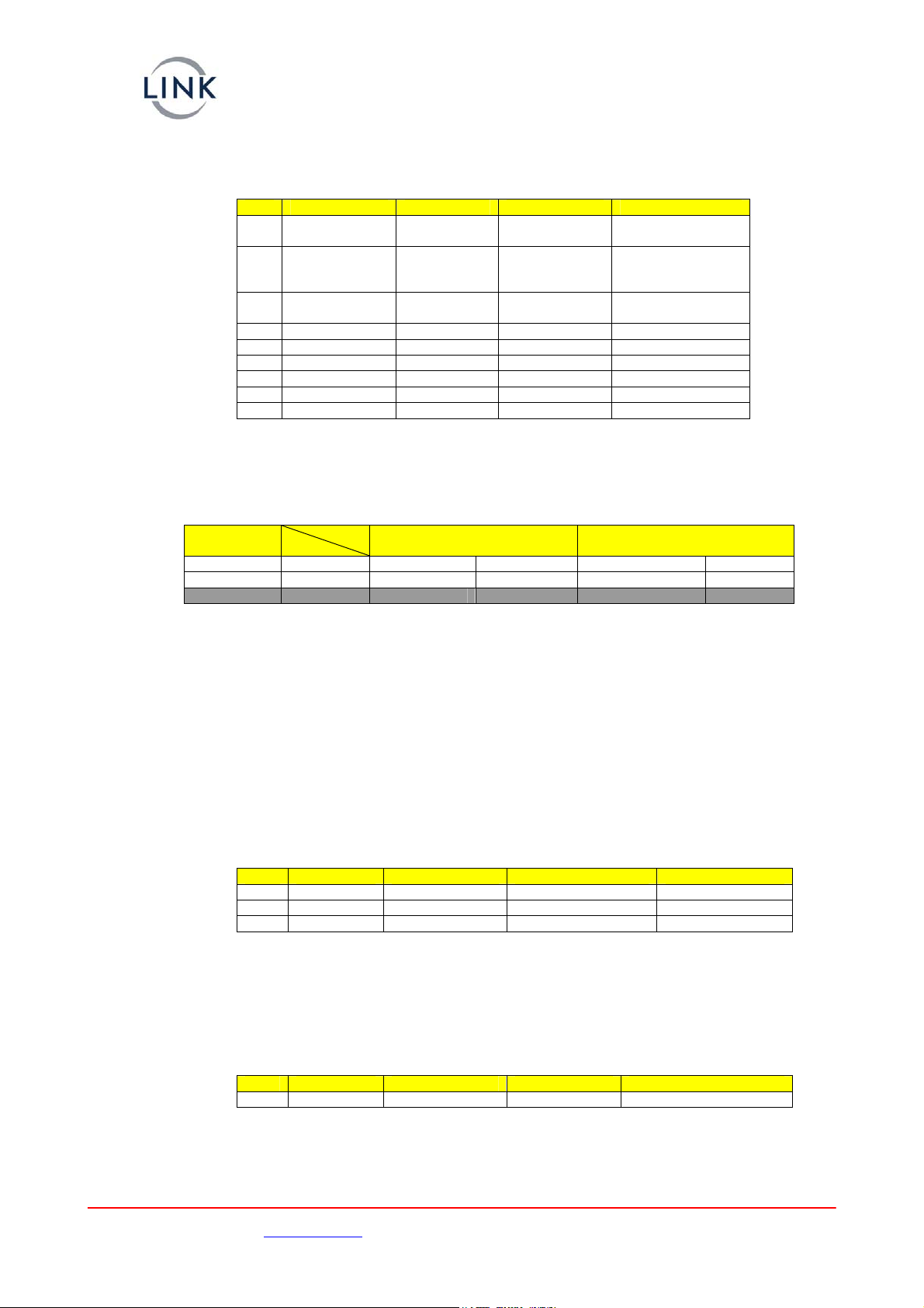
The Table below defines the corresponding bit rates for DVB-T operation.
Modulation GI
CR
1/4 1/8 1/16 1/32
QPSK 1/2 4.97 5.52 5.85 6.03
QPSK 2/3 6.63 7.37 7.80 8.04
QPSK 3/4 7.46 8.29 8.78 9.04
QPSK 5/6 8.29 9.21 9.75 10.05
QPSK 7/8 8.70 9.67 10.24 10.55
16QAM 1/2 9.95 11.05 11.70 12.06
16QAM 2/3 13.27 14.74 15.61 16.08
16QAM 3/4 14.92 16.58 17.56 18.09
16QAM 5/6 16.58 18.43 19.51 20.10
16QAM 7/8 17.41 19.35 20.49 21.11
64QAM 1/2 14.92 16.58 17.56 18.09
64QAM 2/3 19.90 22.11 23.41 24.12
64QAM 3/4 22.39 24.88 26.34 27.14
64QAM 5/6 24.88 27.64 29.27 30.16
64QAM 7/8 26.12 29.02 30.73 31.66
The selections greyed out are available in the transmitter , but not in the current version of the
receiver firmware. Check Support for updates.
These rates can be confirmed by checking the Advanced/Multiplexer/ Bit Rate menu.
It should be noted that this corresponds to the total data rate from the multiplexer which includes the
video, audio and any user data.
Images are for illustration only and may differ from components supplied
Link Research Ltd www.vislink.com Support UK/Europe + (44) 1442 431 410 USA +(1)978 671 5929
Page 12 of 21 CL140045 Issue F Link L1500 Series Manual
2. LMS-T Operation
The following sequence defines the changes and sequence required when changing to LMS-T
operation :-
Step Menu Sub Menu Option Setting
1 Advanced Modulation Modulation
Type
LMS-T
2 Advanced Modulation Guard Interval As Required. 1/8
or 1/16. Must
match receiver
3 Advanced,Basic Modulation Modulation As Required 16Q
or QPSK
4 Advanced Modulation FEC Rate 2/3 Only
5 Advanced Modulation Polarity Normal
6 Advanced Modulation Width 10MHz or 20MHz
7 Advanced,Basic Modulation Power As Required
8 Advanced,Basic Modulation Frequency As Required
9 Advanced,Basic Modulation RF Output On
The encoder will set the data rate appropriately to match the modulation scheme settings.
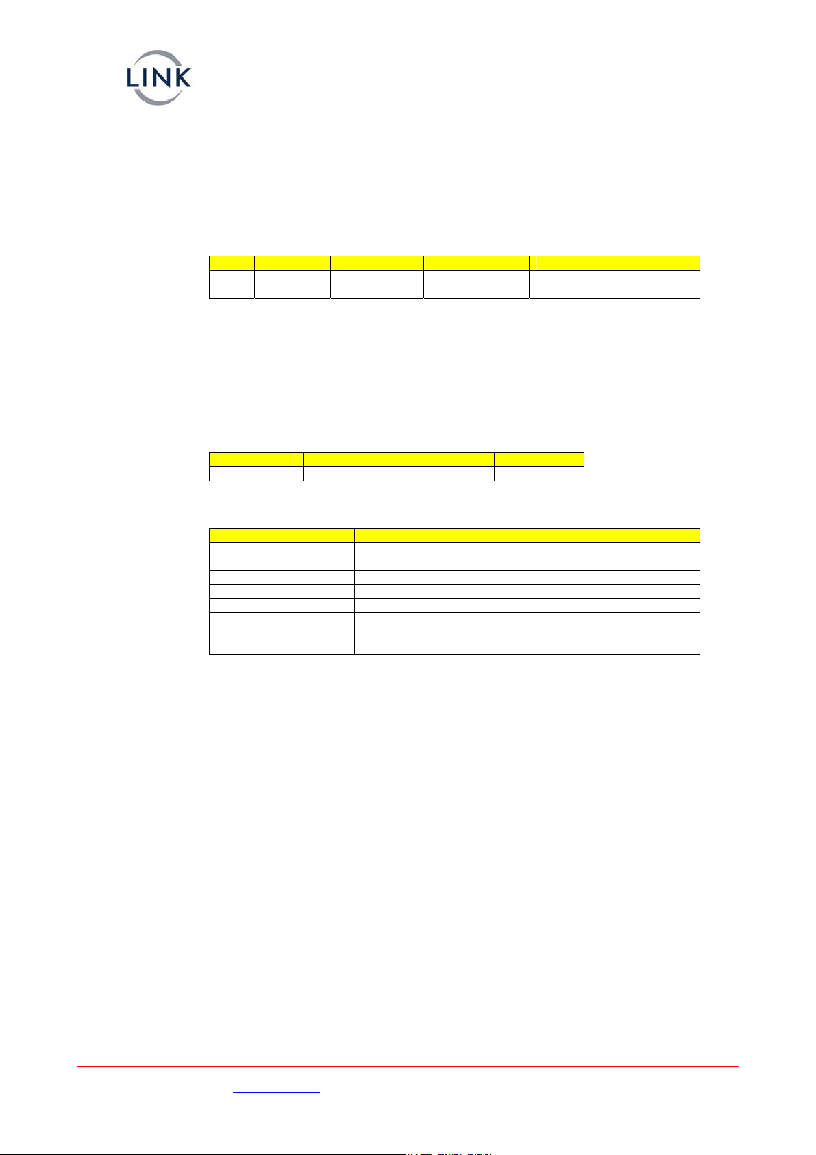
The Table below defines the corresponding bit rates for LMS-T operation for both 10MHz and 20MHz
operation.
Modulation GI
CR
1/8
10MHz 20MHz
1/16
10MHz 20MHz
QPSK 2/3 9.2 18.4 9.7 19.5
16QAM 2/3 18.4 36.8 19.5 39
64QAM 2/3 27.6 45.2 29.2 58.5
Note 64 QAM not available on current software.
These rates can be confirmed by checking the Advanced/Multiplexer/Bit Rate menu.
It should be noted that this corresponds to the total data rate which includes the video, audio and any
user data.
Due to the improvement that LMS-T has over DVB-T these settings give approximately 50%
improvement of bit rates for the same level of ruggedness of the RF link.
For example DVB-T 16QAM, 1/32 GI, 1/2 CR gives 12Mbits whereas LMS-T 16QAM gives 18Mbits
3. ASI Operation
The L1500 can be used as an MPEG2 HD encoder providing an ASI output. The modulator and RF Up
converter are not required in this operating mode.
This provides ASI streams up to 90Mbits.
Step Menu Sub Menu Option Setting
1 Advanced Modulation Modulation Type ASI
2 Advanced Multiplexer ASI Bit Rate As Required
3 Advanced Video Encoder Bit Rate As Required
The encoder bit rate cannot be set above the Mux bit rate, if an attempt is made to exceed the mux
setting the encoder value will clamp to the highest allowed rate.
4. Remux Operation
The L1500 can be used to re-multiplex an additional service into the ASI data stream. This allows two
services can be transmitted on one RF Channel.
Step Menu Sub Menu Option Setting
1 Advanced Remux Enable On
It is important that the remultiplexed service multiplexer rate and the internal generated service
multiplexer data rate are within the available RF modulated data rate.
Images are for illustration only and may differ from components supplied
Link Research Ltd www.vislink.com Support UK/Europe + (44) 1442 431 410 USA +(1)978 671 5929
Page 13 of 21 CL140045 Issue F Link L1500 Series Manual
5. Interleaving Operation
The L1500 has a licensable interleaving option. This option adds an extra layer of error correction to
the ASI data steam that allows long breaks in RF reception to be corrected. The user can select the
amount of FEC used and the duration of RF break that can be corrected. Adding interleaving to an ASI
stream reduces the ASI bit rate available for video/audio etc. and adds a delay to the signal. The
additional delay is shown in the menu and the effect on the bit rate can be seen in Advanced/Video
Encoder/Bit Rate.
The L1500 is capable of deeper interleaving than the L2134 supports. Interleaving depths that are not
supported are shown as 0 ms on the L2134 front panel for either burst or delay.
Step Menu Sub Menu Option Setting
1 Advanced Multiplexer Interleave FEC Off, 1/2, 2/3 ... 7/8, 14/15
2 Advanced Multiplexer Interleave Burst 1 … 2000 ms
Link’s interleaving scheme does not touch the encoded bit stream from the transmitter other than to
add extra data. It is this extra data that is interleaved. This effect of this is that when a break in RF
occurs that is longer than the set burst length, then the break in signal seen at the receiver is the
same as the original RF break.
ii. Video
It is important that the encoder is configured to match the incoming video format. The rates MUST
match otherwise the encoder may appear to operate correctly but then fail with changing video
images.
Menu Sub Menu Option Setting
Advanced Video HD Input Unit As required
iii. Audio
Step Menu Sub Menu Option Setting
1 Advanced Audio A or B Type Encoding as required
2 Advanced,Basic Audio A or B Input As Required
3 Advanced Audio A or B Bit Rate As Required
4 Advanced Audio A or B Mode As Required
5 Advanced,Basic Audio A or B Line / Mic As required
6 Advanced,Basic Audio A or B Phantom Pwr If Mic selected
7 Advanced,Basic Audio A or B Mic or Line
Level
Set required gain
Images are for illustration only and may differ from components supplied
Link Research Ltd www.vislink.com
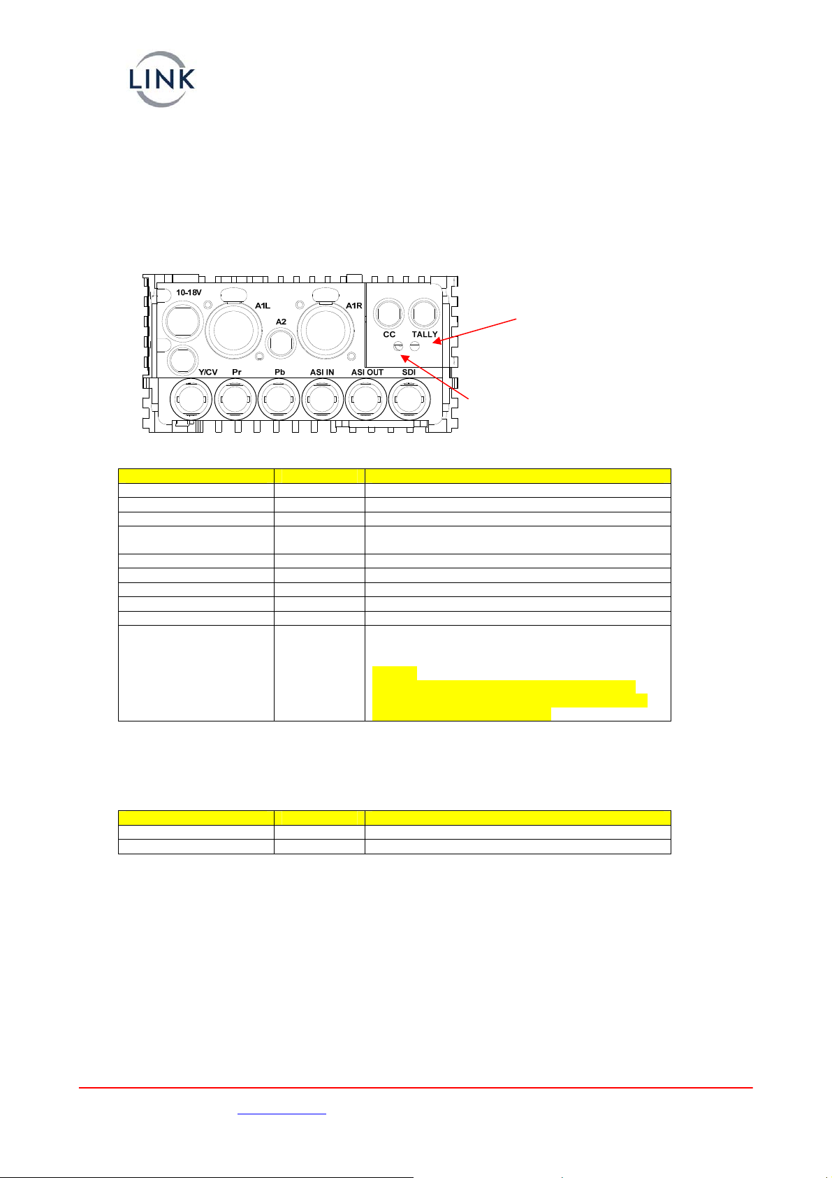
d. L1500 Connector Interface
Top Panel Connector RF out N Type Male 50 ohm connector.
Side Panel Connectors USB, serial interface used for firmware upgrades etc
Lower Panel Connectors Position of panel connectors on the L1500 transmitter.
DATA
RF receiver locked
Data decoder locked
Connector type Legend Description
BNC 75Ωbayonet socket SDI In SD/ HD-SDI (SMPTE 259M / SMPTE 292M)
BNC 75Ωbayonet socket ASI OUT DVB-ASI – output from the MPEG2 encoder
BNC 75Ωbayonet socket ASI IN DVB-ASI – into the Remux for modulation
BNC 75Ωbayonet socket Y/CV PAL or NTSC (625 / 525) SD only, also Y for SD
component
BNC 75Ωbayonet socket Pr Component SD only
BNC 75Ωbayonet socket Pb Component SD only
XLR3 Female A1L / A1R Ch1 Analogue audio inputs. Line or Mic level
6 way LEMO A2 Ch2 Analogue audio inputs. Line or Mic level
6 way LEMO DATA RS232 connection for Link Control
4 way LEMO PWR External 12V battery supply if rear ‘clip on’ battery
is not used.
It is also possible to take power from the ‘clip on’
battery.
Care must be taken to ensure that the ‘clip on’
battery on the rear of the L1500 is not ‘back fed’
by an external battery or power supply.
e. L1520 Camera Control Module
Connector type Legend Description
5 way LEMO CC Data Serial data interface to / from camera
6 way LEMO Tally Interface for external Tally light
Support UK/Europe + (44) 1442 431 410 USA +(1)978 671 5929
Page 14 of 21 CL140045 Issue F Link L1500 Series Manual

Images are for illustration only and may differ from components supplied
Link Research Ltd www.vislink.com
f. L1500 HD Transmitter Description and Specification
The complete transmitter unit contains three main assemblies which can provide a flexible and
upgradeable transmitter system:-
•Main unit, contains encoder, audio pre-amps, display and controller
•Modular RF Up Converter, available in various frequency bands
IQ Up Conv. &
Power Amp.
Front Panel
Support UK/Europe + (44) 1442 431 410 USA +(1)978 671 5929
Page 15 of 21 CL140045 Issue F Link L1500 Series Manual
•Camera Controller (optional) or a ‘dummy’ unit must be fitted
i. Video Formats
The L1500 transmitter unit will accept HD-SDI inputs in any of the following HD formats :-
Standard
Total
lines
per
frame
Total
samples
per line
Active
lines
per
frame
Active
samples
per line
Interlace
or
Progressive V freq H freq
1080/60I 1125 2200 1080 1920 I 60 Hz 33.75 KHz
1080/59.9I 1125 2200 1080 1920 I 60/1.001 33.716 KHz
1080/50I 1125 2640 1080 1920 I 50 Hz 28.125 KHz
1080/30P 1125 2200 1080 1920 P 30 Hz 33.75 KHz
1080/29.9P 1125 2200 1080 1920 P 30/1.001 33.716 KHz
1080/25P 1125 2640 1080 1920 P 25 Hz 28.125 KHz
1080/24P 1125 2750 1080 1920 P 24 Hz 27.0 KHz
1080/23.9P 1125 2750 1080 1920 P 24/1.001 26.973 KHz
1080/60P 1125 2200 1080 1920 P 60 Hz 33.75 KHz
1080/50P 1125 2640 1080 1920 P 50 Hz 28.125 KHz
1080/24PsF 1125 2750 1080 1920 SF 48 Hz 27.0 KHz
1080/23.9PsF 1125 2750 1080 1920 SF 48/1.001 26.973 KHz
720/60P 750 1650 720 1280 P 60 Hz 45 KHz
720/59P 750 1650 720 1280 P 60/1.001 44.955 KHz
720/50P 750 1980 720 1280 P 50 Hz 37.5 KHz
Encoder
Line
Audio
Mic
UHF
Radio
Modem
Camera
Controller
SDI
Analogue
Audio
Camera
Control
Data
ASI in
ASI
Option
Display &
Keypad
SD
Analo
IQ
g
ue
Ret. Data

Images are for illustration only and may differ from components supplied
Link Research Ltd www.vislink.com Support UK/Europe + (44) 1442 431 410 USA +(1)978 671 5929
Page 16 of 21 CL140045 Issue F Link L1500 Series Manual
The L1500 will also accept SD inputs as either composite (CVBS), component (Y/Pr/Pb) or SDI in
the following formats :-
Standard
Input
Connector
SDI 625 SDI
SDI 525 SDI
PAL CV
NTSC CV
NTSC No Ped CV
PAL-M CV
PAL-N CV
YPbPr 625 Y/Pr/Pb
YPbPr 525 Y/Pr/Pb
Betacam Y/Pr/Pb
g. Input / Output Connections
This following section details the connector types and pin-outs of the interface connectors on the
L1500 Transmitter unit.
i. SDI Video Input
75Ωchassis mounted BNC jack socket for input of HD-SDI (SMPTE 292M) or SD-SDI (SMPTE 259M)
video.
ii. SD Analogue Video Inputs
Three 75Ωchassis mounted insulated BNC jack sockets for input of composite (CV) or component
analogue (YPrPb) SD video. The CV and Y inputs share a common connector.
iii. ASI
Both ASI input and ASI output are connected to the transmitter unit via 75Ωchassis mounted BNC
jack sockets.
iv. Audio - Ch1
A stereo pair, differential inputs at Mic level (with or without phantom power) or Line Level. A
switched 25dB gain and a variable (+31.5 to -95dB) level control.
Line / Mic and phantom power is independently switchable on Ch1 and Ch2.
>20kΩinput impedance
Frequency response 50Hz to 15kHz <0.1dB
Frequency response 20Hz to 20kHz <0.5dB
+18dB clipping level (+18db ≡0dBFS)
2 Chassis Socket Connectors:- XLR3
XLR Pin Function
Pin 1 Gnd
Pin 2 Live / +ve
Pin 3 Ret / -ve
v. Audio - Ch2
A stereo pair, differential inputs at Mic level (with or without phantom power) or Line Level.
A switched 25dB gain and a variable (+31.5 to -95dB) level control.
Line / Mic and phantom power is independently switchable on Ch1 and Ch2.
>20kΩinput impedance
Frequency response 50Hz to 15kHz <0.1dB
Frequency response 20Hz to 20kHz <0.5dB
+18dB clipping level (+18db ≡0dBFS)
Chassis Socket Connector :- LEMO EEG0B305CLV
Mating Cable Plug :- LEMO FGG0B305CLAD52Z
Link Cable Assembly – 2 x XLR3 :- L0001
Images are for illustration only and may differ from components supplied
Link Research Ltd www.vislink.com Support UK/Europe + (44) 1442 431 410 USA +(1)978 671 5929
Page 17 of 21 CL140045 Issue F Link L1500 Series Manual
LEMO Pin Function
Pin 1 Left Line + (Line)
Pin 2 Left Line - (Return)
Pin 3 GND
Pin 4 Right Line + (Line)
Pin 5 Right Line - (Return)
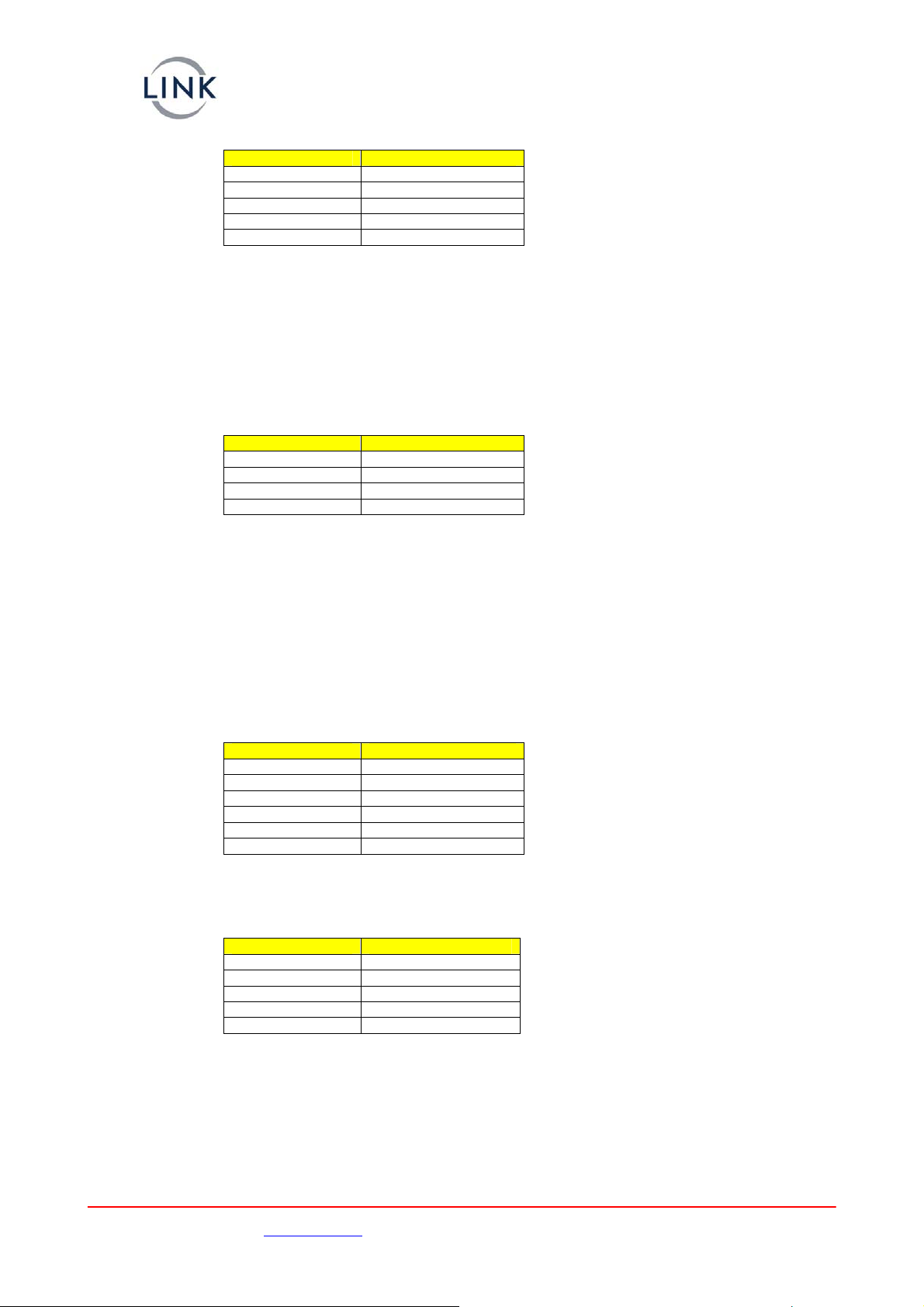
vi. DC Power
L1500 ~28W 12V DC nominal (10V minimum, 18V maximum)
Power dependent upon frequency of L1510, RF output power and camera control options.
Performance is degraded below 11.0V.
Chassis Socket Connector :- LEMO ECG1B304CLV
Mating Cable Plug :- LEMO FGG1B304CLAD62Z
Link Cable Assembly– flying leads :- L0003
LEMO Pin Function
1 GND
2 GND
3 +12V supply
4 +12V supply
vii. RF
100mW into 50Ω– switchable. 10, 50 ,100 and 250mW.
Note:- 250mW is for use in FCC regulatory regions only.
50Ωchassis mounted ‘N’ type bulkhead socket.
viii. RS232 Data & Control Port
The six pin connector provides the RS232 input / output of both the User Data and also Remote
Control of the transmitter unit.
Chassis Socket Connector :- LEMO EEF0B306CLV
Mating Cable Plug :- LEMO FGG0B306CLAD52Z
LEMO Pin Function
Pin 1 Tx Data (output)
Pin 2 Rx Data (input)
Pin 3 0v
Pin 4 Tx Control (output)
Pin 5 Rx Control (input)
Pin 6 0v
ix. USB Data Port
A USB2 ‘Mini B’ style connector is to allow for serial communication with the unit.
Chassis Socket Connector :- Molex 67503-0020
USB Pin Function
Pin 1 Vbus
Pin 2 D-
Pin 3 D+
Pin 4
Pin 5 0V

Images are for illustration only and may differ from components supplied
Link Research Ltd www.vislink.com
h. Mechanical
FROM SURFACE)
DEPTH 8.0mm
(MAX THREAD
4-M3 HOLES
LOOSE PIECE
LOOSE PIECE
3.00
8.75
140.25
202.41
70.45
129.00
35.70
9.25102.50
121.00
65.45
183.20
Unit shown with no battery mount or camera interface mounts fitted.
3. L1520 Camera Controller / Data
Receiver – Optional
All configuration of the camera controller is via the main L1500 LCD display and operators menu. :-
Setup/Camera Control/Cam Type.
The only functions that require to be configured are :-
Camera Type- Thomson (LDK6000)
Sony (HDC1500)
Ikegami
Frequency- Dependent upon the configuration of the UHF radio, please contact Support for
details.
The following leads are supplied for connection between the camera controller (CC Data connector)
and camera head.
Thompson- LDK6000 L0016
Sony L0017
Connector type Legend Description
4 way LEMO Tally Connection to external Tally light – future design
6pin LEMO CC Data Serial control data to camera head.
Support UK/Europe + (44) 1442 431 410 USA +(1)978 671 5929
Page 18 of 21 CL140045 Issue F Link L1500 Series Manual

Images are for illustration only and may differ from components supplied
Link Research Ltd www.vislink.com
4. Maintenance & Firmware Upgrades
a. L1500 RF / Up Converter and Camera Control Module Removal
WARNING
Before removal of the L1500 modules ensure that the battery or external DC power supply
is removed from the L1500.
Also please take precautions to avoid static damage to both the removed modules and the
main L1500 unit. Avoid contact with the module connectors and store in anti static
packaging.
Remove two M3 bolts
Remove three M2 bolts
Withdraw modules away from front panel
Removing the five fixing bolts from the battery side of the L1500 allows the plate to be removed from
the main assembly. Care should be taken as the battery connector loom will need to be disconnected
from the main interface board to allow complete removal of the battery plate.
The RF and Camera control module can then be withdrawn (as a pair) from the main unit by pulling
away from the front panel. The RF module and Camera Control module can then be separated.
Before replacing the modules into the main housing ensure that they are both mated together and the
dowel on the Camera Control module is inserted into the RF module. The pair can then be replaced
into the main housing.
It is recommended that the default settings are restored after a module has been changed;
(Advance/System/Restore Defaults). This ensures the correct parameters are loaded for the modules
fitted.
Support UK/Europe + (44) 1442 431 410 USA +(1)978 671 5929
Page 19 of 21 CL140045 Issue F Link L1500 Series Manual

Images are for illustration only and may differ from components supplied
Link Research Ltd www.vislink.com Support UK/Europe + (44) 1442 431 410 USA +(1)978 671 5929
Page 20 of 21 CL140045 Issue F Link L1500 Series Manual
b. L1500 Firmware Upgrades
Link Research equipment is designed to allow for firmware upgrades providing new features and
continual improvements during the life of the product.
Please consult the Link Research website for details of the latest firmware releases.
http://www.vislinknews.com/resource-center-downloads.htm
The L1500 unit, including any modules; can be upgraded via the USB port. The required file can be
downloaded from the Link Research website and copied onto a suitable USB memory stick after first
deleting any previous builds from the memory stick.
First remove the power from the L1500 unit; either battery or external Lemo connector.
Insert the USB memory stick and apply power to the unit. The upgrade process will then start
automatically; the display will indicate the status of the upgrade process. Depending on the number
of devices that require to be updated this may take several minutes; only the firmware requiring
upgrade is modified. The display will indicate when the update process is complete and power should
not be removed whilst the upgrade is in process.
When completed, remove the USB stick and cycle the power to the unit.
As the firmware is held on the module this upgrade process should be repeated when a module is
replaced and the firmware may be of an older release. The versions of the individual firmware within
the L1500 can be checked in the Service/Versions menu.
Other manuals for L1500 Series
1
Table of contents
Other Link Camera Accessories manuals


