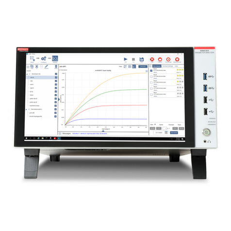
Linkam Scientific Instruments DSC450 User manual

DSC Dual Pan User Guide
Linkam Scientific Instruments
USER GUIDE
1.1.0

This page is intentionally blank

© 2017 Linkam Scientific Instruments
3
v1.1.0
Table of Contents
...................................................................................................................................................................4Introduction
...................................................................................................................................................................5Important Notices
.................................................................................................................................................................................................... 5Warranty
.................................................................................................................................................................................................... 5Technical Support
.................................................................................................................................................................................................... 5Equipment Maintenance
.................................................................................................................................................................................................... 5Handling Liquid Nitrogen
.................................................................................................................................................................................................... 5Feedback
...................................................................................................................................................................6Safety Precautions
.................................................................................................................................................................................................... 6Symbol Reference
...................................................................................................................................................................7System Overview
...................................................................................................................................................................8Stage Anatomy
...................................................................................................................................................................9Loading your sample into the stage
...................................................................................................................................................................10Mounting the stage onto a microscope
...................................................................................................................................................................11Connecting the liquid Nitrogen cooling
...................................................................................................................................................................12Controlling the DSC450in LINK
.................................................................................................................................................................................................... 12Main Control Screen
.................................................................................................................................................................................................... 12Sample Notes Screen
.................................................................................................................................................................................................... 12Sampling Screen
.................................................................................................................................................................................................... 13Data Collection
.................................................................................................................................................................................................... 13DSC Chart
.................................................................................................................................................................................................... 13Retrieving experiment information
.................................................................................................................................................................................................... 14Overlaying DSC Charts
.................................................................................................................................................................................................... 15Exporting Data (Excel)
.................................................................................................................................................................................................... 16Chart Cursor
.................................................................................................................................................................................................... 16Peak Measurement
.................................................................................................................................................................................................... 20Stage Calibration Adjustment
...................................................................................................................................................................21Connecting the ECP water pump

© 2017 Linkam Scientific Instruments
4
v1.1.0
Introduction
Thank you for purchasing your Linkam equipment, please take a moment to read this manual before settingup the equipment.
If you have purchased control software, please install the software first.
See your software manual for further installation instructions.

© 2017 Linkam Scientific Instruments
5
v1.1.0
Important Notices
Please register your products by going to www.linkam.co.ukand clicking on the activate warranty link. You will need to register your equipment with
us to:
Activate your warranty and technical support.
Access the online setup videos.
Warranty
This equipment has a warrantyagainst defects in material and workmanship for a period of12 months from the date ofshipping. Linkam will either
repair or replace products that prove to be defective. For warranty service or repair, this product must be returned to Linkam or a designated
service facility.
The warranty shall not apply to defects resultingfrom interfacing, unauthorized modification or misuse, operation outside ofthe environmental
specifications for the product, or improper site preparation or maintenance.
Technical Support
Any technical questions or queries should be addressed to the Technical Support Department at the address shown below and on the back of this
manual.
Tel: +44(0)1737 363 476
Email: support@linkam.co.uk
Equipment Maintenance
To clean the outside surfaces of the temperature control stages, use a small quantityofisopropyl alcohol with a soft cloth and gently wipe the
surface. To clean the sample chamber, use isopropyl alcohol (IPA) and cotton swabs. Take great care not to touch the temperature sensor
protruding from the side of the heatingelement. The sensor is very fragile.
Handling Liquid Nitrogen
To cool samples below room temperature an LNP95 liquid nitrogen pump system is required. Always use liquid nitrogen in a well ventilated room as
there is a danger ofasphyxiation.
Refer to your health and safety officer regardinginstructions on how to handle liquid nitrogen safely and ensure that you have the correct safety
equipment including gloves and safety goggles.
Feedback
Your feedback will be greatly appreciated, please email us directly info@linkam.co.uk

© 2017 Linkam Scientific Instruments
6
v1.1.0
Safety Precautions
1. Read this guide before using the equipment. Save these instructions for later use.
2. Follow all warnings and instructions which may be placed on the stage.
3. Never use the equipment if any cables have been damaged. Do not allow anyheavy objects to rest on the cables. Never lay the cables on the
floor.
4. Do not obstruct any ventilation holes. Do not attempt to insert anything into these openings. Provide adequate ventilation ofat least 75mm all
around the equipment.
5. Do not expose the equipment to water. Iffor any reason it gets wet then unplug it from the mains and contact Linkam Scientific Technical
Support.
6. The equipment is not intended to be used outdoors.
7. Ifanyproblems occur then turn all Linkam equipment offand contact Linkam Scientific Technical Support.
8. Do not remove any covers from the equipment, any servicingshould be carried out by qualified service personnel.
Symbol Reference
CAUTION :
·
Do not make orremove anyconnectionswhile the unit ispoweredon.
·
Do not remove the cover.
·
Servicingshouldonlybe done by qualified service personnel.
DANGER!
·
Surfaceswith this symbol may get veryhot.
·
Do not touch while in operation. Riskofsevere burnsor scalds.
·
Keep away fromflammable or combustable materials.

© 2017 Linkam Scientific Instruments
7
v1.1.0
System Overview
DSC450 Stage Specifications
·
Maximum temperature: 450°C
·
Minimum temperature: -170°C with LNP
·
Maximum heatingrate: 30°C/min
DCS450 System
The system consists ofa DSC450 stage, a T96 System Controller and optional LNP liquid nitrogen coolingpump.
LINK System control software and digital video capture can be added as an option to control from PC.
The DSC450 stage can be mounted onto most microscopes by using either specific stage clamps or an adapter plate.

© 2017 Linkam Scientific Instruments
8
v1.1.0
Stage Anatomy
1. DSC Sensor plate
2. Nitrogen outlet (connects to LNP)
3. Cooling water outlet
4. Stage Lid
5. DSC sensor cable
6. Stage lead cable
7. Lid locator pin
8. Cooling water inlet
9. Gas purge port
10. Liquid Nitrogen inlet (connects to Dewar)
11. Lid O Ringseal
12. Lid locator magnets
13. DSC reference pan position
14. DSC sample pan position
Accessories
·
Certified Indium Sample and Reference Pan pair.
·
22ø x 1mm Sapphire Furnace Lid
·
Stage clamps

© 2017 Linkam Scientific Instruments
9
v1.1.0
Loading your sample into the stage
1. Swivel the stage lid (4)to gain access to the DSCfurnace
2. Remove the furnace lid. This is a 22mmø x1mm sapphire window.
3. Place your reference crucible on the (13) sensor plate position labeled R.
4. Place your sample crucible on the (14)sensor plate position labeled S.
5. Replace the sapphire furnace lid.
6. Swingthe stage lid backinto position
7. Connect the ECP water pump, LNP and purge gas.

© 2017 Linkam Scientific Instruments
10
v1.1.0
Mounting the stage onto a microscope
The following description is for mountingthe stage on to microscopes which have a circular dovetail substage assembly
1. Attach the curved stage clamps to the baseplate ofthe stage usingthe supplied hex screws and the outer most holes in the base plate.
2. Adjust the two positioning screws so that approximately5mm ofthread is exposed on the inside edge ofthe clamp. This will roughlyposition
the stage in the centre ofthe dovetail.
3. Place the stage onto the dovetail, then focus an objective lens on the sample pan. Using the two positioningscrews, ensure that the sample
pan is in the field ofview and lock the stage in place by tighteningthe lockingthumbscrew.
Note: For other types of microscope substage, refer to the diagram included with the stage adapter.

© 2017 Linkam Scientific Instruments
11
v1.1.0
Connecting the liquid Nitrogen cooling
These connections need only be made ifthe experiments are to be carried out below room temperature.
The Dewar siphon is the thick white foam tubing and is attached to the liquid nitrogen Dewar. The thin blackcapillary tube inside the white foam
tube must be inserted into the liquid nitrogen cooling connectors on connector marked 'Dewar'
The white tubingslides on to the outside of the connector. Twist the siphon whilst slidingit on and push until it comes to a stop. It does not need to
go all the way to the base ofthe connector.
The thicker silicon tube from the LNP coolingpump ends in a white PTFEconnector, this is pushed over the end ofthe other stainless steel connector
marked 'LNP'as seen in the image.
The short tube branching from the side of this white connector is the Gas Purging Tube. There is a valve openingInsert connector inserted into the
end ofthis tube. Duringthe purgingprocedure, insert this connector into the Gas Purge Valve on the side of the stage to open it.
The Gas Purge Valve is opened when the Gas Insert is pushed firmlyinto the connector, a “click” is heard when the two parts are connected
properly. To remove the Gas Insert, push the outer sleeve ofGas Purge Valve toward the stage and the Gas Insert should drop out.
There is a second Gas Purge Valve on the opposite side ofthe stage to allow the gas to leave the stage. AGas Insert must also be inserted into this
Gas Purge Valve when purging.

© 2017 Linkam Scientific Instruments
12
v1.1.0
Controlling the DSC450in LINK
This section covers the LINK operations specific to the DSC Dual Pan stage. For instructions on usingthe basic functions ofLINK, such as setting up
temperature profiles and ramps, please see your LINK user guide, or the help section in the LINK software.
Main Control Screen
Main Control Screen
When the DSC450 stage is connected to LINK, the only additional information displayed is the Dsc power, in milliwatts.
Sample Notes Screen
Enter information about the data run on this tab. Please note: The sample description will also form part ofthe filename.
Sampling Screen

© 2017 Linkam Scientific Instruments
13
v1.1.0
The data samplingrate box allows you to set the data collection interval. The 50ms interval will provide the best resolution, but the maximum
recordingtime is 1 hour at this rate. Please set this to the appropriate value required for your experiment.
Data Collection
When a DSC stage is connected, LINKwill not record anydatafrom the start ramp in any profile, and will onlycollect data from the second ramp
onwards. This is to ensure that the temperatures on the DSC data run and overlays are synchronised.
DSC Chart
By default, two charts are displayed on the screen; (1) DSC power, images and temperature plotted against time, and (2) DSC power against
temperature.
The ratios of these charts can be adjusted usingthe "Chart Split"setting. Set this to 0% to see only the DSC vTemperature chart or 100% for solely
the Time chart. Please note that some features and traces ,such as the cursor tool, Peak measurement feature or image traces, are only available
within the Time chart.
Retrieving experiment information
Additional information about an experiment (such as the "Sample Notes"or the Microscope and Objective used) can be retrieved usingthe
following procedure:
1. Right Clickon the Chart and select "Toolbox"
2. Click on the "About" Tab.

© 2017 Linkam Scientific Instruments
14
v1.1.0
Overlaying DSC Charts
Upto three DSC traces may be overlaid within a single graph. This feature is particularly useful for comparing plots where the same temperature
profile was used.
This can be done using the following procedure:
1. Open a DSC data file by selecting Open Data File from the FIle menu.
2. Apopup window will appear. Click "Yes", and select the second data file.
3. Repeat step 2 to overlay a third trace, otherwise, Click "No"

© 2017 Linkam Scientific Instruments
15
v1.1.0
You will now see a chart with all three traces visible.
Exporting Data (Excel)
DSC data can be exported as a tab delimited txt file. This format is compatible with Excel.
To do this, right click on the Chart and select "Export".
Set the "Save as type"to "Text files (*.txt)". This file can now be opened in Excel from the "Open With" menu option.

© 2017 Linkam Scientific Instruments
16
v1.1.0
Chart Cursor
The chart cursor is only available in the Time chart.
Peak Measurement
Peaks, which indicate transition phases on the DSC data chart can be measured using the following procedure.
Right click on the data chart and select 'DSC Toolbox'
Select the 'Peak measurement' tab and the below window will appear. Click on the the measure button for the peak you wish to measure. Up to 5
peaks can be measured on any one data chart.

© 2017 Linkam Scientific Instruments
17
v1.1.0
Manual Measure
Click the "Measure" button next to the Peak you would like to measure. Ifyou would like to correct a measurement, click the "Clear"button first.
Acursor will now appear on the time data chart for you to select the base line start point. This will the be point where you want your base line to be
taken from and can be just before the line starts to dip toward the peak.
Left click to select the base line start point, and the system will ask you to select the base line end point, which is usually the point just after the
peak line flattens out.
Left click to finalise the selection and the system will next ask you to select the extrapolation line start point. The extrapolation line is a tangent to
the peak that is extrapolated so that it intersects with the hypothetical baseline.The start of the extrapolation line is the point at which the peak
line is at it’s steepest.

© 2017 Linkam Scientific Instruments
18
v1.1.0
Left click to finalise the selection and the system will request the extrapolation line end point. This is a point further down the peak line that
enables the software to make an extrapolation to the baseline.
Left click to finalise the peak measurement and the chart will update. The peak measurements are added at the top of the graph under the file
name.

© 2017 Linkam Scientific Instruments
19
v1.1.0
The appearance ofthe peak measurement can be altered by selectingthe 'Peakoptions'tab:
Uncheckingthe 'Lines'box will remove the black lines showingthe base and extrapolation lines from the chart. This defaults to on when a peak is
measured.
Checkingthe 'Fill'box will fill the peak area with solid colour to make it more visible. This defaults to offwhen a peak is measured.

© 2017 Linkam Scientific Instruments
20
v1.1.0
Stage Calibration Adjustment
The stage calibration may occasionally need to be adjusted (for example: a different type ofcrucible pan is used).
To do this, first run an Indium sample on the DSC and measure the peak transition energy.
Then clickon the settings gear icon and clickon the "DSC Indium calibration Values" button.
Enter the Indium sample mass and measured transition enthalpy. Then clickapply.
The stage may also need to be adjusted for temperature accuracy.
To set this, click on the settings gear icon and then clickon the "Change sample calibration Values"button.
Follow the instructions presented on the screen.
When you are done, click on the red cross in the corner and tick the "Apply sample calibration"tickbox.
Please refer to the "Sample Calibration"section ofthe LINK manual for further information on this.
Table of contents

