Linx Technologies HumPRC Series Instruction Manual

HumPRCTM Series 868MHz
RF Transceiver Module
Data Guide

Table of Contents
1 Description
1 Features
2 Ordering Information
2 Absolute Maximum Ratings
3 Electrical Specications
5 Typical Performance Graphs
10 Pin Assignments
11 Pin Descriptions
13 Module Dimensions
14 Theory of Operation
15 Module Description
16 Transceiver Operation
17 Transmit Operation
17 Receive Operation
18 System Operation
20 Polite Spectrum Access
21 ETSI Compliance
22 Addressing Modes
23 Reading the Transmitter Address
23 Restore Factory Defaults
24 AES Encryption
25 The Join Process
28 Operation with the HumPROTM Series
29 Carrier Sense Multiple Access (CSMA)
30 Acknowledgement
30 External Amplier Control
31 Conguring the Status Lines
31 Using the LATCH_EN Line
32 Using the MODE_IND Line
Warning: Some customers may want Linx radio frequency (“RF”)
products to control machinery or devices remotely, including machinery
or devices that can cause death, bodily injuries, and/or property
damage if improperly or inadvertently triggered, particularly in industrial
settings or other applications implicating life-safety concerns (“Life and
Property Safety Situations”).
NO OEM LINX REMOTE CONTROL OR FUNCTION MODULE
SHOULD EVER BE USED IN LIFE AND PROPERTY SAFETY
SITUATIONS. No OEM Linx Remote Control or Function Module
should be modified for Life and Property Safety Situations. Such
modification cannot provide sufficient safety and will void the product’s
regulatory certification and warranty.
Customers may use our (non-Function) Modules, Antenna and
Connectors as part of other systems in Life Safety Situations, but
only with necessary and industry appropriate redundancies and
in compliance with applicable safety standards, including without
limitation, ANSI and NFPA standards. It is solely the responsibility of any
Linx customer who uses one or more of these products to incorporate
appropriate redundancies and safety standards for the Life and
Property Safety Situation application.
Do not use this or any Linx product to trigger an action directly
from the data line or RSSI lines without a protocol or encoder/
decoder to validate the data. Without validation, any signal from
another unrelated transmitter in the environment received by the module
could inadvertently trigger the action.
All RF products are susceptible to RF interference that can prevent
communication. RF products without frequency agility or hopping
implemented are more subject to interference. This module does have
a frequency hopping protocol built in, but the developer should still be
aware of the risk of interference.
Do not use any Linx product over the limits in this data guide.
Excessive voltage or extended operation at the maximum voltage could
cause product failure. Exceeding the reflow temperature profile could
cause product failure which is not immediately evident.
Do not make any physical or electrical modifications to any Linx
product. This will void the warranty and regulatory and UL certifications
and may cause product failure which is not immediately evident.
!

– –
1
Description
The HumPRCTM Series is the most complete
system to integrate bi-directional remote
control into many different applications. No
programming is required, and both module
and finished hardware options are available,
making it the easiest solution to implement.
The module provides long-range transmission
at 868MHz utilizing Listen Before Talk and
Adaptive Frequency Agility and industry-standard encryption for secure
and robust communications. The HumPRCTM Series interoperates with
the HumPROTM family, making it the only remote control solution that
simultaneously supports data applications for seamless integration with
sensor and control IoT applications.
Eight status lines can be set up in any combination of inputs and outputs
for the transfer of button or contact states. A selectable acknowledgement
indicates that the transmission was successfully received.
Primary settings are hardware-selectable, which eliminates the need for an
external microcontroller or other digital interface. For advanced features,
optional software configuration is provided by a UART interface.
Housed in a compact reflow-compatible SMD package, the transceiver
requires no external RF components except an antenna, which greatly
simplifies integration and lowers assembly costs.
Features
• Add bi-directional remote control
capabilities to any product
• Pre-compiled software
• No programming required
• 128-bit AES encryption
• 8 status lines
• Polite Spectrum Access (PSA)
• Selectable acknowledgements
• CE compliant/ RED compliant
• Fully interoperable with all
HumPROTM Series devices &
gateways
HumPRCTM Series 868MHz
RF Transceiver Module
Data Guide
Figure 1: Packages
Revised 9/27/2017
33 Using the PB Line
34 Using the Low Power Features
36 The Command Data Interface
37 Reading from Registers
38 Writing to Registers
39 Command Length Optimization
40 Example Code for Encoding Read/Write Commands
42 The Command Data Interface Command Set
80 Typical Applications
84 HumPRCTM Series Long-Range Handheld Transmitter
86 Power Supply Requirements
86 Antenna Considerations
87 Interference Considerations
88 Pad Layout
89 Microstrip Details
90 Board Layout Guidelines
91 Helpful Application Notes from Linx
92 Production Guidelines
92 Hand Assembly
92 Automated Assembly
94 General Antenna Rules
96 Common Antenna Styles
98 Regulatory Considerations
101 OEM Labeling Requirements
102 Notes

– – – –
2 3
HumPRCTM Series Transceiver Specifications
Parameter Symbol Min. Typ. Max. Units Notes
Power Supply
Operating Voltage VCC 2.0 3.6 VDC
TX Supply Current lCCTX
at +10dBm 40.5 41.5 mA 1,2
at 0dBm 22 24 mA 1,2
RX Supply Current lCCRX 23.5 24.5 mA 1,2,3
Power-Down Current lPDN 0.7 1.4 µA 1,2
RF Section
Operating Frequency Band FC863 870 MHz
Number of hop channels 70
Channel spacing 100 kHz
20 dB OBW 48 kHz
Receiver BW 102 kHz
FSK deviation ± 14 kHz
Scan time / channel (avg) 0.91 ms
Channel Lock time 76 ms
RF Data Rate 38.4 kbps
Modulation GFSK
Data Encoding 6/7 RLL
Number of Hop Sequences 6
Receiver Section
Spurious Emissions –47 dBm
IF Frequency 330.078 kHz
Receiver Sensitivity –97 –100 dBm 5
RSSI Dynamic Range 85 dB
Transmitter Section
Max Output Power PO+8.5 +10.6 dBm 6,15
Harmonic Emissions PH–41 dBc 6
Output Power Range –5 9 dB 6
Antenna Port
RF Impedance RIN 50 Ω4
Environmental
Operating Temp. Range −40 +85 ºC 4
Electrical SpecicationsOrdering Information
Figure 2: Ordering Information
Warning: This product incorporates numerous static-sensitive
components. Always wear an ESD wrist strap and observe proper ESD
handling procedures when working with this device. Failure to observe
this precaution may result in module damage or failure.
Absolute Maximum Ratings
Supply Voltage Vcc −0.3 to +3.9 VDC
Any Input or Output Pin −0.3 to VCC + 0.3 VDC
RF Input 0 dBm
Operating Temperature −40 to +85 ºC
Storage Temperature −40 to +85 ºC
Exceeding any of the limits of this section may lead to permanent damage to the device.
Furthermore, extended operation at these maximum ratings may reduce the life of this
device.
Absolute Maximum Ratings
Figure 3: Absolute Maximum Ratings
Ordering Information
Part Number Description
HUM-868-PRC 868MHz HumPRCTM Series Remote Control Transceiver,
Castellation Interface, External Antenna Connection
HUM-868-PRC-CAS 868MHz HumPRCTM Series Remote Control Transceiver,
Certified, Castellation Interface, External Antenna Connection
HUM-868-PRC-UFL 868MHz HumPRCTM Series Remote Control Transceiver,
Certified, Castellation Interface, U.FL Connector
EVM-868-PRC-CAS 868MHz HumPRCTM Series Carrier Board, Through-Hole Pin
Interface, RP-SMA Connector
EVM-868-PRC-UFL 868MHz HumPRCTM Series Carrier Board, Through-Hole Pin
Interface, U.FL Connector
MDEV-868-PRC 868MHz HumPRCTM Series Master Development System

– – – –
4 5
HumPRCTM Series Transceiver Specifications
Parameter Symbol Min. Typ. Max. Units Notes
Timing
Module Turn-On Time
Via VCC 71 190 ms 4
Via POWER_DOWN 35 ms 4
Via Standby 4.12 ms 4
Serial Command Response
Volatile R/W 0.4 5 ms 8
NV Update 2.4 50 ms 8
Factory Reset 199 484 ms 14
Channel Dwell Time 400 ms
Interface Section
UART Data rate 9,600 115,200 bps
Input
Logic Low VIL 0.3*VCC VDC
Logic High VIH 0.7*VCC VDC
Output
Logic Low, MODE_IND,
ACK_OUT VOLM 0.3*VCC VDC 1,9
Logic High, MODE_IND,
ACK_OUT VOHM 0.7*VCC VDC 1,9
Logic Low VOL 0.3*VCC 1,10
Logic High VOH 0.7*VCC 1,10
Flash (Non-Volatile) Memory Specifications
Flash Refresh Cycles 2,000 cycles 12
1. Measured at 3.3V VCC
2. Measured at 25ºC
3. Input power < -60dBm
4. Characterized but not tested
5. PER = 5%
6. Into a 50-ohm load
7. No RF interference
8. From end of command to start of
response
9. 60mA source/sink
10. 6mA source/sink
11. End of CMD_DATA_OUT stop bit to
change in CRESP
12. Number of non-volatile memory refresh
cycles. The number of write operations
per refresh cycle varies from 8 to 150.
13. With CSMA disabled
14. Start of factory reset command to end
of last ACK response
15. The maximum output power is limited
on the higher channels in order to
comply with ETSI regulations.
Figure 4: Electrical Specifications
Typical Performance Graphs
Figure 5: HumPRCTM Series Transceiver Max Output Power vs. Supply Voltage
8.5
9.0
9.5
10.0
10.5
11.0
2.0 2.5 3.3 3.6
TX Output Power (dBm)
Supply Voltage (V)
85°C
25°C
-40°C
15
20
25
30
35
40
-5
059
Supply Current (mA)
TX Output Power (dBm)
85°C
25°C
-40°C
Figure 6: HumPRCTM Series Transceiver Average Current vs. Transmitter Output Power at 2.5V

– – – –
6 7
20
22
24
26
28
30
32
34
36
38
40
-5
059
Supply Current (mA)
TX Output Power (dBm)
85°C
25°C
-40°C
Figure 8: HumPRCTM Series Transceiver Average TX Current vs. Transmitter Output Power at 3.3V
36.50
37.00
37.50
38.00
38.50
39.00
39.50
40.00
2V 2.5V 3.3V
3.6V
Supply Current (mA)
Supply Voltage (V)
85°C
25°C
-40°C
Figure 7: HumPRCTM Series Transceiver TX Current vs. Supply Voltage at Max Power
22.00
22.20
22.40
22.60
22.80
23.00
23.20
23.40
2V 2.5V 3.3V 3.6V
Supply Current (mA)
Supply Voltage (V)
85°C
25°C
-40°C
Figure 9: HumPRCTM Series Transceiver TX Current vs. Supply Voltage at 0dBm
22.5
22.7
22.9
23.1
23.3
23.5
23.7
23.9
24.1
24.3
24.5
2 2.1 2.2 2.3 2.4 2.5 2.6 2.7 2.8 2.9 3 3.1 3.2 3.3 3.4 3.5 3.6
Supply Current (mA)
Supply Voltage (V)
85°C
25°C
-40°C
Figure 10: HumPRCTM Series Transceiver RX Scan Current vs. Supply Voltage, 38.8kbps
Current consumption while the module is scanning for a transmission. The current is
approximately 0.5mA higher when receiving data at 38.8kbps.

– – – –
8 9
0.00
0.20
0.40
0.60
0.80
1.00
1.20
1.40
2.5 3.3 3.6
Standby Current (µA)
Supply Voltage (V)
-40°C
25°C
85°C
Figure 11: HumPRCTM Series Transceiver Standby Current Consumption vs. Supply Voltage
-105.00
-95.00
-85.00
-75.00
-65.00
-55.00
-45.00
-35.00
-25.00
-15.00
-100.00 -90.00 -80.00 -70.00 -60.00 -50.00 -40.00 -30.00 -20.00 -10.00
0.00
RSSI Reading (dBm)
Input Power (dBm)
-40°C 25°C
85°C
Figure 12: HumPRCTM Series Transceiver RSSI Voltage vs. Input Power

– – – –
10 11
Pin Assignments
There are three version of the module. The standard version is the smallest.
The other versions have mostly the same pin assignments, but the antenna
is routed to either a castellation (-CAS) or a U.FL connector (-UFL),
depending on the part number ordered.
Figure 14: HumPRCTM Series Transceiver Standard Version Pin Assignments (Top View)
Pin Descriptions
Pin Number Name I/O Description
1, 2, 3, 4, 5,
6, 7, 8 S0–S71I/O
Status Lines. Each line can be configured
as either an input to register button or
contact closures or as an output to control
application circuitry.
9, 14, 15, 16,
17, 18, 20,
25, 32
GND — Ground
10 C0 I
This line sets the input/output direction for
status lines S0-S3. When low, the lines are
outputs; when high they are inputs. Do not
leave floating.
11 C1 I
This line sets the input/output direction for
status lines S4-S7. When low, the lines are
outputs; when high they are inputs. Do not
leave floating.
12 POWER_DOWN I
Power Down. Pulling this line low places the
module into a low-power state. The module
is not functional in this state. Pull high for
normal operation. Do not leave floating.
Pin Descriptions
30
31
32
1
2
3
4
20
19
18
17
16
15
14
56789 10 11 12 13
29 28 27 26 25 24 23 22 21
ANT
GND
GND
GND
GND
GND
GND
ACK_OUT
MODE_IND
GND
S7
S4
S5
S6
S2
S3
S1
S0
C1
C0
GND
LATCH_EN
POWER_DOWN
ACK_EN
PB
CMD_DATA_IN
CMD_DATA_OUT
LNA_EN
PA_EN
GND
VCC
RESET
30
31
32
1
2
3
4
19 18
56789 10 11 12 13
29 28 27 26 25 24 23 22 21
NC
GND
ACK_OUT
MODE_IND
GND
S7
S4
S5
S6
S2
S3
S1
S0
C1
C0
GND
LATCH_EN
POWER_DOWN
ACK_EN
PB
CMD_DATA_IN
CMD_DATA_OUT
LNA_EN
PA_EN
GND
VCC
RESET
ANT
Figure 13: HumPRCTM Series Transceiver Encapsulated Version Pin Assignments - Castellation Connection (Top View)
30
31
32
1
2
3
4
19 18
56789 10 11 12 13
29 28 27 26 25 24 23 22 21
ANT
GND
ACK_OUT
MODE_IND
GND
S7
S4
S5
S6
S2
S3
S1
S0
C1
C0
GND
LATCH_EN
POWER_DOWN
ACK_EN
PB
CMD_DATA_IN
CMD_DATA_OUT
LNA_EN
PA_EN
GND
VCC
RESET
NC
Figure 15: HumPRCTM Series Transceiver Encapsulated Version Pin Assignments - UFL Connection (Top View)

– – – –
12 13
0.45"
(11.43)
0.812"
(20.62)
0.116"
(2.95)
0.271"
(6.88)
0.195"
(4.96)
0.078"
(1.98)
Module Dimensions
Figure 17: HumPRCTM Series Transceiver Dimensions
0.45"
(11.43)
0.55"
(13.97)
0.07"
(1.78)
Figure 18: HumPRCTM Series Transceiver Encapsulated Version Dimensions
Pin Descriptions
Pin Number Name I/O Description
13 LATCH_EN I
If this line is high, then the status line
outputs are latched (a received command
to activate a status line toggles the output
state). If this line is low, then the output lines
are momentary (active for as long as a valid
signal is received). Do not leave floating.
19 ANTENNA — 50-ohm RF Antenna Port
21 VCC — Supply Voltage
22 RESET2I
This line resets the module when pulled
low. It should be pulled high for normal
operation. Leave unconnected to minimize
leakage current.
23 LNA_EN 0
Low Noise Amplifier Enable. This line is
driven high when receiving. It is intended to
activate an optional external LNA.
24 PA_EN O
Power Amplifier Enable. This line is driven
high when transmitting. It is intended to
activate an optional external power amplifier.
26 CMD_DATA_OUT O Command Data Out. Output line for the
serial interface commands
27 CMD_DATA_IN I
Command Data In. Input line for the serial
interface commands. If serial control is not
used, this line should be tied to supply to
minimize current consumption.
28 ACK_EN I
Pull this line high to enable the module to
send an acknowledgement message after
a valid control message has been received.
Do not leave floating.
29 PB1I
A high on this line initiates the Join Process,
which causes two units to accept each
other’s transmissions. It is also used with
a special sequence to reset the module to
factory default configuration.
30 MODE_IND O
This line indicates module activity. It can
source enough current to drive a small
LED, causing it to flash. The duration of the
flashes indicates the module’s current state.
31 ACK_OUT O
This line goes high when the module
receives an acknowledgement message
from another module after sending a control
message.
1. These lines have an internal 20kΩpull-down resistor
2. These lines have an internal 10kΩpull-up resistor
Figure 16: HumPRCTM Series Transceiver Pin Descriptions
– – – –
14 15
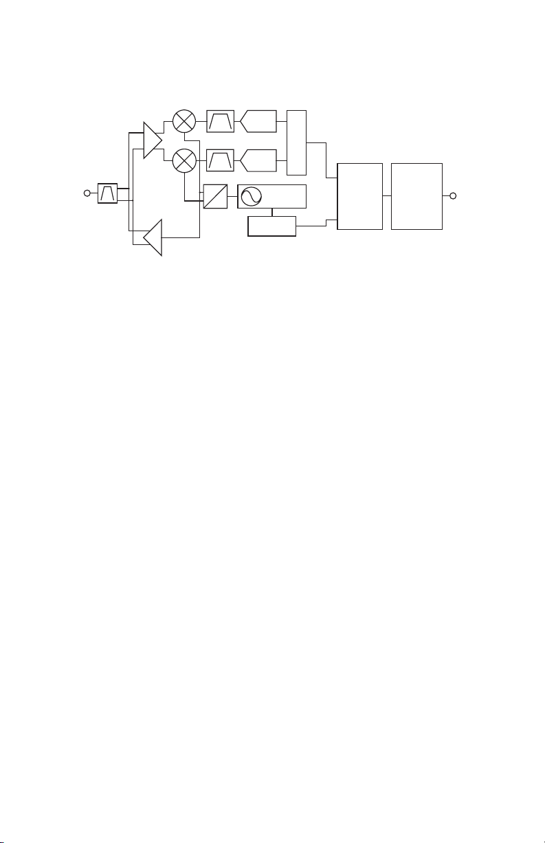
Theory of Operation
The HumPRCTM Series transceiver is a low-cost, high-performance
synthesized FSK transceiver. Figure 19 shows the module’s block diagram.
The HumPRCTM Series transceiver operates in the 863 to 870MHz
frequency band. The transmitter output power is programmable, though
the maximum power is automatically limited on the higher channels to
comply with ETSI regulations. The range varies depending on the antenna
implementation and the local RF environment. When operating near the
maximum range, there can be higher packet loss when transmitting on the
higher channels due to output power limiting, although it is anticipated that
most customers won’t notice any difference since the transceiver utilizes 70
channels for transmissions.
The RF carrier is generated directly by a frequency synthesizer that includes
an on-chip VCO. The received RF signal is amplified by a low noise
amplifier (LNA) and down-converted to I/Q quadrature signals. The I/Q
signals are digitized by ADCs.
A low-power onboard communications processor performs the radio
control and management functions including Automatic Gain Control
(AGC), filtering, demodulation and packet synchronization. A control
processor performs the higher level functions and controls the serial and
hardware interfaces.
A crystal oscillator generates the reference frequency for the synthesizer
and clocks for the ADCs and the processor.
Figure 19: HumPRCTM Series Transceiver RF Section Block Diagram
PA
LNA
0
90
FREQ
SYNTH
ADC
ADC
DEMODULATOR
MODULATOR
ANTENNA PROCESSORGPIO /
INTERFACE
INTERFACE
Module Description
The HumPRCTM Series remote control transceiver module is a completely
integrated RF transceiver and processor that is designed to send the
logic state of its inputs to a remote unit and replicate the logic states of
the remote unit’s inputs. This allows for the easy creation of basic remote
control systems.
The module operates through a series of dedicated I/O lines, resulting in
a hardware design that does not need any software development. The
module does have a serial interface that allows for some configuration in
applications that need specific control. This interface is likely not needed for
basic remote control applications.
Since this module can act as both transmitter and receiver, terminology and
descriptions are important. This guide uses the term Initiating Unit (IU) to
describe a module that is transmitting commands. Responding Unit (RU) is
used to describe a module that is receiving commands.
The module has 8 status lines numbered S0 through S7. These can be set
as inputs for buttons or contacts or as outputs to drive application circuitry.
When S0 is taken high on the IU, S0 goes high on the RU, and so forth. A
line that is an input on one side needs to be set as an output on the other
side.
The HumPRCTM Series adds a remote control application layer to the
protocol stack used by the HumPROTM Series data modem. This enables
the simple creation of remote control systems that benefit from the robust
feature set of the protocol stack, such as a fast locking Listen Before Talk
and Adaptive Frequency Agility (LBT+AFA) algorithm, AES128 encryption,
32-bit addressing, assured delivery and a simple Join Process for
associating multiple modules with each other.
As a result, much of the HumPRCTM Series terminology is the same as the
HumPROTM Series. Likewise, most of the software registers are the same,
though some do not apply to the remote control application.
A result of this common protocol stack is that HumPRCTM Series
transmissions can be received by another HumPRCTM Series module for
simple remote control applications or by a HumPROTM Series module for
applications that want to combine data transmissions (such as sensor
values) with remote control functionality.

– – – –
16 17
Transceiver Operation
The transceiver has two roles: Initiating Unit (IU) that transmits control
messages and Responding Unit (RU) that receives control messages. If all
of the status lines are set as inputs, then the module is set as an IU only.
The module stays in a low power sleep mode until a status line goes high,
starting the Transmit Operation.
If all of the status lines are set as outputs, then the module is set as an RU
only. It stays in Receive Operation looking for a valid transmission from a
paired IU.
A module with both input and output status lines can operate as an IU
and an RU. The module idles in Receive Operation until either a valid
transmission is received or a status line input goes high, initiating the
Transmit operation.
When an input goes high, the transceiver captures the logic state of each
of the status lines. The line states are placed into a packet and transmitted
using the configured addressing mode, hop sequence and encryption key
(if enabled).
An associated RU receives the packet and sets its status line outputs
according to the received packet. It then stays synchronized with the IU
and updates the states of its outputs with every packet. Its outputs can be
connected to external circuitry that activates when the lines go high.
The RU can also send an acknowledgement back to the IU. If the ACK_EN
line is high when a valid control packet is received, the RU sends back an
acknowledgement. When the IU receives the acknowledgement, it raises its
ACK_OUT line. The ACK_EN line can be connected to ground to disable
acknowledgements, connected to the power supply to acknowledge
on receipt of the valid command or controlled by external circuitry to
acknowledge when an action has taken place.
The ACK_EN can be connected to an LED as an indication to the user or
used by the system in other ways, such as updating a display or being
used to deactivate an automated system.
Transmit Operation
When a status line input goes high, the module enters the Initiating Unit
role. In this role, the module captures the logic states of the status line
inputs and automatically creates a REMOTE_ACTIVATE packet. The packet
is transmitted every 140ms nominally (240ms max) for as long as a status
line input is held high. After each transmission, the module listens for a
REMOTE_CONFIRM reply from the RU. This continues for as long as any
status line input is high.
The REMOTE_CONFIRM packet contains two values. One indicates how
long the ACK_OUT line should go high on the IU (20ms by default) and the
other indicates if the IU should stay awake after the status line inputs go
low (go to sleep by default). The module activates the ACK_OUT line for as
long as instructed and loops back to check the status line inputs and send
another REMOTE_ACTIVATE packet.
When all status line inputs go low, the module transmits two REMOTE_
ACTIVATE packets indicating that all lines are low. If all status lines are
inputs, it then goes to sleep after 760ms unless a REMOTE_CONFIRM
packet is received instructing the IU to stay awake longer.
Receive Operation
When the module is awake and not in transmit operation, it is in receive
operation listening for valid packets. When a REMOTE_ACTIVATE packet
is received, the module enters the Responding Unit role and processes the
received status line states. It remains in the RU mode until 760ms elapses
without an incoming REMOTE_ACTIVATE message.
Unlatched status line outputs are set to match the corresponding bit state
in the received packet.
For latched outputs, the line changes state (off ªon or on ªoff) whenever
the corresponding bit changes from 0 to 1. All other combinations of
the new and old status bit do not change the status line. This normally
changes the output state every time that the associated transmitter input
changes from 0 to 1.
If the ACK_EN line is high when a valid message is received, a REMOTE_
CONFIRM message is transmitted to the IU with values to set the ACK_
OUT high for 20ms and go to sleep after the default 760ms. These values
cannot be changed in the HumPRCTM Series, but a packet with different
values can be generated using the HumPROTM Series and a microcontroller.
– – – –
18 19
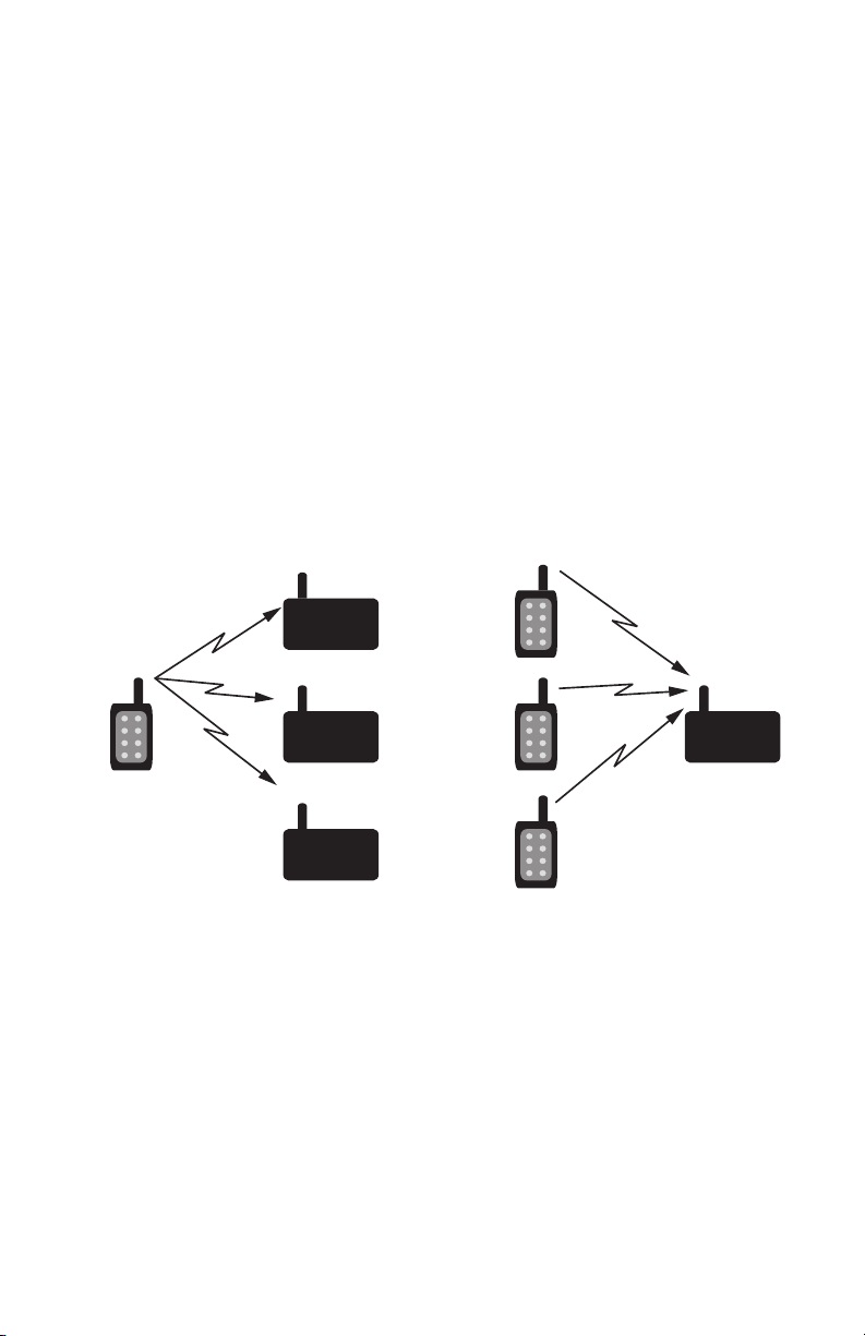
System Operation
Transmitters and receivers are paired using the built-in Join Process (see
the Join Process for details). One device is configured as an Administrator
and creates the network address and encryption key. When Nodes join,
the Administrator sends them the encryption key, network address and
their unique address within the network. The addressing method used by
the HumPRCTM Series modules can support up to hundreds of nodes,
depending on the use model (duration of activations and how often they
are sent).
It is up to the designer to determine which device makes the most sense
as the Administrator in the final system, but there are some common
configurations. In a system with one transmitter and one receiver, it does
not matter which is the Administrator. In a system where one transmitter
is going to activate several receivers, the transmitter is normally the
Administrator (Figure 20 a). In a system with one receiver and multiple
transmitters, the receiver should be the Administrator (Figure 20 b).
A system with multiple transmitters and receivers can use any of the
devices as an Administrator (Figure 21 a) or may use a separate device
that is only used to join new devices to the network (Figure 21 b). Once all
system nodes have received the key and their address, the Administrator
node operates the same as any other node.
By default, the Administrator and all Nodes broadcast to the entire network.
All transmitters can activate all receivers in the network. An external
microcontroller can be used to change the UDESTID0 register to activate
a specific Node in the network. This is a more advanced operation and
requires the microcontroller and custom firmware.
Administrator
Administrator
Figure 20: HumPRCTM Series Transceiver Transmitter to Receiver Ratios
a b
Administrator
Figure 21: HumPRCTM Series Transceiver Multiple TX and RX
a b

– – – –
20 21
Polite Spectrum Access
Europe’s ETSI standards have very specific requirements for operating in
the 868MHz band, which are contained in EN 300 220-1. One of the items
is called Polite Spectrum Access (PSA) and is a method of performing a
Clear Channel Assessment before transmitting to mitigate interference with
other systems.
The HUM-868-PRO employs Polite Spectrum Access. This allows the
module to exceed the 0.01% duty cycle limitation that otherwise applies
to modules operating in the 863-870MHz band. This is advantageous for
systems that need to transmit large data streams or have an unpredictable
usage pattern.
Systems that employ Polite Spectrum Access, while exempt from the
normal duty cycle restrictions, must meet channel occupancy time
requirements in ETSI EN 300 220-1 v3.1.1 section 5.21.3. The HUM-868
PRO module has a built-in mechanism that ensures compliance to this
requirement by internally limiting each channel’s cumulative on time. This
limits the transmission time on any given channel to 33.3 seconds per hour.
The module uses 70 channels so it can transmit for 2,333s of every hour or
about 64% assuming no delay for transmissions by other units.
It is preferable to spread the transmit time out evenly to avoid using all of
the time at the start of the hour and then having 21 minutes’ delay at the
end of the hour. To accomplish this, the module divides the time into blocks
of 180s called bandspread intervals. The module can transmit on each
channel for 1.66s of every 180s (33.3s of every 3600s ÷ 20).
The PSA options are configured with the ENCSMA register. Setting the
register to 0x00 disables PSA and the transmission is immediate. This can
be used in applications with an inherent duty cycle <0.1%.
Setting the register to 0x01 enables LBT but without the transmitter on time
duty cycle restriction.
Setting the register to 0x02 enables the full LBT with transmitter on time
restriction. This complies with the ETSI regulations for LBT + AFA.
Leaving the register in its default value of 0x02 enables Polite Spectrum
Access. To maintain validity of the HUM-868-PRO module Declaration of
Conformity (DoC) this setting (0x02) must be used and must not be user
adjustable.
ETSI Compliance
The HumPRC™ Series module has been tested and conforms to
requirements of the current Radio Equipment Directive (RED) standards.
The module’s test report and Declaration of Conformity (DoC) are available
from Linx Technologies upon request. Linx Technologies Reference Guide
RG-00111 outlines the test setup and radio configurations that were used
in the testing and certification of this device.
Designs that incorporate the module as it was tested in RG-00111 may
utilize portions of our test data in their application. For those designs that
differ, please contact Linx Technologies for certification assistance and
advice.
Note: The integrator is solely responsible for ensuring that the final
product complies with CE / ETSI requirements. This includes all testing
and any application specific requirements.

– – – –
22 23
Addressing Modes
The module has very flexible addressing methods selected with the
ADDMODE register. It can be changed during operation. The transmitting
module addresses packets according to the addressing mode
configuration. The receiving module processes all addressing types
regardless of the ADDMODE configuration. If the received message
matches the addressing criteria, it is output on the UART. Otherwise it is
discarded. The ADDMODE configuration also enables assured delivery.
There are three addressing modes: DSN, User and Extended User. Each
mode offers different communications methods, but all use source and
destination addressing. The source address is for the transmitting unit,
the destination address is the intended receiver. Each mode uses different
registers for both the source and destination addresses.
Extended User Addressing mode uses the four user destination address
bytes (UDESTID[3-0]) as a destination address. The module’s local address
is contained in the four user source ID registers (USRCID[3-0]).
In normal operation, each module has a user ID mask (UMASK[3-0]) that
splits the 32 address bits into up to three fields to provide a network
address and address fields for sub-networks, supporting both individual
addressing and broadcast addressing within the user’s network.
The HumPRCTM Series is normally configured using the Join Process,
which sets the addressing mode to Extended User mode. The other modes
would normally only be used if the HumPRCTM Series is being implemented
in a mixed system that also uses the HumPROTM Series modules.
Please see the HumPROTM Series data guide for a description of the
other addressing modes. A detailed explanation and examples for each
addressing mode are given in Reference Guide RG-00105.
Reading the Transmitter Address
The HumPRCTM Series modules do not require any software for basic
operation. There is no compiler to get, no code to write and download into
the module. However, the built-in Command Data Interface (CDI) can be
used to add additional or advanced functionality to a system.
One such feature is the ability to read out of the receiver the identity of the
transmitter that sent the commands. This allows an external processor to
log access attempts or set additional controls over which transmitters are
allowed to activate the product outside of the module.
By default, the module automatically configures itself to respond to the
transmitting module (AUTOADDR = 0x07). This configuration takes the
source address from the received packet and writes it to the UDESTID
registers UDESTID[0-3]. Reading these registers after a valid transmission
has been received indicates the transmitter that sent the command.
Restore Factory Defaults
The transceiver is reset to factory default by taking the PB line high briefly
4 times, then holding PB high for more than 3 seconds. Each brief interval
must be high 0.1 to 2 seconds and low 0.1 to 2 seconds. (1 second
nominal high / low cycle). The sequence helps prevent accidental resets.
Once the sequence is recognized, the MODE_IND line blinks in groups
of three until the PB line goes low. After PB goes low, the non-volatile
configurations are set to the factory default values and the module is
restarted. The default UART data rate is 9,600bps.
If the timing on PB does not match the limits, the sequence is ignored.
Another attempt can be made after lowering PB for at least 3 seconds.

– – – –
24 25
The Join Process
The Join Process is a method of generating a random encryption key and
random network base address, then distributing the key and addresses to
associated modules through a series of button presses. This makes it very
simple to establish an encrypted network in the field or add new nodes to
an existing network without any additional equipment. It is also possible
to trigger the Join Process through commands on the Command Data
Interface.
All modules configured from the same administrator using the Join Process
can communicate with each other. Other modules are added to the
network one at a time.
The hardware required is a pushbutton that is connected to the PB
line. This takes the line to VCC when it is pressed and ground when it
is released. An LED connected to the MODE_IND line provides visual
indication of the module’s state.
A module is set as an administrator by pressing and holding the button for
30 seconds to start the Generate Key function. While the button is held,
the MODE_IND line is on. After 30s, the MODE_IND line repeats a double
blink, indicating that the function is selected. When the button is released
the key and address generation are performed and the module becomes
an administrator.
When Generate Key is performed, the unit is set as the network
administrator. It generates a random 128-bit AES encryption key based on
ambient RF noise and scrambled by an encryption operation. If UMASK
is the default value (0xFFFFFFFF), it is set to 0x000000FF, supporting
up to 254 nodes, and ADDMODE is set to Extended User Address
with encryption (0x27) (or without encryption (0x07) if flag PGKEY in
the SECOPT register was set to 0 by serial command). UMASK and
ADDMODE are not changed if UMASK is not 0xFFFFFFFF. A random
32-bit address is generated. By default, the lower 8 bits are 0, forming the
network base address. Other nodes are assigned sequential addresses,
starting with network base address +1. UDESTID is set to the bitwise OR
of USRCID and UMASK, which is the network broadcast address.
AES Encryption
HumPRCTM Series modules offer AES encryption. Encryption algorithms are
complex mathematical calculations that use a large number called a key
to scramble data before transmission. This is done so that unauthorized
persons who may intercept the signal cannot access the data. To decrypt
the data, the receiver must use the same key that was used to encrypt it.
It performs the same calculations as the transmitter and if the key is the
same, the data is recovered.
The HumPRCTM Series module has the option to use AES encryption,
arguably the most common encryption algorithm on the market. This is
implemented in a secure mode of operation to ensure the secrecy of the
transmitted data. It uses a 128-bit key to encrypt the transmitted data. The
source and destination addresses are sent in the clear.
There are two ways to enable encryption and set the key: sending serial
commands and using the Join Process.
Writing an encryption key to the module with the CDI
The module has no network key when shipped from the factory. An
encryption key can be written to the module using the CDI. The CMD
register is used to write or clear a key. The key cannot be read.
The same key must be written to all modules that are to be used together.
If they do not have the same key, then they will not communicate in
encrypted mode.
The JOIN Process
The Join Process can be used to generate and distribute the encryption
key and addresses through a series of button presses. The key is stored in
an Administrator device and the process uses a factory key to distribute the
key to node devices in a secure manner. See the Join Process section for
more information on this feature.

– – – –
26 27
A module becomes a node by joining with an administrator. This is done
by pressing and releasing the PB button on both units. The modules
automatically search for each other using a special protocol. When they
find each other, the administrator sends the node the encryption key,
UMASK and its network address. The UDESTID is set to the address of the
administrator. The values are encrypted using a special factory-defined key.
Once the Join Process is complete, the MODE_IND blinks on both units
and they now operate together. This is shown in Figure 22 A.
If UMASK is pre-set when Generate Key is initiated, then the Join Process
uses that mask and sets the address accordingly. This can allow more
nodes in the network. This is shown in Figure 22 B. Likewise, the network
key can be written to the module with the CDI interface. If the PGKEY
bit in the SECOPT register is also set to 0, the Generate Key process
will generate a network address without changing the preset key. Or the
administrator can be completely configured through the CDI and the
Join Process used to associate nodes in the field. This gives the system
designer many options for configuration.
The SECOPT register is used to configure options related to the Join
Process. This allows the OEM to set desired values at the factory and allow
final network configuration in the field. This includes disabling the ability to
change the address, change the key, share the key or perform a factory
reset through the PB line. The built-in security prohibits changing a node to
an administrator without changing the key.
Please see Reference Guide RG-00107, The HumPROTM Series Join
Process for more details and examples of the Join Process.
D
UMASK = FF FF FF FF
USRCID = FF FF FF FF
UDESTID = FF FF FF FF
No Key
A
UMASK = 00 00 00 FF
USRCID = 76 54 32 00
UDESTID = 76 54 32 FF
Network Key
Generate Key
D
UMASK = FF FF FF FF
USRCID = FF FF FF FF
UDESTID = FF FF FF FF
No Key
N
UMASK = 00 00 00 FF
USRCID = 76 54 32 01
UDESTID = 76 54 32 FF
Network Key
JOIN
A
UMASK = 00 00 00 FF
USRCID = 76 54 32 00
UDESTID = 76 54 32 FF
Network Key
P
UMASK = 00 00 0F FF
USRCID = FF FF FF FF
UDESTID = FF FF FF FF
No Key
A
UMASK = 00 00 0F FF
USRCID = 76 54 30 00
UDESTID = 76 54 3F FF
Network Key
Generate Key
D
UMASK = FF FF FF FF
USRCID = FF FF FF FF
UDESTID = FF FF FF FF
No Key
N
UMASK = 00 00 0F FF
USRCID = 76 54 30 01
UDESTID = 76 54 3F FF
Network Key
JOIN
A
UMASK = 00 00 0F FF
USRCID = 76 54 30 00
UDESTID = 76 54 3F FF
Network Key
Key Generation and Network Join from Factory Default
Key Generation and Network Join from Preset Mask
A)
B)
Figure 22: HumPRCTM Series and HumPRCTM Series Join Process Examples
D = Factory Default
A = Network Administrator
N = Network Node
P = OEM Preset Unit

– – – –
28 29
Operation with the HumPROTM Series
The commands from the HumPRCTM Series module can be received by
a HumPROTM Series transceiver and vice versa. The modules should be
joined using the normal Join Process. The IU sends a REMOTE_ACTIVATE
packet and accepts a REMOTE_CONFIRM reply.
A microcontroller connected to the HumPROTM Series can be programmed
to take action based on the STATUS byte in a REMOTE_ACTIVATE packet
that is received from a HumPRCTM Series module. It can also read out the
packet header and know the address of the sending module and respond
with a REMOTE_CONFIRM packet to activate the ACK_OUT line on the
HumPRCTM module.
Likewise, the microcontroller can be programmed to send a REMOTE_
ACTIVATE packet to a HumPRCTM Series module. This opens up many
options for creative mixed-mode design.
Remote Activation
The REMOTE_ACTIVATE packet consists of six bytes:
0x03 0x00 0x00 0x00 0x10 <STATUS>
The first byte is 0x03 with the next three bytes 0x00. Byte five is 0x10
which indicates a Remote Activation. Byte six is the STATUS byte, which is
a bit map of the button states. Bit 0 corresponds to button S0 and so forth.
Each bit is 1 if the corresponding line is high.
Remote Confirm
The REMOTE_CONFIRM packet has the following format:
0x03 0x00 0x00 0x00 0x11 <DURATION> <ALIVE>
The first two bytes are 0x00 0x11 and indicate that the packet is a remote
confirm packet.
The DURATION byte indicates the amount of time that the ACK_OUT line
should be held high. This value is multiplied by 10ms. If the value is 0, the
output is immediately taken low. The default value is 0x02 for 20ms. This
value overrides the effect of a previously received REMOTE_CONFIRM
packet.
The ALIVE byte indicates how long after the transmission the IU module
should stay awake in receive mode. This value is multiplied by 0.1s. Once
this duration expires, the module returns to sleep mode.
This message is transmitted to the IU’s address. It must be received by the
IU within one second of initial transmission or within the ALIVE interval of
the previous REMOTE_CONFIRM packet.
Carrier Sense Multiple Access (CSMA)
CSMA is an optional feature. It is a best-effort delivery system that listens
to the channel before transmitting a message. If CSMA is enabled and
the module detects another transmitter on the same channel, it waits until
the active transmitter finishes before sending its payload. This helps to
eliminate RF message corruption and make channel use more efficient.
When a module has data ready to transmit and CSMA is enabled, it listens
on the intended transmit channel for activity. If no signal is detected,
transmission is started.
If a carrier is detected with an RSSI above the CSMA threshold in the
CSRSSI register, transmission is inhibited. If a signal below the threshold is
detected that has a compatible preamble or packet structure, transmission
is also inhibited.
If the module is synchronized from a recent packet transfer, it waits for a
random interval, then checks again for activity. If the detected carrier lasts
longer than the time allowed for the current channel, the module hops to
the next channel in the hop sequence and again waits for a clear channel
before transmitting.
If the module is not synchronized, it hops to the next channel and again
checks for interference. When no activity is detected it starts transmitting.
This feature is enabled by default so that the module will comply with ETSI
requirements. Disabling it could impact compliance to the regulations and
require an external means of controlling transmitter on time and duty cycle.

– – – –
30 31
Conguring the Status Lines
Each of the eight status lines can operate as a digital input or output. The
line direction is determined by bit 0 (ENC01) in the RCCTL register. By
default, this bit is 1, meaning that the status line directions are determined
by the logic states of the C0 and C1 lines.
When C0 is low, S0 through S3 are outputs; when high, they are inputs.
Likewise, when C1 is low, S4 through S7 are outputs; when high, they
are inputs. This is shown in Figure 23. The C0 and C1 lines are sensed at
power-up and when the RCCTL register is changed.
When the ENC01 bit is 0 the status line direction is determined by the
RCDIR register. This register acts as a bit map of the status lines. When
bit n is 1, status line Sn is an input line. When bit n is 0, status line Sn is an
output line.
Using the LATCH_EN Line
The LATCH_EN line sets the outputs to either momentary operation or
latched operation. During momentary operation, the outputs go high for as
long as control messages are received instructing the module to take the
lines high. As soon as the control messages stop, the outputs go low.
During latched operation, when a signal is received to make a particular
status line high, it remains high until a separate activation is received to
make it go low. The controlling line on the IU must go low then high to
toggle the latched output on the RU.
Latch operation is controlled by bit 1 in the RCCTL register. When this bit is
a 1 all outputs are latched. When it is a 0, the state of the LATCH_EN line
sets the latching status. In this case, when the LATCH_EN line is high, all of
the outputs are latched.
HumPRCTM Series Transceiver Status Line Direction Configuration
Line 0 1
C0 S0 through S3 are outputs S0 through S3 are inputs
C1 S4 through S7 are outputs S4 through S7 are inputs
Figure 23: HumPRCTM Series Transceiver Status Line Direction Configuration
Acknowledgement
A responding module is able to send an acknowledgement to the
transmitting module. This allows the initiating module to know that the
responding side received the command.
When the Responding Unit receives a valid REMOTE_ACTIVATE packet,
it immediately checks the state of the ACK_EN line. If it is high the module
sends a REMOTE_CONFIRM packet.
When the Initiating Unit receives a REMOTE_CONFIRM packet, it pulls
the ACK_OUT line high for an amount of time specified by the REMOTE_
CONFIRM packet (20ms by default).
Connecting the ACK_EN line to VCC causes the RU to transmit REMOTE_
CONFIRM packets as soon as it receives a valid REMOTE_ACTIVATE
packet. Alternately this line can be controlled by an external circuit that
raises the line when a specific action has taken place. This confirms to the
IU that the action took place rather than just acknowledging receipt of the
signal.
External Amplier Control
The HumPRCTM Series transceiver has two output lines that are designed
to control external amplifiers. The PA_EN line goes high when the module
activates the transmitter. This can be used to activate an external power
amplifier to boost the signal strength of the transmitter. The LNA_EN line
goes high when the module activates the receiver. This can be used to
activate an external low noise amplifier to boost the receiver sensitivity.
These external amplifiers can significantly increase the range of the system
at the expense of higher current consumption and system cost.
The states of the PA_EN and LNA_EN lines can be read in the LSTATUS
register. This offers a quick way to determine the current state of the radio.
Note: Only one RU should be enabled to transmit an acknowledgement
response for a given IU since multiple acknowledgements will interfere
with each other.

– – – –
32 33
Figure 25 shows the MODE_IND displays in a graphical format.
Using the PB Line
The PB Line is used to trigger functions associated with the Join Process.
This line should be connected to a momentary pushbutton that pulls the
line to VCC when it is pressed and opens the circuit when it is released.
The sequence of presses determines which function is triggered. Figure 26
shows the sequences.
Figure 24: HumPRCTM Series MODE_IND Line Timing
Using the MODE_IND Line
The MODE_IND line is designed to be connected to an LED to provide
visual indication of the module’s status and current actions. The pattern of
blinks indicates the particular feedback from the module. Figure 24 shows
the different blink patterns and their meanings.
HumPRCTM Series Transceiver MODE_IND Line Timing
Display
[on/off time in seconds] Module Status
Join Operation
Two quick blinks Administrator Join. The administrator is looking for a node
to join with.
One quick blink Node Join. The node is looking for an administrator to join
with.
Quick blink Key Transfer Active. Key transfer is taking place
(administrator and node).
Slow Blink Key Transfer Complete. The module has completed a key
transfer (administrator and node).
Temporary On On when the PB line is high
Two quick blinks, one time Join Canceled.
Slow blink, repeat 3 times
Failure. For Share Key or Get Key, there are multiple
units attempting to pair, protocol error, or timeout without
response
Slow blink and two quick
blinks
Long Hold Acknowledgement. The long hold period for
Generate Key or Reset Sequence was recognized (PB is
asserted)
Key Test Results
One quick blink Three
times No Key. There is no network key or network address.
Two quick blinks Three
times
Key Set, node. The network key and network address are
set on a node.
Three quick blinks Three
times
Key Set, administrator. The network key and network
address are set on an administrator.
Normal operation
Off No activity
Temporarily on Transmitting or receiving packet
Administrator Join
Node Join
Key Transfer Active
Repeats for 30 seconds or until JOIN is complete
Repeats for 30 seconds or until JOIN is complete
Repeats for the duration of the transfer
Key Transfer Complete
JOIN Cancelled
Long Hold
Repeats for as long as the PB line is asserted
after the long hold period has been recognized
Failure
No Key Set
Repeats, three times total
Key Set, Node
Repeats, three times total
Key Set, Administrator
Repeats, three times total
OperationMODE_IND Display Comments
Six blinks total
0 0.5 121.5 2.5
Time (seconds)
Figure 25: HumPRCTM Series MODE_IND Displays
HumPRCTM Series Transceiver PB Line Operation
Function Sequence
Join a network 1 short pulse
Cancel a Join Process that is in progress 1 short pulse
Generate a network key and address Hold PB high for 30 seconds
Reset to factory defaults 4 short pulses and hold high for 3 seconds
Test key and address 3 short pulses
A short pulse is a logic high that is between 100 and 2,000ms in duration.
Figure 26: HumPRCTM Series PB Line Operation

– – – –
34 35
Using the Low Power Features
The module supports a sleep state to save current in battery-powered
applications. During the sleep state, no module activity occurs and no
packets can be received but current consumption is less than 1µA typical.
There are two ways of putting the module to sleep. First, pulling the Power
Down (POWER_DOWN) line low puts the module to sleep. Taking the line
high wakes the module. Second, all of the following should be true:
1. There is no transmission in progress
2. All status lines are low and either
• IDLE = 1 (default) and all status lines are configured as inputs, or
• IDLE = 2 (allows sleeping when incoming control message may be
missed)
3. The internal KeepAlive timer has expired.
The internal KeepAlive timer is set by the following events:
1. On wakeup from a transition on the CMD_DATA_IN line, KeepAlive is
set to 2s. This allows time for an external unit to change IDLE to 0 to
keep the unit awake.
2. On each transmission, KeepAlive is set to 760ms if the remaining
KeepAlive time is less. [max(760ms, KeepAlive)]
3. On reception of a REMOTE_CONFIRM packet, KeepAlive is
set to received ALIVE value multiplied by 0.1s if the remaining
KeepAlive time is less. The KeepAlive can be extended indefinitely
by periodic reception of REMOTE_CONFIRM messages.
max(REMOTE_CONFIRM.keepAlive * 100ms, KeepAlive)
During sleep mode, the output lines are in the states in Figure 27.
When the POWER_DOWN line is high, the module awakens when a status
line input goes high, the PB line goes high or there is a change on the
CMD_DATA_IN lines. If a negative-going pulse is needed to generate a
rising edge, the pulse width should be greater than 1µs.
If the volatile registers have been corrupted during sleep, a software reset
is performed. This restarts the module as if power were cycled. This can be
caused by power surges or brownout among other things.
Pulsing RESET low causes the module to restart rather than continue from
sleep.
IDLE = 1 is used when the module is an IU only. This puts it to sleep when
all status line inputs are low.
IDLE = 2 is used when the module is primarily an IU, but can accept
activation commands from remote units. In this case, the module stays
asleep until a status line input goes high. While awake, the module can
receive activation commands and will remain awake while commands are
received. As soon as all status line inputs and outputs go low, the module
returns to sleep.
HumPRCTM Series Transceiver Output Line Sleep States
Output Line Sleep State
S0 - S7 output Low
LNA_EN Low
PA_EN Low
CMD_DATA_OUT Low
MODE_IND Low
ACK_OUT Low
Figure 27: HumPRCTM Series Output Line Sleep States
Other manuals for HumPRC Series
2
This manual suits for next models
6
Table of contents


