Lipco ME 70 L Series User manual


Instructions
Flail mower ME 70/80/90/104/120/140..L
2 - 40
110725-E-03-EN BA ME-70-80-90-104-120-140-L / 05/11/2019

Instructions
Flail mower ME 70/80/90/104/120/140..L
3 - 40
110725-E-03-EN BA ME-70-80-90-104-120-140-L / 05/11/2019
Introduction
Dear Customer,
We thank you for having chosen a LIPCO Flail mower ME
70/80/90/104/120/140..L. We hope that you will be happy with your
choice.
In order that your LIPCO Flail mower will serve you well for many
years, we ask you to pay close attention to the operating instructions
which you will find in this manual. Observance of these regulations
will prevent breakdowns and accidents for which our company will
not accept responsibility.
This Instruction and Maintenance Manual is to be considered an in-
tegral part of the machine itself and therefore it must always accom-
pany the machine when it is sold, even in the event of its sale to third
parties.
If you keep this manual in a safe place and in good condition, you -
and whoever must use the machine - will be able to have a complete
reference on hand at all times.
Note:
The illustrations, descriptions and specifications in this manual are
not binding. LIPCO reserves the right to make modifications without
notice.

Instructions
Flail mower ME 70/80/90/104/120/140..L
4 - 40
110725-E-03-EN BA ME-70-80-90-104-120-140-L / 05/11/2019
Contents Page
1. Designated use 5
2. Warning signs attached to the machine 6
3. Safety regulations 8
4. Accident prevention 9
5. Extras 10
6. Preparation 11
7. Technical Data 12
8. Connection to engine-driven machine 13
9. Application instructions 14
9.1. Cutting height adjustment 17
9.2. Blow bar adjustment 18
10. Replacing the cutter blades 19
11. Removing blade shaft 21
12. Assembly of blade shaft 23
13. Maintenance 25
13.1. Replacement of blade brake 27
13.2. Disassembly of Taper-lock bushing 29
13.3. Assembly of Taper-lock bushing 30
13.4. Checking the belt tension 31
13.5. Cleaning of the machine 32
14. Storage of the machine 33
15. Disposal of the machine at the end of lifetime 33
16. Notices 34
17. Guarantee 38
18. EC Declaration of Conformity 39

Instructions
Flail mower ME 70/80/90/104/120/140..L
5 - 40
110725-E-03-EN BA ME-70-80-90-104-120-140-L / 05/11/2019
1. Designated use
The LIPCO Flail mower ME 70/80/90/104/120/140..L, when connect-
ed to single axle tractors / power mowers, is designed to mow grass-
land / meadows, followed by cutting up the mowed material.
Any other use for purposes other than those described here is con-
sidered contrary to the designated use. The manufacturer cannot be
held liable for damage resulting from such use; the risk for such use
lies entirely with the user.
Operating the unit within the limits of its designated use also means
following the instructions for operation, transport and maintenance
described by the manufacturer.
Any work, maintenance and repair on the LIPCO Flail mower ME
must be carried out by persons who are familiar with the unit and
have been informed about possible risks.
The relevant accident prevention regulations as well as the other
generally recognized maintenance, safety, industrial medicine and
road traffic rules and instructions must be observed.
The manufacturer cannot hold liable for damage resulting from unau-
thorized modifications of the LIPCO Flail mower ME.
Following, the abbreviation LIPCO ME instead of LIPCO Flail mower
ME 70/80/90/104/120/140..L will be used.

Instructions
Flail mower ME 70/80/90/104/120/140..L
6 - 40
110725-E-03-EN BA ME-70-80-90-104-120-140-L / 05/11/2019
2. Warning signs attached to the machine
Before starting operation, the personnel must
have read the operating and safety instructions
and must observe them.
Before commencing maintenance and repair
work, switch off the engine and pull the key.
With the drive switched on and the tractor en-
gine running, maintain sufficient distance to ro-
tating tools.
With the engine running, there is a risk of parts
being hurled away –maintain safety distance.
Wear eye protection.
Wear safety shoes.

Instructions
Flail mower ME 70/80/90/104/120/140..L
7 - 40
110725-E-03-EN BA ME-70-80-90-104-120-140-L / 05/11/2019
Wear ear protectors.
Do not reach into rotating tools.
Machine parts should only be touched after they
have come to a complete halt.
Adequate lubrication has to be maintained

Instructions
Flail mower ME 70/80/90/104/120/140..L
8 - 40
110725-E-03-EN BA ME-70-80-90-104-120-140-L / 05/11/2019
3. Safety regulations
The operation of machines with rotating or moving tools always
bears risks. Please always follow the safety regulations:
•Before starting operation, the personnel must have read the op-
erating and safety instructions and observe them.
•Never remove or alter the safety devices!
•Never reach between rotating or moving parts!
•Never lie down beneath the unit for repair or control purposes
when the unit has not been carefully secured beforehand!
•Use the machine only in technically perfect condition!
•For maintenance work, switch off the device!
•Maintain the safety distances! (Take note of the danger sign on
the side of the machine)
•Before starting operation, please make sure that no people or
animals are in the vicinity!
•Any work, maintenance and repair on the LIPCO ME
must be
carried out by persons who are familiar with the unit and have
been informed about possible risks!
•The relevant accident prevention regulations as well as the other
generally recognized maintenance, safety, industrial medicine
and road traffic rules and instructions must be observed!
•The warnings and signs attached to the unit give important in-
formation on safe operation; observing these instructions en-
sures your safety!

Instructions
Flail mower ME 70/80/90/104/120/140..L
9 - 40
110725-E-03-EN BA ME-70-80-90-104-120-140-L / 05/11/2019
4. Accident prevention
Most accidents that occur during work, maintenance or transport of a
machine are due to non-observance of the most elementary rules of
accident prevention.
It is, therefore, necessary that all licensed users (relatives, employ-
ees, colleagues) read and observe the rules that follow below:
•Turn off the engine of the motorized machine before carrying out
any adjustments, maintenance or cleaning on the machine!
•In order to achieve the highest possible performance of the LIP-
CO ME, it must always be in perfect condition. Maintenance and
repair work must be carried out by trained personnel only. Spare
parts must at least comply with the technical requirements speci-
fied by the manufacturer! This is only guaranteed for LIPCO orig-
inal spare parts!
•Prior to any work on the machine, it should be placed on level
and solid ground! When working with the unit lifted, always en-
sure mechanical protection by means of adequate supporting el-
ements!
•Before each use, nuts, screws and pins, especially those of the
tools and the drive flange, must be checked to ensure they are
firmly tightened!
•Take special caution when working alongside roads or pathways!
•Do not leave the machine running without supervision!
•During service or repair work, make sure that no one can start up
the machine accidentally!
•Do not wear wide or loose clothes (e.g. scarves)!
•Do not, for any reason, climb onto the machine during operation
and do not act with any objects on the machine!
•The LIPCO ME must never be operated without protection
against stones!

Instructions
Flail mower ME 70/80/90/104/120/140..L
10 - 40
110725-E-03-EN BA ME-70-80-90-104-120-140-L / 05/11/2019
•When working with or on the machine, you must wear safety
shoes.
5. Extras
Extras are available like:
•Different mounting flanges –depending on engine type
•LIPCO three - point suspension
•For compact wheel loaders and excavators hydraulic PTO shaft
•Reduction gear box for adaptation to rotary speed of engine with
front attachment
•Rotary direction left or right, depending on engine type.
Standard rotary direction is to the left.
•The LIPCO ME can also be supplied without blade brake. In this
case, the customer's drive machine must be equipped with a
brake which ensures that the combination of prime mover + LIP-
CO ME does not exceed the maximum deceleration time of 7
sec after stop of the engine.
Ensuring this is the responsibility of the customer.

Instructions
Flail mower ME 70/80/90/104/120/140..L
11 - 40
110725-E-03-EN BA ME-70-80-90-104-120-140-L / 05/11/2019
6. Preparation
•Check whether all safety devices are in place.
Operation without completely attached safety devices is not al-
lowable.
•Lubricate the flail shaft once a day! (See chapter
“13. Maintenance of the machine”)
•Check whether all screws have been tightened! Prior to each
use, the flails of the machine and their shafts must be checked
for intactness.
•Check protection against stones.
•Lubricate the drive flange! (Fig. 1)

Instructions
Flail mower ME 70/80/90/104/120/140..L
12 - 40
110725-E-03-EN BA ME-70-80-90-104-120-140-L / 05/11/2019
7. Technical Data
Type
Working width
(cm)
Weight
(kg)
required
power (KW)
Blade set
(pcs.)
ME 70 L
68
135
5,0
15
ME 80 L
79
145
6.0
18
ME 90 L
90
160
6.5
21
ME 104 L
102
175
8.0
24
ME 120 L
120
185
10.0
30
ME 140 L
140
195
12.5
34
Main dimensions
L(cm)
B1 (cm)
B2 (cm)
H (cm)
ME 70 L
90
67
83
60
ME 80 L
90
80
94
60
ME 90 L
90
91
105
60
ME 104 L
90
103
117
60
ME 120 L
90
120
143
60
ME 140 L
90
140
155
60
Operating direction
Instructions
Flail mower ME 70/80/90/104/120/140..L
13 - 40
110725-E-03-EN BA ME-70-80-90-104-120-140-L / 05/11/2019
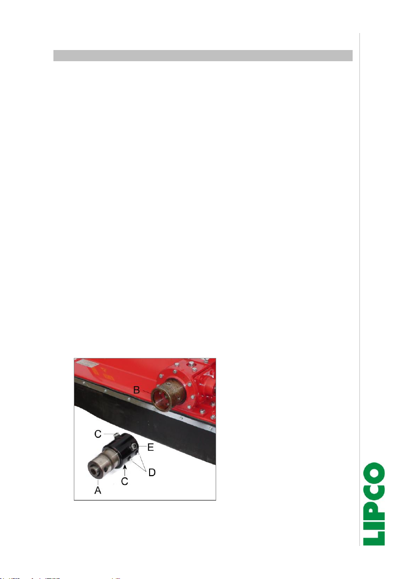
8. Connection to engine-driven machine
We suggest that before attaching the drive flange (Fig. 1 Ref A), to
apply machine grease to the outer diameter of the machine flange
(Fig. 1 Ref B).
Attach then the drive flange using the two set screws (Fig. 1 Ref C)
and the lock nuts on.
Attach drive flange as follows:
•Adjust both threaded pins with attached drive flange to a dis-
tance of approx. 5 mm to the machine flange (Fig. 1 Ref B).
•Check if after tightening the two lock nuts the drive flange can
swivel free and without blocking.
•Make sure, that the gearing of the LIPCO ME correctly engages
thePTO gearing of the drive and the drive flange is centrally ap-
plied to the motor unit.
•Then secure the connection between the equipment and the
prime mover.
•Before starting to work lubricate the drive flange on the two
grease nipples. (Fig. 1 Ref D).
Abb. 1
Instructions
Flail mower ME 70/80/90/104/120/140..L
14 - 40
110725-E-03-EN BA ME-70-80-90-104-120-140-L / 05/11/2019
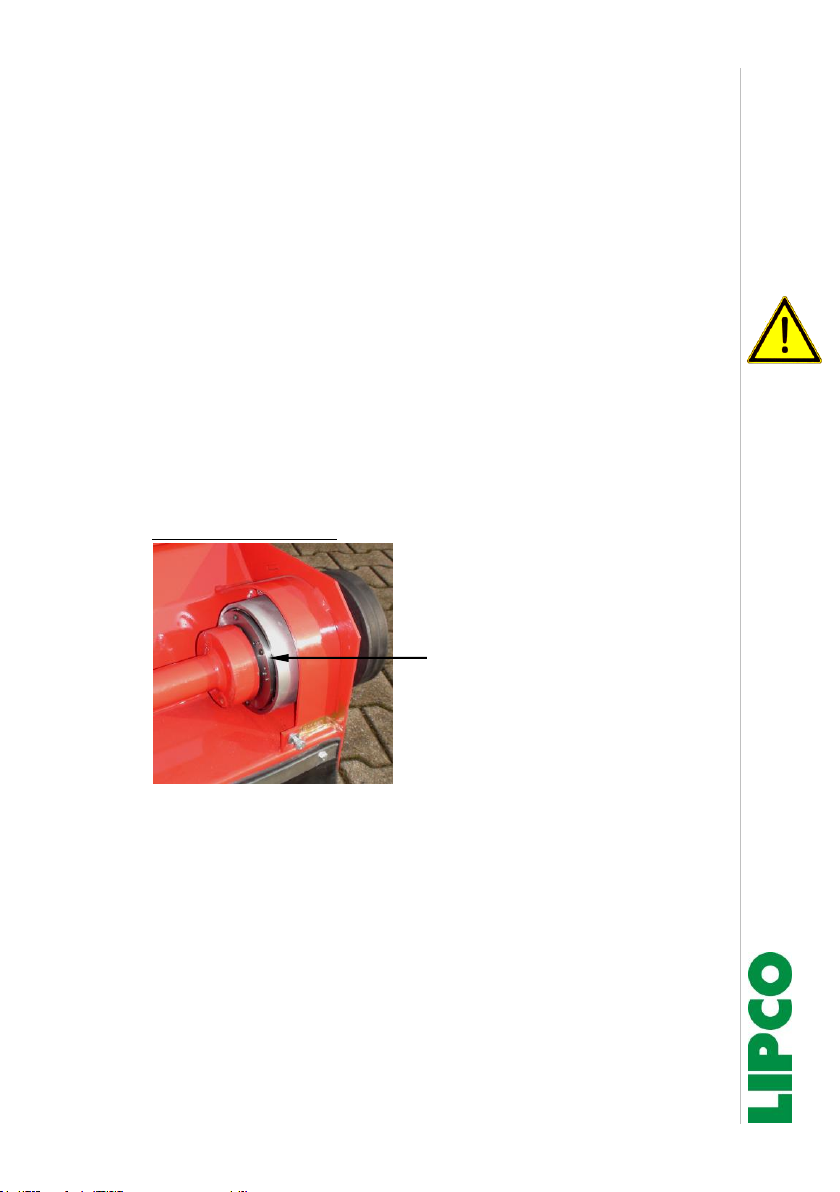
The LIPCO ME can oscillate +/- 3 degree to adapt to uneven
ground. To allow this oscillation, the machine flange (B) has two
slots, in which both set screws (C) engage.
If this oscillation is not desired, this function can be bridged via a
lateral clamping screw (E).
To bridge this function, turn the screw (E) in until you feel re-
sistance. Then secure the screw with the lock nut.
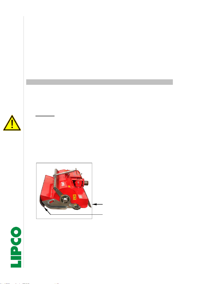
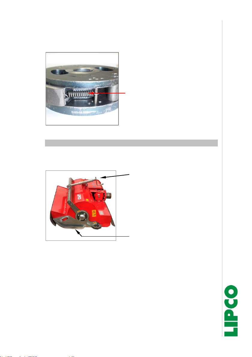
9. Application instructions
•In order to achieve a uniform mulching result, the Flail mower
must roll on the roller or on the supporting wheels during the
mulching work.
Warning:
When working with the Flail mower in a lifted position, there is a
risk due to falling rocks.
•When working close to streets, paths or residential areas, you
have to work with particular caution!
Never work without stone guard! (Fig. 2)
Rear stone guard
Front stone guard
Fig. 2
•For your own safety, you should always wear safety shoes and
safety goggles while working.
Instructions
Flail mower ME 70/80/90/104/120/140..L
15 - 40
110725-E-03-EN BA ME-70-80-90-104-120-140-L / 05/11/2019
•Check at each start-up slow-down time of the blade brake.
To test the blade brake, run the machine with maximum engine
and PTO speed. After pressing the clutch lever or the PTO
switch, the blade shaft has to stop within 4 - 7 sec.
If the maximum slow-down time (7 sec.) is exceeded, the blade
brake must be checked.
It is not allowed to run the machine with exceeded slow-down
time.
Note:
It is not recommended to run the machine with slow-down time
lower than 4 sec. Running the machine with slow-down time
shorter than 4 sec. can create excessive overload on the belts
and leading thus to premature failure of the machine.
position blade brake:
Fig. 3
Instructions
Flail mower ME 70/80/90/104/120/140..L
16 - 40
110725-E-03-EN BA ME-70-80-90-104-120-140-L / 05/11/2019
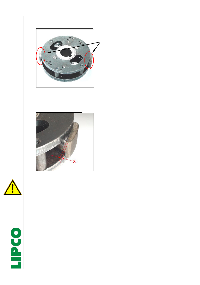
Blade brake disassembled:
Brake lining –(2x)
180° offset
Fig. 4
•Check height of brake lining
Height of brake lining:
Minimum height “X“ at the end of
the brake lining is:
1.0 mm.
If dimension "X" falls too low, the
blade brake must be replaced by
a LIPCO original diameter
brake.
Abb. 5
The blade brake is a safety-relevant component.
Repair by customer / user is not allowed.
Instructions
Flail mower ME 70/80/90/104/120/140..L
17 - 40
110725-E-03-EN BA ME-70-80-90-104-120-140-L / 05/11/2019
•Check for problems with the blade brake also, if the return
springs of the brake pads are correctly hooked or not broken.
Tension spring (2x), 180° off-set
Fig. 6
9.1. Cutting height adjustment
•Cutting height can be adjusted by the spindle.
•Adjusting the spindle will move the height of the support roller.
Spindle
Parallel to the movement of the
support roller, both skids will
move up / down.
Skids on both sides.
Fig. 7
Instructions
Flail mower ME 70/80/90/104/120/140..L
18 - 40
110725-E-03-EN BA ME-70-80-90-104-120-140-L / 05/11/2019
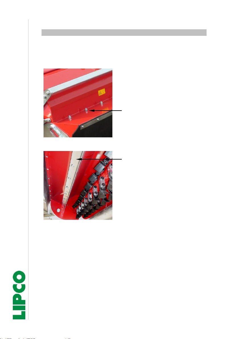
9.2. Blow bar adjustment
•The length of the mulch material can be influenced by the posi-
tion of the blow bar. This can be done by positioning the blow bar
closer or more far off the cutting blades
To adjust the blow bar, loosen
the lock nuts on the top of the
machine.
After moving the blow bar in-
side the machine to the desired
position, tighten the lock nuts
on top of the machine firmly
again.
Fig. 8
Blow bar inside the machine
Fig. 9
•Make sure when replacing the blow bar to the correct position,
that the bended side of the blow bar is directed to the cutter
blades - see Figure 9
•Check the blow bar regularly for damage.
Replace a damaged blow bar as it may adversely affect the cut-
ting results.
Instructions
Flail mower ME 70/80/90/104/120/140..L
19 - 40
110725-E-03-EN BA ME-70-80-90-104-120-140-L / 05/11/2019
10. Replacing the cutter blades
In order to achieve an optimal mulch result, it is important that the
cutter blades are in perfect condition. The cutter blades are designed
with a cutting edge on front and back side.
This allows, with worn cutting edge, to turn the blade by 180°, by
changing cutter blade position from left to right side and vv.
Using a cutter blade with 2 cutting edges doubles the lifetime in
comparison to a cutter blade with only one cutting edge.
•On both sides worn cutter blades should be replaced.
•Changing the cutter blades, use only new lock nuts.
Already built in lock nuts will lose their safety function, once
removed and used again.
•Use only designated set screws –refer to spare parts list.
Screws completely threaded will lead to increased wear of
the screws and the blade support.
•Replacing worn cutter blades, set screws, mounting plates,
washer and safety nuts have to be replaced parallel.
•Cutter blades can be replaced in pairs, by removing the cor-
responding lock nuts and set screws.
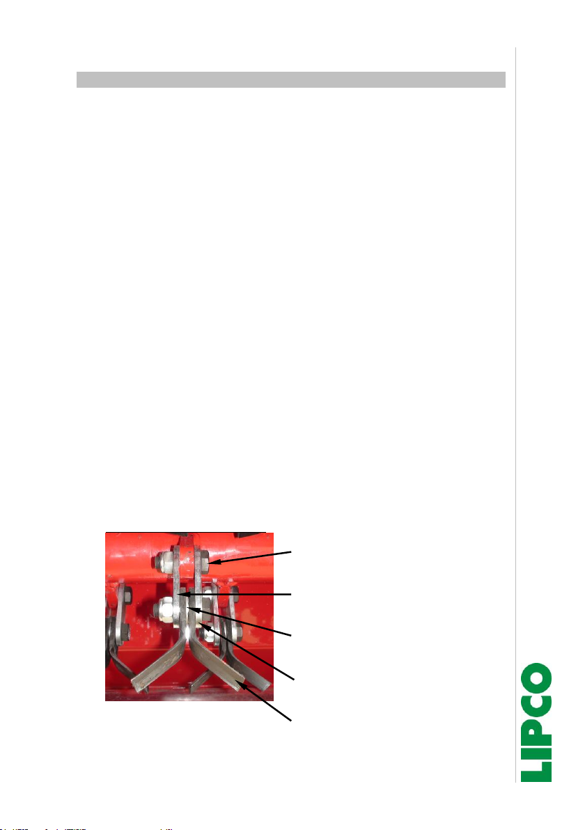
Cutter blade replacement:
Set screw +
Flat safety nut
Threaded mounting plate on
safety nut side
Washer between both cutter
blades.
Mounting plate (non threaded)
on screw head side.
Cutter blade
Fig. 10

Instructions
Flail mower ME 70/80/90/104/120/140..L
20 - 40
110725-E-03-EN BA ME-70-80-90-104-120-140-L / 05/11/2019
•Assembly has to be done as shown see fig. 10
•Threaded mounting plate has to be positioned under safety nut
and is used to tighten the lock nuts.
•Tighten the lock nuts so that the cutting blades still can swing
freely.
•Tightening the lock nuts to much avoids free swinging of the cut-
ting blades, with negative impact on cutting result.
•Note:
Use only original LIPCO spare parts!
•Note:
Working on the mower, make sure that the machine is secured
against unintentional tilting!
Use suitable mechanical support, when working on lifted ma-
chine.
This manual suits for next models
5
Table of contents


