Lippert Components SolidStep 3.0 Lift Assist User manual

SolidStep® 3.0 Lift Assist
OEM INSTALLATION MANUAL

Rev: 07.18.18 Page 2 CCD-0001653
System Information
The SolidStep® 3.0 is a trailer entry step assembly that can be mounted to the side of any trailer, providing
an ease of entry, regardless of level ground. The suggested floor height range should be between 35-44" for
a 4-step tread and 27-36" for a 3-step tread.
Safety Information
The step assembly was designed for an operational weight rating of 400 lbs.
TABLE OF CONTENTS
System Information 2
Safety Information 2
Resources Required 3
Prior to Installation 3
Installation 3
Place Assembly Inside Doorframe 3
Adjust Transport Lock 4
Secure Hinge Plate 5
Attach Strut 6
Operation 7
Adjust Leg Extensions 7
Moving parts can pinch, crush or cut. Keep clear and use caution.
No repairs should be attempted by anyone other than a qualied professional. The deployment and
retraction of the step assembly can cause injury if proper precautions are not taken.
Always wear eye protection when performing service or maintenance to the trailer. Other safety
equipment to consider would be hearing protection, gloves and possibly a full face shield, depending on
the nature of the service.
Failure to follow the instructions provided in this manual may result in death, serious injury, trailer
damage or voiding of the component warranty.

Rev: 07.18.18 Page 3 CCD-0001653
Resources Required
• 1 to 2 Persons, depending on task
• Cordless or Electric Drill or Screw Gun
• Appropriate Drive Bits
• Tape Measure
• Backer Plate with Appropriate Fasteners
• #10 - 1 ½" Self-Tapping Screws (laminate floor) or #10 - 1 ½" Wood Screws (wood floor)
• #10 Self-Tapping Screws (aluminum stud wall construction) or #10 Wood Screws (wood stud wall
construction) of appropriate length to penetrate the wall stud depth by at least 75 percent
Prior to Installation
Prior to installation, verify that the trailer is on level or near level ground.
1. Secure OEM-supplied wooden backer beam, or comparable structural substitute, underneath the sub-
floor in front of the doorway where the step hinge plate will be attached.
2. The backer beam should be 1” to 2” thick and at least as wide as the hinge plate.
NOTE: The backer beam provides better penetration for the screws and helps prevent damage to the floor
if the step is improperly deployed.
3. Make sure the trailer is parked on solid, level ground.
4. Chock trailer tires to prevent unwanted movement during component installation.
Installation
Place Assembly Inside Doorframe
1. With the steps extended, and in the down position, place the assembly inside the unit's doorframe.
Verify with a tape measure that the assembly is centered in the doorframe.
NOTE: Make sure the step threshold plate is placed firmly against the outside of the door threshold (Fig.
1A). If not positioned flush against the outside of the door threshold, the step assembly could
prevent the door from closing.
2. Remove the two plastic caps from the alignment cover holes in the mounting plate (Fig. 1B).
3. With the step assembly still in the extended position, install two fasteners, either #10 - 1 ½" self-
tapping screws (laminate floor) or #10 - 1 ½" wood screws (wood floor), into the hinge plate's
alignment cover holes (Fig. 1B) in the mounting plate.
4. After the two fasteners are installed, carefully lift the step assembly to the upright stored position. If
the latching mechanism doesn't engage, it will need to be adjusted to operate properly. At this point,
have another person hold the step assembly from inside the trailer, then do the "Adjust Transport
Lock" procedure.
Fig. 1
B
A
Rev: 07.18.18 Page 4 CCD-0001653
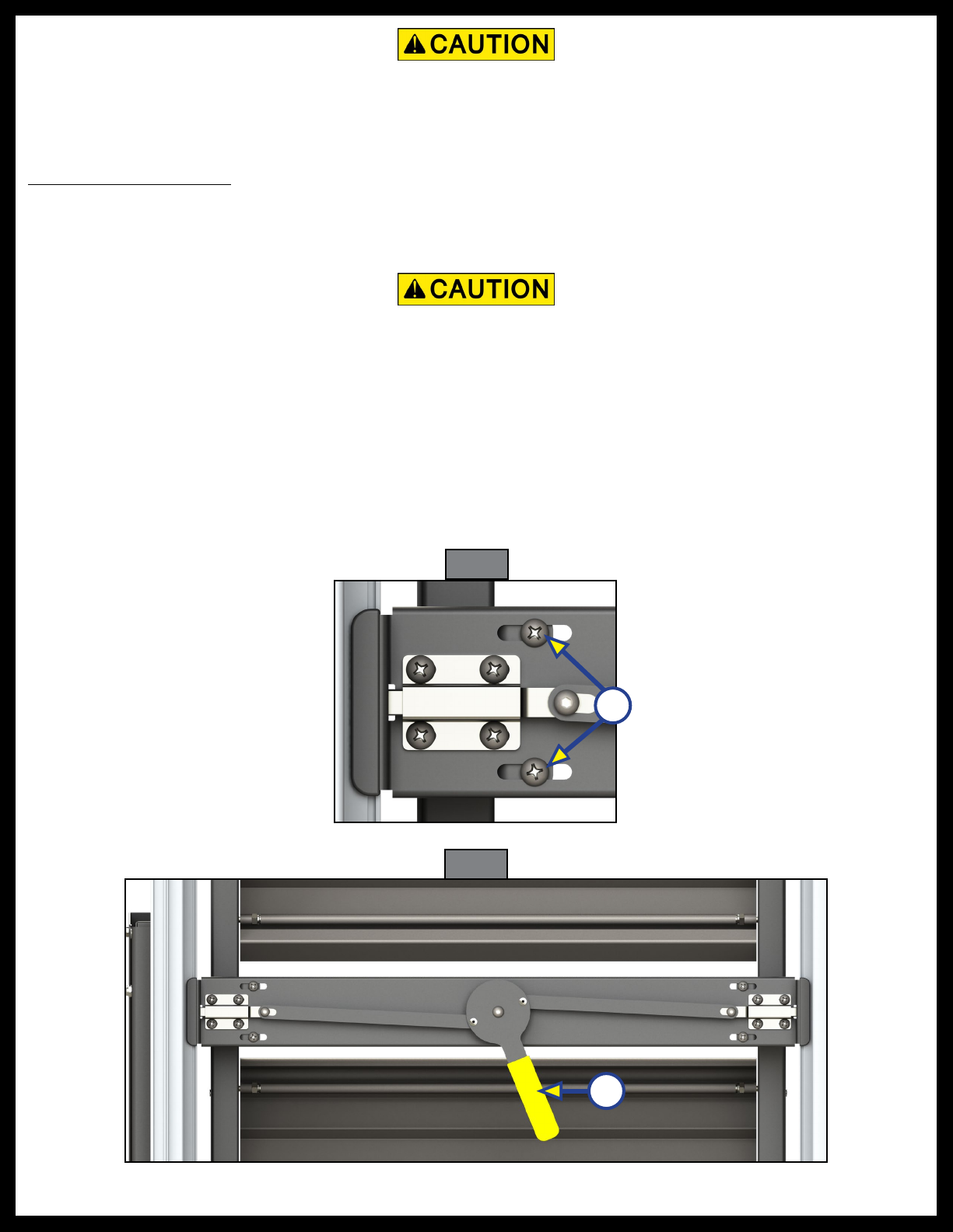
Adjust Transport Lock
1. If adjustment is required, loosen the two bolts (Fig. 2A) on both sides of the transport lock. This allows
for up to a ½" of adjustment either way in the latch mechanism.
2. After the transport lock has been correctly positioned, tighten the bolts.
A
Fig. 2
A
Fig. 3
3. After the transport lock has been adjusted, test its functionality by shaking the step assembly to
simulate road vibration.
4. Engage and disengage the transport lock (Fig. 3A) to make sure the latch flanges do not scrape against
the doorframe.
NOTE: To make minor adjustments, it may be necessary to loosen the original two fasteners installed in
the hinge plate during placement of the assembly in the doorframe. Refer to step 3 in the "Place
Assembly Inside Doorframe" section.
Do not attempt to lock the step in place, as the latching mechanism may need to be adjusted to the
proper left-right orientation and tightened in position before using the transport lock. Attempting
to engage the transport lock without proper adjustment may cause damage to the doorframe or step
assembly.
Do not overtighten the bolts. Overtightening the bolts may damage the threads in the sheet metal or
cause the bolt heads to break o.

Rev: 07.18.18 Page 5 CCD-0001653
Secure Hinge Plate
1. After adjusting the transport lock and with the step assembly in the upright stored position, secure the
hinge plate (Fig. 4A) to the floor of the trailer using nine additional fasteners; either #10 - 1 ½" self-
tapping screws (laminate floor) or #10 - 1 ½" wood screws (wood floor). Use the horizontal slots
(Fig. 4B) to make additional small adjustments of the step assembly in the doorframe.
NOTE: An optional OEM-supplied step threshold transition piece (Fig. 4C) may be installed to cover the gap
between the door threshold and the floor.
2. Extend the step assembly and replace the two plastic caps to cover the access holes in the mounting
plate (Fig. 5A).
A
A
B
Fig. 4
Fig. 5
C
Rev: 07.18.18 Page 6 CCD-0001653
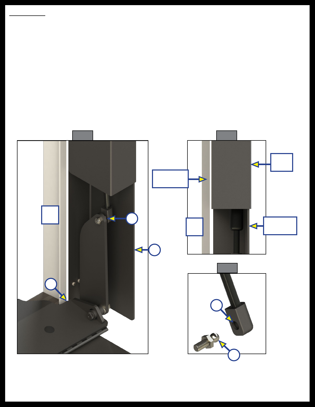
Attach Strut
1. Remove the trim on the inside of the doorframe where the strut mounting bracket is to be installed.
NOTE: Door trim removal is a requirement to prevent interference issues. The trim may be cut to length
and installed so that it ends 28 ⁄" above the floor on the strut side of the doorframe.
2. Place the strut mounting bracket (Fig. 6A) into position. The mounting bracket should be flush against
the wall and the floor (Fig. 6B), but placed with a ½" gap along the aluminum doorframe extrusion
(Figs. 6 and 7). The strut cover will have a ⁄" clearance along the aluminum doorframe extrusion.
NOTE: The floor under the strut mounting bracket has been removed for clarity.
3. Secure the strut mounting bracket using eight screws, either #10 self-tapping screws (aluminum
stud wall construction) or #10 wood screws (wood stud wall construction). The screws should be of
appropriate length to penetrate the wall stud depth by at least 75 percent.
4. Attach the strut (Fig. 6C) to the top of the step's cam angle load bracket. Push the end of the strut (Fig
8A) onto the ball stud (Fig. 8B) until it snaps into place.
NOTE: The strut can be removed by using a flathead screwdriver to pry back the spring clip on the strut end.
Fig. 6 Fig. 7
A
B
A
C
B
Fig. 8
½"
Gap ½"
Gap
Doorframe
Extrusion
Strut
Cover
Mounting
Bracket

Rev: 07.18.18 Page 7 CCD-0001653
Operation
Adjust Leg Extensions
After extending the step assembly, the leg extensions (Fig. 9A) can be adjusted. The leg extensions are
secured with spring loaded, self-latching levers (Fig. 9B). Adjustments can be made to the leg extensions
in 1" increments (Fig. 9C) by moving the inner legs up or down for the optimal angle and to adjust for the
ground surface angle.
1. To extend the inner leg:
A. Lift the self-latching lever (Fig. 9B) and extend the inner leg to the ground and at an angle so the
step foot is parallel to the ground and level.
B. Place the lever in the closest slot.
2. Prior to using the step assembly, step on a tread to test its functionality and integrity.
3. To retract the inner leg:
A. Remove the self-latching lever from the slot.
B. Retract the inner leg.
C. Replace the lever in last slot.
B
Fig. 9
A
C

The contents of this manual are proprietary and copyright protected by Lippert Components, Inc. (“LCI”).
LCI prohibits the copying or dissemination of portions of this manual unless prior written consent from an
authorized LCI representative has been provided. Any unauthorized use shall void any applicable warranty.
The information contained in this manual is subject to change without notice and at the sole discretion of LCI.
Revised editions are available for free download from lci1.com.
Please recycle all obsolete materials.
For all concerns or questions, please contact
Lippert Components, Inc.
Table of contents
Popular Camping Equipment manuals by other brands


Crivit
Crivit 273821 Instructions for use

Quest Leisure Products
Quest Leisure Products Childrens Dinosaur 5203T instructions

Caravan
Caravan SPORT SHELTER Reference manual

Cub
Cub 2.2 Series owner's manual

Clam Corp
Clam Corp Fish Trap 8325 instruction manual

Coleman
Coleman Tioga Backpacker 9273A827C instructions