Lite-Puter EDX-1210 User manual

EDX-1210/EDX-620 [EUM-D] 1
User Manual
EDX-1210/EDX-620
12/6 Channel Dimmer Pack

EDX-1210/EDX-620 [EUM-D] 2
INDEX
0 CAUTION.........................................................................................................................................3
1 INTRODUCTION...............................................................................................................................4
1-1 FEATURES...........................................................................................................................................4
1-2 SPECIFICATIONS...................................................................................................................................4
1-3 DP-E01 INTRODUCTIONS .....................................................................................................................5
1-4 DIMMING MODULE INTRODUCTIONS.......................................................................................................6
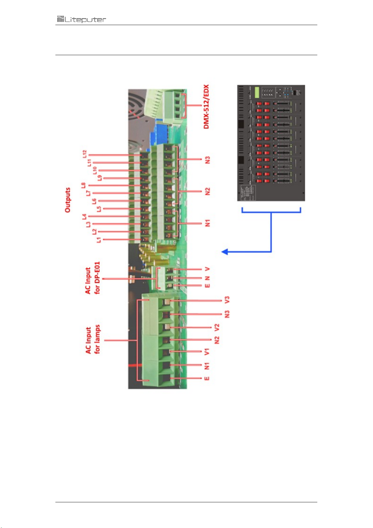
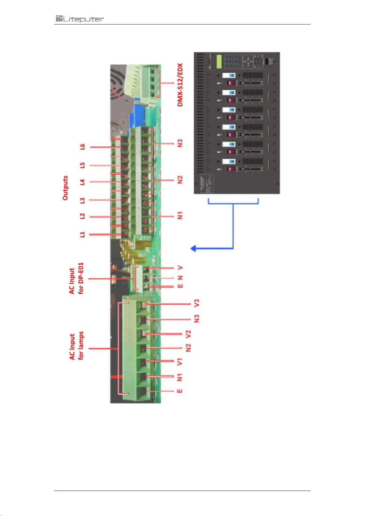
1-5 OUTPUT TERMINALS (EDX-1210)/(EDX-620) ........................................................................................7
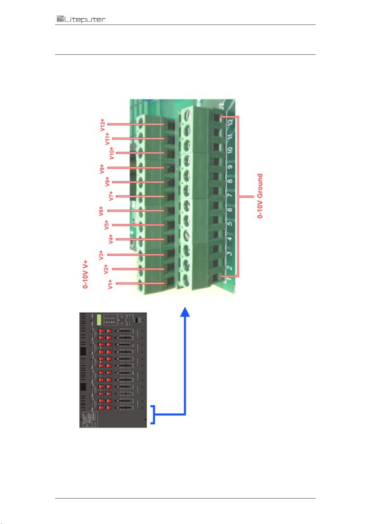
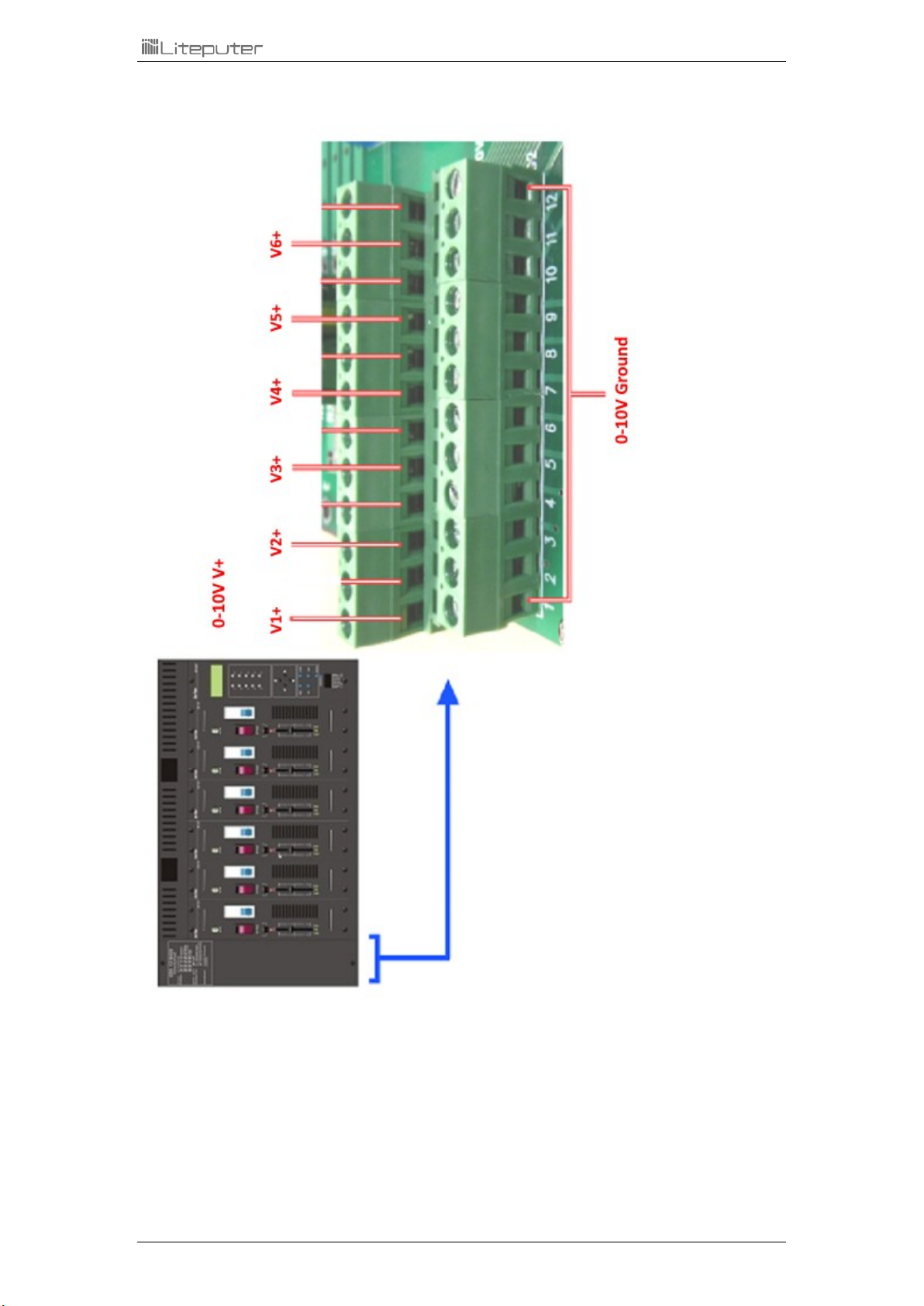
1-6 ANALOG (0-10V DC) OUTPUT TERMINALS (EDX-1210)/(EDX-620)..........................................................9
1-7 DIMENSION......................................................................................................................................11
2 OPERATIONS .................................................................................................................................12
2-1 FUNCTION LIST..................................................................................................................................12
2-2 INITIALIZATION ..................................................................................................................................13
2-3 DMX-512 START ADDRESS SETTING.....................................................................................................14
2-4 ID NUMBER SETTING .........................................................................................................................14
2-5 ZONE SETTING ..................................................................................................................................15
2-6 SAVE SCENES ....................................................................................................................................15
2-7 RECALL SCENES .................................................................................................................................16
2-8 CLOCK SETTING .................................................................................................................................16
2-9 TIMER SETTING .................................................................................................................................17
2-10 TIMER ON/OFF SETTING...................................................................................................................18
2-11 FADE TIME SETTING .........................................................................................................................18
2-12 SET THE DIMMING MODE .................................................................................................................18
2-13 CHECK THE DIMMING MODES............................................................................................................19
2-14 PARTITION SETTING..........................................................................................................................20
2-15 PARTITION ON/OFF SETTING .............................................................................................................21
2-16 BYPASS SETTING ..............................................................................................................................22
2-17 MIX (OVERLAP)SETTING ..................................................................................................................22
2-18 TEMPERATURE ................................................................................................................................22
2-19 LCD OFF TIME SETTING....................................................................................................................23
2-20 SET MINIMUM LEVEL OF EACH OUTPUT...............................................................................................23
2-21 MODULE BYPASS .............................................................................................................................23
2-22 MODULE CHECK..............................................................................................................................24
2-23 BACKUP DATA .................................................................................................................................24
2-24 RESTORE DATA ................................................................................................................................24
LIMITED WARRANTY ........................................................................................................................25

EDX-1210/EDX-620 [EUM-D] 3
0 Caution
0-1 Dimming or Switching Setting
1. Each channel must be set 1.dimming 2.non-dimming (switching) 3.fluorescent before connecting
to the load.
2. Non-dimming lamps, for example, non-dimmable fluorescent lamps, mercury lamps, high (low)
pressure sodium lamps, compound metal lamps or other lamps with motor, can be damaged
when being set as dimmable. Please refer to 2-12.
0-2 Instruction of Load Power
In order to maintain the operation of EDX-1210 / EDX -620, please follow the instructions as below:
EDX -1210 / EDX -620 must keep decent ventilation. Overheating will lead to EDX -1210 / EDX -620 to
stop output to protect itself.
0- 3 Operating Circumstance
Room temperature: < 35°C
Humidity: 40% ~ 80%

EDX-1210/EDX-620 [EUM-D] 4
1 Introduction
1-1 Features
1. EDX-1210: 12 channels. Maximum output of each channel is 10A
EDX-620: 6 channels. Maximum output of each channel is 20A
2. EDX, DMX-512 compatible
3. Square-law dimming curve (C2.0 dimming curve)
4. Adjustable fade in/out time
5. Build-in timer
6. Each channel can be set as dimming /non-dimming/fluorescent mode.
7. LCD display
8. Button lock/unlock function
9. Up to 99 zones.
10. Can be recalled scene by external controllers or scene control panels.
1-2 Specifications
1. Input: AC 100 –240V
2. Output:
EDX-1210: 10A per channel (max)
EDX-620: Output: 20A per channel (max)
3. Protocol: EDX/ DMX-512
4. Dimension: 492(W) x 350(H) x 125(D) mm
5. Weight: 12 kg

EDX-1210/EDX-620 [EUM-D] 5
1-3 DP-E01 Introductions
1
【0】-【9】
2
【】,【】,【】,【】
3
【DMX】,【ZONE】,【VR】,【FNC】,【ENTER】
4
DMX-512 Input/ RS-485

EDX-1210/EDX-620 [EUM-D] 6
1-4 Dimming Module Introductions
1
ON/OFF
2
Output Bypass
3
Dimming Mode Selection
D: Leading-edge dimming
S: Switch (On/Off)
F: Fluorescent ( 0-10V DC)
4
Dimming Sliders

EDX-1210/EDX-620 [EUM-D] 7
1-5 Output Terminals (EDX-1210)/(EDX-620)
EDX-1210

EDX-1210/EDX-620 [EUM-D] 8
EDX-620

EDX-1210/EDX-620 [EUM-D] 9
1-6 Analog (0-10V DC) Output Terminals (EDX-1210)/(EDX-620)
EDX-1210

EDX-1210/EDX-620 [EUM-D] 10
EDX-620

EDX-1210/EDX-620 [EUM-D] 11
1-7 Dimension

EDX-1210/EDX-620 [EUM-D] 12
2 Operations
2-1 Function List
After turning on the power, press 【FNC】to enter main menu and press 【】or【】to select
function,

EDX-1210/EDX-620 [EUM-D] 13
F 1
DMX-512 starting address setting
F 2
ID number setting
F 3
Zone setting
F 4
Clock setting
F 5
Time setting
F 6
Timer on/off setting
F 7
Scene fade time setting
F 8
Check dimming mode (DIM/SW/FLU) of each channel
F 9
Partition setting
F10
Partition on/off setting
F11
DMX-512 bypass function
F12
Mix (overlap) on/off setting
F13
Temperature detection funciton
F14
LCD backlight off setting
F15
Set minimum level of each output channel
F19
Data backup
F20
Data restore
F21
Initialization
2-2 Initialization
STEP-1: Press 【FNC】to enter the menu. Select "F21: INITIAL", and LCD shows:
STEP-2: Press【】,【】to select Yes or No.
STEP-3: Press 【ENTER】to do initialization.

EDX-1210/EDX-620 [EUM-D] 14
2-3 DMX-512 Start Address Setting
Although we would recommend applying RS- 485 rather than DMX-512 on EDX systems,
EDX-1210 is still compatible with DMX-512. Note that DMX-512 controllers have higher priority
than other EDX controllers.
STEP-1: Press 【FNC】to enter the menu. Select "F1: DMX_ADR", and LCD shows:
STEP-2: Press【】or【】to set DMX-512 starting address.
STEP-3: Press 【ENTER】to save the setting or press【FNC】to exit.
1. In DMX mode, there are 512 channels available for start channel address setting.
Example: (Each EDX-1210 can output 12 channels continuously.)
DMX Start Address: 001, its DMX signal can output from channel 1 to channel 12 continuously.
DMX Start Address: 007, its DMX signal can output from channel 7 to channel 18 continuously.
2. Duplicated DMX address is available. That is, two or more EDX-1210s can be set to the
same DMX address.
2-4 ID Number Setting
Each EDX series device must have an ID number (The default setting is 001.). When one
device’s working alone, there is no need to adjust the ID number, but when several devices’
working together, each device must have a different ID number.
STEP-1: Press 【FNC】to enter the menu. Select "F2: ID SET ", and LCD shows:
STEP-2: Press【】or【】to set the ID number.
STEP-3: Press 【ENTER】to save the setting or press【FNC】to exit.

EDX-1210/EDX-620 [EUM-D] 15
2-5 Zone Setting
Definition of zone: In EDX system, the device must set the zone number before using, which
consists of two parts, one is the zone number and another is the start channel.
For example: There are 4 EDX-1210 (48 channels in total) in zone 1, the zone number of each
device should be 01-01,01-13,01-25,01-37 respectively.
STEP-1: Press 【FNC】to enter the menu. Select "F3: ZONE SET ", and LCD shows:
The two digit number, "01", is zone number. The three digit number, "001", is the starting channel.
STEP-2: Press 【】or 【】to select between zone and start channel. Press【】or【】to set
the number.
STEP-3: Press 【ENTER】to save the setting or press【FNC】to exit.
2-6 Save Scenes
STEP-1: Set EDX-1210 the dimming levels by the dimming sliders. For example, set channel 1 to 4 as
100% and set channel 5 to 8 as 50%;Set EDX-620 the dimming levels by the dimming sliders. For
example, set channel 1 to 4 as 100% and set channel 5 to 6 as 50%
STEP-2: Press【】or【】to enter scene editing function.
The LCD shows the current dimming level for each channel as (EDX-1210)12 and (EDX-620) 6 bars.
STEP-3: To further adjust the dimming level, press【】or【】to select a channel, and press【】
or【】to set the level of the channel.
STEP-4: Pres【ENTER】, LCD shows:
STEP-5: Press【】or【】to select a scene number to save the current dimming levels.

EDX-1210/EDX-620 [EUM-D] 16
2-7 Recall Scenes
1. Press【1】~【6】to recall the 6 scenes directly.
2. Press scene buttons on DP-E01 control plate (optional) to recall the scene.
If SC1 ~ SC6 was preset with fade time (please check the remark):
Press
【
1
】
~
【
6
】
once to recall the scene smoothly after the fade time.
Press
【
1
】
~
【
6
】
twice to recall the scene directly without the delay time.
2-8 Clock Setting
STEP-1: Press 【FNC】to enter the menu. Select "F4: CLOCK ", and LCD shows the system clock:
STEP-2: Press【】or【】to select year/month/day/weekday/hour/minute/second.
Press【】or【】to set the number.
STEP-3: Press 【ENTER】to save the setting or press【FNC】to exit.

EDX-1210/EDX-620 [EUM-D] 17
2-9 Timer Setting
2-9-1 Add a Timer
STEP-1: Press 【FNC】to enter the menu. Select "F5: TIMER ", and LCD shows:
STEP-2 Press【1】to add a timer, LCD shows:
STEP-3: Press【】or 【】to select hour/minute/zone number/scene/fade time. Press【】or
【】to set the number. In this example, we add a timer which recalls scene01 in zone02 with 2.0s
fade time at 10:30:
STEP-4: Press【】several times to enter weekday selection.
The LCD shows that the timer is enabled on Monday and Tuesday.
Each digit in the second row represents a weekday.
("x" means that the timer is disabled on the weekday; "1" means that the timer is disabled on the
weekday)
STEP-5: Press【】or 【】to select a weekday, press【】or【】to enable or disable the timer
on the selected weekday.
In this example, we make the timer enabled every day:
STEP-6: Press 【ENTER】to save the setting or press【FNC】to exit.

EDX-1210/EDX-620 [EUM-D] 18
2-10 Timer On/Off Setting
STEP-1: Press 【FNC】to enter the menu. Select "F6: TIMER ", and LCD shows:
STEP-2: Press【】or 【】to select timer on or timer off. Press【】or【】to set the number.
STEP-4: Press【ENTER】to save the setting or press【FNC】to exit.
2-11 Fade Time Setting
STEP-1: Press 【FNC】to enter the menu. Select "F7: FADE SET ", and LCD shows:
STEP-2: Press【】or【】to select scene number or fade time. Press【】or【】to set the number.
STEP-3: Press 【ENTER】to save the setting or press【FNC】to exit.
2-12 Set the Dimming Mode
To set the dimming mode, please use the slide switch on the panel of the dimming module.
D: Leading edge dimming
S: Switch mode (on/off)
F: Fluorescent mode (0-10V DC)

EDX-1210/EDX-620 [EUM-D] 19
2-13 Check the Dimming Modes
(EDX-1210) STEP-1: Press 【FNC】to enter the menu. Select "F8: DIM/SW ", and LCD shows:
The LCD shows that channel 1 - 4 are in leading-edge dimming mode, "D"; channel 5 - 8 are in switch
mode; channel 9 - 12 are in fluorescent mode.
D: Leading edge dimming
S: Switch mode (on/off)
F: Fluorescent mode (0-10V DC)
(EDX-620) STEP-1: Press 【FNC】to enter the menu. Select "F8: DIM/SW ", and LCD shows:
The LCD shows that channel 1 - 2 are in leading-edge dimming mode, "D"; channel 3-4 are in switch
mode; channel 5 - 6 are in fluorescent mode.
D: Leading edge dimming
S: Switch mode (on/off)
F: Fluorescent mode (0-10V DC)

EDX-1210/EDX-620 [EUM-D] 20
2-14 Partition Setting
Usually, a EDX device can be set only one zone number. To make EDX system more flexible,
by partition function, a EDX device can set each of its channels as different zone number. The
function is useful only when partition on/off is set to on (please refer 2-14).
2-14-1 Application of Partition Function
If the device is a 4 channel dimmer and there are two rooms, each room needs 2 channels, the
partition function is able to divide the 4 channels into 2 parts. Channel 1 to 2 are in partition 1 (zone
1); channel 3 to 4 are in partition 2 (zone 2). Install two controllers in each room, one is set to zone 1;
the other is set to zone 2, and then you can control channel 1 and 2 by controller 1 and control
channel 3 and 4 by controller 2.
This manual suits for next models
1
Table of contents
Other Lite-Puter Dj Equipment manuals
Popular Dj Equipment manuals by other brands

Art Lighting Production
Art Lighting Production ASTERION II Series user manual

Briteq
Briteq Pro Beamer RGBW outdoor Operation manuals

Stageline
Stageline LE-182LED instruction manual

thomann
thomann STARVILLE Mini Stage Par 7x6W RGB user manual

JB-Lighting
JB-Lighting SPARX 7 operating instructions

Showgear
Showgear VIBE FX Strike manual