Power section
Ok, let’s first address the elephant in the room, the power section. As almost all vintage fuzzes, this
one also uses positive ground (yes, yes, technically there is no such thing as positive ground). All
purists say you should only use a battery preferably one that is close to death. For them the
consistent -9V kills the fuzzy sound. Well… this effect has a surprise for them!
This effects power section is designed to accommodate all sorts of power. Let’s take a look at all the
possibilities.
Battery only
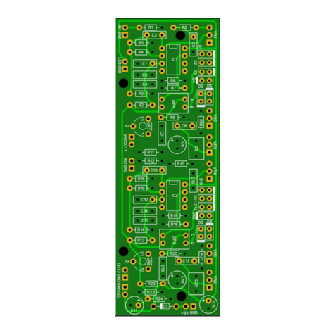
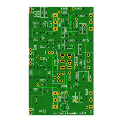
Do not solder IC1,C1 to C4,D1,D2,VR1 and R7 and SW1. That should save you money! Instead you
should solder the BLACK wire of the battery to the octagonal pad of SW1 and the RED wire to the
Ring of the stereo input jack. Also the status LED needs to be reversed! Take a good look at the off
board wiring section!
Switchable Voltage Inverter
The PCB incorporates a built in voltage inverter so you can daisy chain it with other (negative ground)
effects. It has a nice extra feature that can simulate a dying battery by using a sag pot (VR1). You can
use this as a “set and forget” by installing an internal 6mm trim pot or as an extra external 16mm sag
pot so you can easily adjust the sag during play. With the current R7 at 4k7 you can turn down the
voltage to approximately -3V. If you want to go down to 0V you can just solder a jumper instead of a
resistor in R7. If you want a higher minimum voltage then you can install a higher resistor in R7 (eg.
10k will result in approximately -4,5V). PS my personal favorite voltage setting is around -4,6V.
By installing SW1 you can switch between -9V and the sag voltage. Make it an external switch so you
can use it during play or leave it internal to “set and forget”. You can also leave out SW1 and only use
the sag as an external pot. If you turn the pot all the way to the left it will give you the whole -9V and
if you turn it to the right it will give you the sag (amount dependent on the resistor used in R7 as
mentioned before). If you want to do this then do not forget to solder a jumper between the right
pad of SW1 and the center octagonal pad.
Also you can choose to use the inverter just to deliver a constant -9V. To do so, just leave out SW1,
VR1 and R7 and solder the left pad of SW1 to the center octagonal pad.
NEVER let the outer 2 lugs of SW1tough each other and also never connect all 3 pins of SW1
together. If the IC gets hot then there is a short in the power section and you must disconnect the
effect immediately from the adapter and find the fault.

