Littelfuse MPS User manual

MPS MANUAL
MOTOR PROTECTION SYSTEM
Revision 6-F-022117
Copyright ©2017 by Littelfuse Startco
All rights reserved.
Document Number: PM-1130-EN

Factory default password is 1111
New Password
See Section 4.3.6.
Motor Identification

Page ii
MPS Motor Protection System Rev. 6-F-022117
. Table of Contents
TABLE OF CONTENTS
SECTION PAGE
List of Figures ....................................................................... iv
List of Tables ........................................................................ iv
Disclaimer .............................................................................. v
1 Introduction.......................................................... 1-1
1.1 General .................................................................... 1-1
1.2 MPS Features.......................................................... 1-1
1.2.1 Protection .................................................... 1-1
1.2.2 Control – Starting Methods........................ 1-1
1.2.3 Metering...................................................... 1-1
1.2.4 Data Logging .............................................. 1-1
1.2.5 Inputs and Outputs...................................... 1-1
1.2.6 MPS-OPI Operator Interface ..................... 1-2
1.2.7 MPS-RTD Module ..................................... 1-2
1.2.8 MPS-DIF Differential Module................... 1-2
1.2.9 Communications Interface ......................... 1-2
1.3 Ordering Information.............................................. 1-2
2 Installation ............................................................. 2-1
2.1 General .................................................................... 2-1
2.2 MPS-CTU Control Unit ......................................... 2-1
2.3 MPS-OPI Operator Interface.................................. 2-1
2.4 MPS-RTD Module ................................................. 2-1
2.5 MPS-DIF Differential Module............................... 2-1
2.6 Earth-Fault CT’s ..................................................... 2-1
3 System Wiring....................................................... 3-1
3.1 General .................................................................... 3-1
3.2 Wiring Connections................................................ 3-1
3.2.1 MPS-CTU Connections ............................. 3-1
3.2.1.1 Supply Voltage .............................. 3-1
3.2.1.2 Current Inputs................................ 3-1
3.2.1.3 Voltage Inputs ............................... 3-1
3.2.1.3.1 Direct Connection........ 3-3
3.2.1.3.2 1-PT Connection.......... 3-3
3.2.1.3.3 2-PT Connection.......... 3-3
3.2.1.3.4 3-PT Connection.......... 3-3
3.2.1.4 Digital Inputs .................................3-3
3.2.1.4.1 DC Operation............... 3-4
3.2.1.4.2 AC Operation............... 3-4
3.2.1.4.3 Combined AC and
DC Operation ............................... 3-4
3.2.1.4.4 Tachometer
Input (HSI) ................................... 3-4
3.2.1.5 Analog Input (AN IN)................... 3-4
3.2.1.6 Analog Output (AN OUT)............ 3-4
3.2.1.7 PTC Input ...................................... 3-4
3.2.1.8 IRIG-B Input .................................3-4
3.2.1.9 I/O Module Communication......... 3-4
3.2.1.10 RS-485 Network
Communications......................................... 3-4
3.2.2 MPS-OPI Connections and
Address Selection ....................................... 3-4
3.2.3 MPS-RTD Connections and
Address Selection ....................................... 3-5
3.2.4 MPS-DIF Connections ............................... 3-5
3.2.4.1 Core Balance .................................3-5
TABLE OF CONTENTS
SECTION PAGE
3.2.4.2 MPS Summation............................3-5
3.2.4.3 DIF Summation .............................3-5
3.2.5 Dielectric-Strength Testing ........................3-5
4 Operation and Setup ............................................4-1
4.1 General ....................................................................4-1
4.2 MPS-CTU ...............................................................4-1
4.2.1 LED Indication ...........................................4-1
4.2.2 Reset Switch................................................4-1
4.2.3 Phase-CT Inputs..........................................4-1
4.2.4 Earth-Fault-CT Input ..................................4-2
4.2.5 Voltage Inputs.............................................4-2
4.2.6 Motor Data ..................................................4-2
4.2.7 Output Relay Assignment ..........................4-2
4.2.8 Digital Inputs 1 to 7 ....................................4-3
4.2.9 Tachometer Input (HSI) .............................4-4
4.2.10 Analog Output.............................................4-4
4.2.11 Analog Input ...............................................4-5
4.2.11.1 Metering only ..............................4-5
4.2.11.2 Protection.....................................4-5
4.2.11.3 Synchronize to ASD....................4-5
4.2.11.4 Motor Speed ................................4-5
4.2.12 Starter ..........................................................4-5
4.2.13 Protection ....................................................4-5
4.2.14 Miscellaneous Configuration .....................4-5
4.2.15 Network Communications..........................4-5
4.3 MPS-OPI.................................................................4-5
4.3.1 General ........................................................4-5
4.3.2 Configuring the MPS-CTU for
OPI Operation .............................................4-5
4.3.3 Starter Control.............................................4-6
4.3.3.1 OPI Control....................................4-6
4.3.3.2 Local Control.................................4-6
4.3.3.3 Remote Control .............................4-6
4.3.4 Metering ......................................................4-7
4.3.5 Messages .....................................................4-7
4.3.5.1 Trip Reset.......................................4-7
4.3.5.2 Status..............................................4-7
4.3.5.3 Data Logging .................................4-9
4.3.5.4 Statistical Data ...............................4-9
4.3.5.5 Emergency Thermal Reset............4-9
4.3.6 Password Entry and Programming.............4-9
4.4 MPS-RTD .............................................................4-10
4.5 MPS-DIF...............................................................4-10
4.6 Waveform Capture ...............................................4-10
5 Protective Functions......................................... 5-1
5.1 General ............................................................... 5-1
5.2 Overload............................................................. 5-1
5.2.1 Thermal Model ....................................... 5-1
5.2.2 Locked-Rotor Times ............................... 5-4
5.2.3 Emergency Thermal Reset...................... 5-4
5.3 Overcurrent ........................................................ 5-4
5.4 Auxiliary Overcurrent ........................................ 5-5
5.5 Reduced Overcurrent ......................................... 5-5
5.6 Jam ..................................................................... 5-5
5.7 Earth Fault.......................................................... 5-5

Page iii
MPS Motor Protection System Rev. 6-F-022117
. Table of Contents
SECTION PAGE
5.8 Current Unbalance.............................................. 5-5
5.9 Phase Loss—Current.......................................... 5-6
5.10 Phase Reverse—Current..................................... 5-6
5.11 Undercurrent....................................................... 5-6
5.12 Overvoltage ........................................................ 5-6
5.13 Voltage Unbalance ............................................. 5-6
5.14 Phase Loss—Voltage ......................................... 5-6
5.15 Phase Reverse—Voltage .................................... 5-6
5.16 Undervoltage ...................................................... 5-7
5.17 Underpower........................................................ 5-7
5.18 Reversepower ..................................................... 5-7
5.19 Power Factor—Quadrant 4................................. 5-7
5.20 Power Factor—Quadrant 3................................. 5-7
5.21 Underfrequency.................................................. 5-7
5.22 Overfrequency.................................................... 5-8
5.23 Starts per Hour/Time Between Starts................. 5-8
5.24 Failure to Accelerate and Underspeed................ 5-8
5.25 Differential Current Protection........................... 5-9
5.26 PTC Temperature ............................................... 5-9
5.27 RTD Temperature .............................................. 5-9
5.28 Hot-Motor Compensation ................................ 5-10
5.29 Analog Input..................................................... 5-10
5.29.1 Protection .............................................. 5-10
5.29.2 Synchronize to ASD ............................. 5-10
5.29.3 Motor Speed.......................................... 5-10
5.29.4 Metering Only....................................... 5-10
6 Starter Functions.............................................. 6-1
6.1 General ............................................................... 6-1
6.2 Starter Timing Sequences................................... 6-4
6.3 Full-Voltage Non-Reversing Starter .................. 6-7
6.4 Adjustable-Speed Drive ..................................... 6-7
6.5 Soft-Start Starter................................................. 6-7
6.6 Full-Voltage Reversing Starter........................... 6-8
6.7 Two-Speed Starter.............................................. 6-8
6.8 Reactor or Resistor Closed-Transition
Starter ............................................................... 6-10
6.9 Slip-Ring Starter............................................... 6-10
6.10 Part-Winding and Double-Delta Starters ......... 6-11
6.11 Soft-Start-With-Bypass Starter ........................ 6-12
6.12 Reactor or Resistor Open-Transition Starter.... 6-12
6.13 Two-Winding Starter........................................ 6-12
6.14 Wye-Delta Open-Transition Starter ................. 6-12
6.15 Autotransformer Closed-Transition Starter...... 6-13
6.16 Wye-Delta Closed-Transition Starter............... 6-13
7 Theory of Operation......................................... 7-1
7.1 Signal-Processing Algorithms............................ 7-1
7.2 Power Algorithm ................................................ 7-1
7.3 Operator Interface (MPS-OPI) ........................... 7-1
7.4 RTD Module (MPS-RTD) ................................. 7-1
7.5 Differential Module (MPS-DIF) ........................ 7-1
7.6 Firmware Diagnostics ........................................ 7-1
8 Communications............................................... 8-1
8.1 Personal-Computer Interface.............................. 8-1
8.1.1 Firmware Upgrade .................................. 8-1
8.1.2 SE-Comm-RIS ........................................ 8-1
SECTION PAGE
8.2 Network Interface............................................... 8-1
8.2.1 RS-485 Communications........................ 8-1
8.2.2 DeviceNet Communications ................... 8-1
8.2.3 Ethernet Communications....................... 8-1
8.2.4 Profibus Communications....................... 8-1
9 Technical Specifications................................... 9-1
9.1 Control Unit (MPS-CTU) .................................. 9-1
9.2 Operator Interface (MPS-OPI)........................... 9-3
9.3 RTD Module (MPS-RTD) ................................. 9-3
9.4 Differential Module (MPS-DIF) ........................ 9-4
10 Warranty........................................................... 9-5
Appendix A MPS-OPI Menu Map............................ A-1
Appendix B MPS Set-Up Record .............................. B-1
Appendix C MPS Modbus Protocol.......................... C-1
Appendix D MPS A-B DF1 Protocol......................... D-1
Appendix E Communications Database Table .........E-1
Appendix F Register Formats ....................................F-1
Appendix G MPS Revision History .......................... G-1

Page iv
MPS Motor Protection System Rev. 6-F-022117
. Table of Contents
LIST OF FIGURES
FIGURE PAGE
1.1 Motor Protection System Block Diagram ............. 1-3
1.2 MPS Ordering Information .................................... 1-4
2.1 MPS-CTU Outline and Mounting Details............. 2-2
2.1.1 MPS-CTU-XX-X1 Ring Terminal
Outline and Mounting Details................................ 2-3
2.2 MPS-OPI Outline and Mounting Details............... 2-4
2.3 MPS-CTU with OPI Outline and
Mounting Details .................................................... 2-5
2.3.1 MPS-CTU Ring Terminal with OPI Outline and
Mounting Details .................................................... 2-6
2.4 SE-IP65CVR-M Weatherproof Cover Outline .. 2-7
2.5 SE-IP65CVR-M Weatherproof Cover
Installation .......................................................... 2-8
2.6 MPS-RTD Outline and Mounting Details............. 2-9
2.7 MPS-DIF Outline and Mounting Details.............2-10
2.8 EFCT-1 Outline and Mounting Details ............... 2-11
2.9 EFCT-2 Outline and Mounting Details ............... 2-12
2.10 EFCT-26 and SE-CS30-26 Outline and
Mounting Details ..................................................2-13
2.11 SE-CS30-70 Outline and Mounting Details ........2-14
2.12 SE-CS30-4, -5, and -8 Outline and Mounting
Details ...................................................................2-15
3.1 Residual Phase-CT Connection ............................. 3-1
3.2 Typical MPS Connection Diagram........................ 3-2
3.3 Direct Connection................................................... 3-3
3.4 1-PT Connection..................................................... 3-3
3.5 2-PT Connection..................................................... 3-3
3.6 3-PT Connection..................................................... 3-3
3.7 Digital Tachometer Input (HSI)............................. 3-4
3.8 Address Selection Switch Detail............................ 3-5
3.9 Two Examples of I/O Module Connections.......... 3-6
3.10 MPS-RTD Connection Diagram............................ 3-7
3.11 Core Balance Connection....................................... 3-8
3.12 MPS Summation Connection................................. 3-8
3.13 DIF Summation Connection .................................. 3-9
4.1 Menu Example........................................................ 4-1
4.2 Menu Symbols........................................................ 4-1
4.3 MPS-OPI Interface ................................................. 4-6
5.1 Class-20 Overload Curve ....................................... 5-3
5.2 Asymmetrical-Current Multipliers......................... 5-5
5.3 Used I2t Bias Curve ..............................................5-10
6.1 Typical 3-Wire Control .......................................... 6-3
6.2 Typical 2-Wire Control .......................................... 6-4
6.3 Starter Sequence 1 .................................................. 6-4
6.4 Starter Sequence 2 .................................................. 6-4
6.5 Starter Sequence 3 .................................................. 6-5
6.6 Starter Sequence 4 .................................................. 6-5
6.7 Starter Sequence 5 .................................................. 6-6
6.8 Starter Sequence 6 .................................................. 6-6
6.9 Full-Voltage Non-Reversing-Starter
Connection .............................................................. 6-7
6.10 Adjustable-Speed-Drive Connection ..................... 6-7
6.11 Soft-Start-Starter Connection................................. 6-7
LIST OF FIGURES
FIGURE .............................................. PAGE
6.12 Full-Voltage-Reversing-Starter Connection..........6-8
6.13 Two-Speed Two-Winding-Starter Connection......6-8
6.14 Two-Speed Constant- and Variable-Torque-
Starter Connections.................................................6-9
6.15 Two-Speed Constant-Horsepower-Starter
Connection...............................................................6-9
6.16 Reactor or Resistor-Starter Connection................6-10
6.17 Slip-Ring-Starter Connection................................6-10
6.18 Part-Winding and Double-Delta-Starter
Connections ...........................................................6-11
6.19 Soft-Start-With-Bypass-Starter Connection.........6-12
6.20 Two-Winding-Starter Connection ........................6-13
6.21 Wye-Delta Open-Transition-Starter
Connection.............................................................6-14
6.22 Autotransformer Closed-Transition-Starter
Connection.............................................................6-14
6.23 Wye-Delta Closed-Transition-Starter
Connection.............................................................6-15
LIST OF TABLES
TABLE PAGE
3.1 MPS-OPI Address Selection...................................3-4
3.2 MPS-RTD Address Selection .................................3-5
4.1 Output-Relay Functions ..........................................4-2
4.2 Digital-Input Functions ...........................................4-3
4.3 Analog-Output Parameters......................................4-4
4.4 Metering Display.....................................................4-8
4.5 Status Messages.......................................................4-8
5.1 Trip Time.................................................................5-4
5.2 Fault Duration Required for Trip............................5-4
6.1 Start-Source Summary ............................................6-1
6.2 Starter Summary......................................................6-3

Page v
MPS Motor Protection System Rev. 6-F-022117
. Table of Contents
DISCLAIMER
Specifications are subject to change without notice.
Littelfuse Startco is not liable for contingent or
consequential damages, or for expenses sustained as a result
of incorrect application, incorrect adjustment, or a
malfunction.

Page 1-1
MPS Motor Protection System Rev. 6-F-022117
Introduction
1. INTRODUCTION
1.1 GENERAL
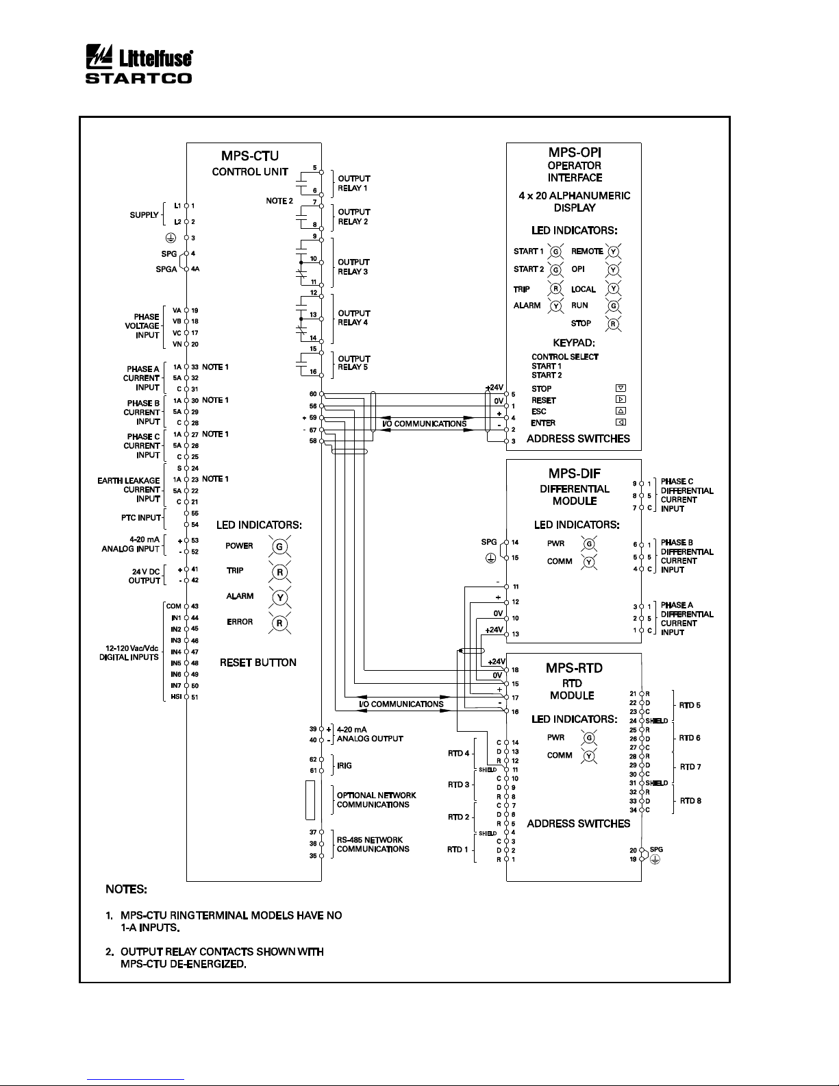
The Littelfuse Startco Motor Protection System (MPS)
is a modular system with integrated protection, control,
metering, and data-logging functions. The Control Unit
(MPS-CTU) is the core module. It can operate as a stand-
alone unit or with the Operator Interface (MPS-OPI),
RTD Modules (MPS-RTD), and Differential Module
(MPS-DIF). The CTU can be programmed using the OPI
or the communications network. Programmable inputs
and outputs provide a flexible hardware platform and
custom software can be easily loaded from a PC to the
CTU’s flash memory. The MPS block diagram is shown
in Fig. 1.1.
1.2 MPS FEATURES
1.2.1 PROTECTION
•Overload (49, 51)
•Overcurrent (50, 51)
•Earth fault (50G/N, 51G/N)
•Unbalance (voltage and current) (46, 47)
•Phase loss (voltage and current) (46, 47)
•Phase reverse (voltage and current) (46, 47)
•Jam
•Undercurrent (37)
•Failure to accelerate
•Underspeed (14)
•Overvoltage (59)
•Undervoltage (27)
•Underpower (37)
•Reversepower (32)
•Power factor (55)
•Overfrequency (81)
•Underfrequency (81)
•PTC overtemperature (49)
•RTD temperature (38, 49)
•Starts per Hour (66)
•Differential (87)
1.2.2 CONTROL—STARTING METHODS (1)
•Non-reversing
•Reversing
•Soft start
•Soft start with bypass
•Adjustable-speed drive
•Two speed
•Wye-delta (open or closed transition)
•Reactor (open or closed transition)
•Resistor (open or closed transition)
•Autotransformer
•Part winding
•Slip ring
•Two winding
•Double delta
(1) Only three CT’s required for all starting methods.
1.2.3 METERING
•Line currents
•Current unbalance
•Positive-sequence current
•Negative-sequence current
•Earth-leakage current
•Differential currents
•Line-to-line voltages
•Line frequency
•Voltage unbalance
•Positive-sequence voltage
•Negative-sequence voltage
•Power
§Apparent, Reactive, Real, and Power factor
•Energy
§kWh, kVAh, and kVARh
•Used thermal capacity
•Thermal trend
•Motor speed
•RTD temperatures
•Analog input and output
1.2.4 DATA LOGGING
•Sixty-four records
§Date and time of event
§Event type
§Line currents
§Current unbalance
§Earth-leakage current
§Differential currents
§Line-to-line voltages
§Voltage unbalance
§Thermal capacity
§Thermal capacity used during starts
§Start time
§Analog-input value
§Frequency
§Power (P, S, Q, PF)
§RTD temperatures
§Trip counters
§Running hours
§Waveform Capture
§5 seconds of pre-trip waveform data
§16 samples per cycle
§COMTRADE and CSV file generation
1.2.5 INPUTS AND OUTPUTS
•Three ac-current inputs
•Three ac-voltage inputs
•Earth-leakage-current input
•Seven programmable digital (ac/dc) inputs
•24-Vdc source for digital inputs
•Tachometer (high-speed pulse) input
•4-20-mA analog input
•4-20-mA analog output
•PTC thermistor temperature input

Page 1-2
MPS Motor Protection System Rev. 6-F-022117
Introduction
•Up to twenty-four RTD inputs
•Five programmable output relays
•Network communications
•IRIG-B time-code input
1.2.6 MPS-OPI OPERATOR INTERFACE
•4 x 20 vacuum-fluorescent display
•Starter-control keys
•Display-control and programming keys
•LED status indication
•Remote operation up to 1.2 km (4,000’)
•Powered by MPS-CTU
1.2.7 MPS-RTD MODULE
•Eight inputs per module
•Individually selectable RTD types
•RTD Voting
•Solid-state multiplexing
•Up to three modules per system
•Remote operation up to 1.2 km (4,000’)
•Powered by MPS-CTU
1.2.8 MPS-DIF DIFFERENTIAL MODULE
•3-CT core-balance connection
•6-CT summation connection
•Remote operation up to 1.2 km (4,000’)
•Powered by MPS-CTU
1.2.9 COMMUNICATIONS INTERFACE
The standard network communication interface is an
RS-485 port with Modbus®RTU and A-B®DF1 protocol
support. In addition to the standard interface, network
communication options include DeviceNet™, Profibus®,
Modbus®TCP, and Ethernet/IP.
1.3 ORDERING INFORMATION
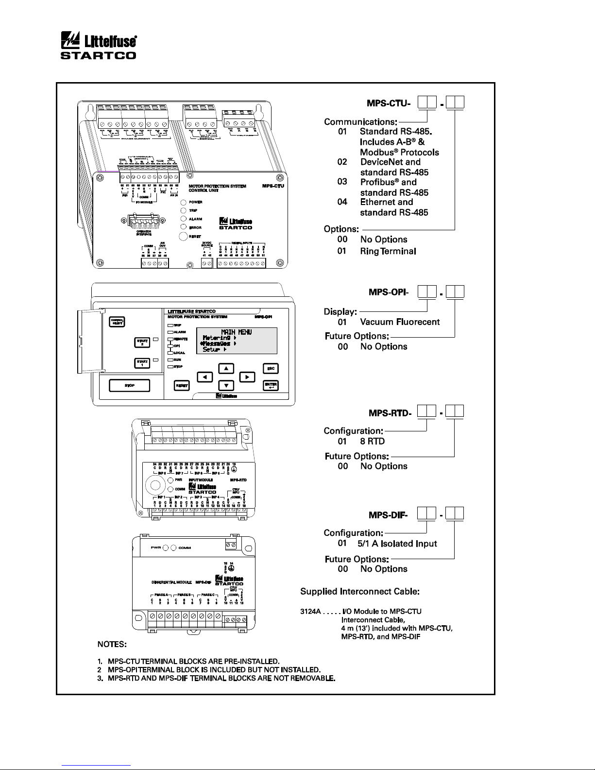
See Fig. 1.2 for MPS-CTU, MPS-OPI, MPS-RTD, and
MPS-DIF model numbers.
Earth-Fault Current Sensors:
EFCT-1 ......................... Earth-Fault CT,
5-A-primary rating,
82 mm (3.2”) window
EFCT-1FC..................... Flux Conditioner for EFCT-1,
70 mm (2.7”) window
EFCT-2 ......................... Earth-Fault CT with
Flux Conditioner,
5-A-primary rating,
139 mm (5.5”) window
EFCT-26 .......................Earth-Fault CT,
5-A-primary rating,
26 mm (1”) window
(All EFCT’s include 6 m (19.5’) of 22 AWG (0.33 mm2)
shielded cable.)
SE-CS30-4 ............................. Current Sensor,
30-A-primary rating,
c/w Flux Conditioner,
95.0 mm (3.7”) window
SE-CS30-5 ............................. Current Sensor,
30-A-primary rating,
c/w Flux Conditioner,
130.0 mm (5.1”) window
SE-CS30-8 ............................. Current Sensor
30-A-primary rating,
c/w Flux Conditioner,
200.0 mm (7.9”) window
SE-CS30-26......................... Current Sensor,
30-A-primary rating,
26 mm (1.0”) window
SE-CS30-70......................... Current Sensor,
30-A-primary rating,
70 mm (2.7”) window
Phase CT’s............................... Protection-Class CT’s,
Contact factory
Accessories:
SE-IP65CVR-M................... Hinged Transparent OPI
Cover
SE-485-PP............................ Port-Powered Serial
Converter
SE-485-DIN ......................... Serial Converter,
Industrial, 24 Vdc
Software:
SE-Comm-RIS ..................... PC Communication
Software(1)
SE-Flash............................... Firmware Upgrade
Software(1)
(1) Available at www.littelfuse.com/relayscontrols.
Page 1-3
MPS Motor Protection System Rev. 6-F-022117
Introduction
FIGURE 1.1 Motor Protection System Block Diagram.
Page 1-4
MPS Motor Protection System Rev. 6-F-022117
Introduction
FIGURE 1.2 MPS Ordering Information.

Page 2-1
MPS Motor Protection System Rev. 6-F-022117
Installation
2. INSTALLATION
2.1 GENERAL
A basic Motor Protection System (MPS) consists of an
MPS-CTU and three customer-supplied current
transformers (CT's) for measuring phase current. For
core-balance earth-fault detection, a 1-A, 5-A, EFCT-1, or
EFCT-2 CT is required. For the optional Ring Terminal
MPS-CTU, the 1-A connection is not available. The
residual phase-CT connection can also be used for earth-
fault detection. Voltage inputs do not require potential
transformers (PT’s) for system voltages up to 600 Vac.
For RTD-temperature measurement, up to three
MPS-RTD modules can be connected to the MPS-CTU.
For differential protection, an MPS-DIF module can be
connected to the MPS-CTU. The MPS-OPI provides an
operator interface for the MPS.
The MPS power-factor-corrected switch-mode power
supply is rated 65 to 265 Vac and 80 to 275 Vdc.
All modules can be mounted in any orientation.
2.2 MPS-CTU CONTROL UNIT
The Control Unit is configured for surface mounting.
Outline and mounting details for the MPS-CTU are
shown in Figs. 2.1 and 2.1.1.
2.3 MPS-OPI OPERATOR INTERFACE
Outline and mounting details for the MPS-OPI are
shown in Fig. 2.2. It is certified for use in Class I, Zone 2
and Class I, Division 2 hazardous locations.
The Operator Interface is configured for panel
mounting or it can be mounted on the MPS-CTU as
shown in Fig. 2.3. The Operator Interface can also be
mounted on the MPS-CTU ring terminal as shown in
Fig. 2.3.1 (surface mount only).
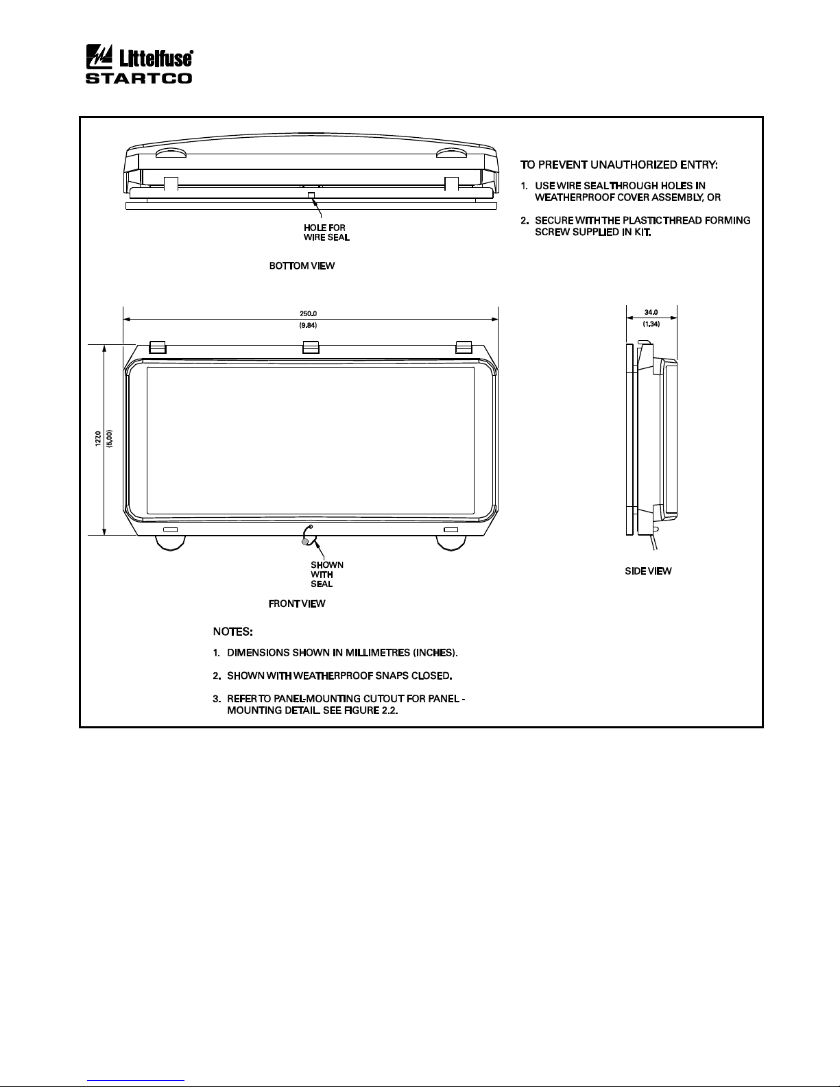
If an optional SE-IP65CVR-M is used, follow the
included installation instructions. See Figs. 2.4 and 2.5.
2.4 MPS-RTD MODULE
Outline and mounting details for the MPS-RTD are
shown in Fig. 2.6. The MPS-RTD will fit inside most
motor RTD-termination junction boxes and it is certified
for use in Class I, Zone 2 and Class I, Division 2
hazardous locations. The MPS-RTD can be surface or
DIN-rail mounted.
2.5 MPS-DIF DIFFERENTIAL MODULE
Outline and mounting details for the MPS-DIF are
shown in Fig 2.7. The MPS-DIF can be surface or DIN-
rail mounted.
2.6 EARTH-FAULT CT’S
Outline and mounting details for the EFCT-1, EFCT-2,
EFCT-26, and SE-CS30 series are shown in Figs. 2.8, 2.9,
2.10, 2.11, and 2.12.

Page 2-2
MPS Motor Protection System Rev. 6-F-022117
Installation
FIGURE 2.1MPS-CTU Outline and Mounting Details.

Page 2-3
MPS Motor Protection System Rev. 6-F-022117
Installation
FIGURE 2.1.1 MPS-CTU-XX-X1 Ring Terminal Outline and Mounting Details.

Page 2-4
MPS Motor Protection System Rev. 6-F-022117
Installation
FIGURE 2.2 MPS-OPI Outline and Mounting Details.

Page 2-5
MPS Motor Protection System Rev. 6-F-022117
Installation
FIGURE 2.3 MPS-CTU with OPI Outline and Mounting Details.

Page 2-6
MPS Motor Protection System Rev. 6-F-022117
Installation
FIGURE 2.3.1 MPS-CTU Ring Terminal with OPI Outline and Mounting Details.
Page 2-7
MPS Motor Protection System Rev. 6-F-022117
Installation
FIGURE 2.4 SE-IP65CVR-M Weatherproof Cover Outline.

Page 2-8
MPS Motor Protection System Rev. 6-F-022117
Installation
FIGURE 2.5 SE-IP65CVR-M Weatherproof Cover Installation.

Page 2-9
MPS Motor Protection System Rev. 6-F-022117
Installation
FIGURE 2.6MPS-RTD Outline and Mounting Details.

Page 2-10
MPS Motor Protection System Rev. 6-F-022117
Installation
FIGURE 2.7MPS-DIF Outline and Mounting Details.
Table of contents


