10
5.8 Connection Diagrams
5.
8.1
RELAY
CONNECTIONS
A simple block diagram
is
provided in Fig.
11
to illus-
trate the internal functional circuits
of
the type GFR
Relay. Complete external connections are a function
of
the associated devices used with the relay along with the
complexity
of
the system in which the components are
applied. The terminals on the
GFR
relay are suitable for
#18 through
#14
AWG
copper conductors. A maximum
of
two per terminal are permitted.
5.8.2 TYPICAL SYSTEMDIAGRAMS
Basic, typical radial distribution system diagrams are pro-
vided
in
this leaflet for guidance; refer to Figs. l
lA,
118,
llC,
llDand
llE.
Two multiple source distribution systems are illus-
trated in Figs.
11
F and l
lH.
Fig.
11
F illustrates a dual
source distribution system with center point grounding
as
allowed in the National Electrical Code under Article
250-23a, Exception No. 4 Fig.
11
H illustrates a multiple
source, multiple ground distribution system with zone dif-
ferential ground fault sensing methods employed.
5.8.3 ZONE DIFFERENTIAL GFR OPERATION
PRINCIPLES -SEE
FIG.
l JH
5.8.3.1 In general,
G~~
will operate only for ground
faults within Zone 1 and
G~~
for Zone 2. This includes
ground faults for feeders located in these respective zones.
5.8.3.2 With
"Ml"
and
"T"
closed and "M2" open and
with a ground fault in Zone
2,
G~~
will not operate
to
trip
"Ml"
but,
G:~
will
to
trip
"T".
5.8.3.3 Conversely, with "M2" and
"T"
closed and
"Ml"
open and with a ground fault in Zone 1,
G:~
will not op-
.
"M2"
b GFR
·11
.
"T"
erate
to
tnp
ut
M2
w1
to
tnp
.
5.8.3.4 For properly co-ordinated main, tie and feeder
interrupting devices, the feeder relays will always react
to clear a downstream ground fault prior
to
operation
of
either the main or tie devices.
5.8.3.5 Zone interlock wiring between upstream and
downstream devices can be included
as
shown. For this
scheme, no cross interlocking with
"T"
auxiliary contacts
is
required.
5.8.3.6 This scheme may be expanded to additional alter-
nate sources
as
long
as
interrupting devices are available
to
isolate any potential ground fault on each side
of
the
fault.
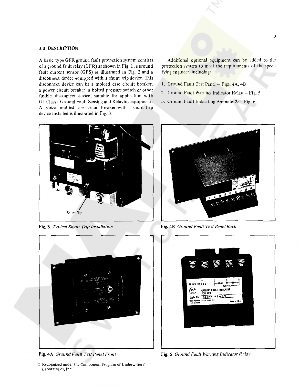
6.0
GROUND FAULT CURRENT SENSORS
(See Table 6, Page 24)
6
.1
General Description
As
indicated in Table 6 (Page 24), Ground Fault Current
Sensors (GFS) are available in a variety
of
physical sizes
and current ratings to match the application requirements
of
the distribution system. Sensors should be selected to
match the ampere rating
of
the specified
GFR
Relay. The
physical size should be selected to properly encompass the
required conductor configuration with space allowed for
minimum clearances
as
shown
in
the applicable outline
mounting figure. Outline references
are
given
in
Table 6.
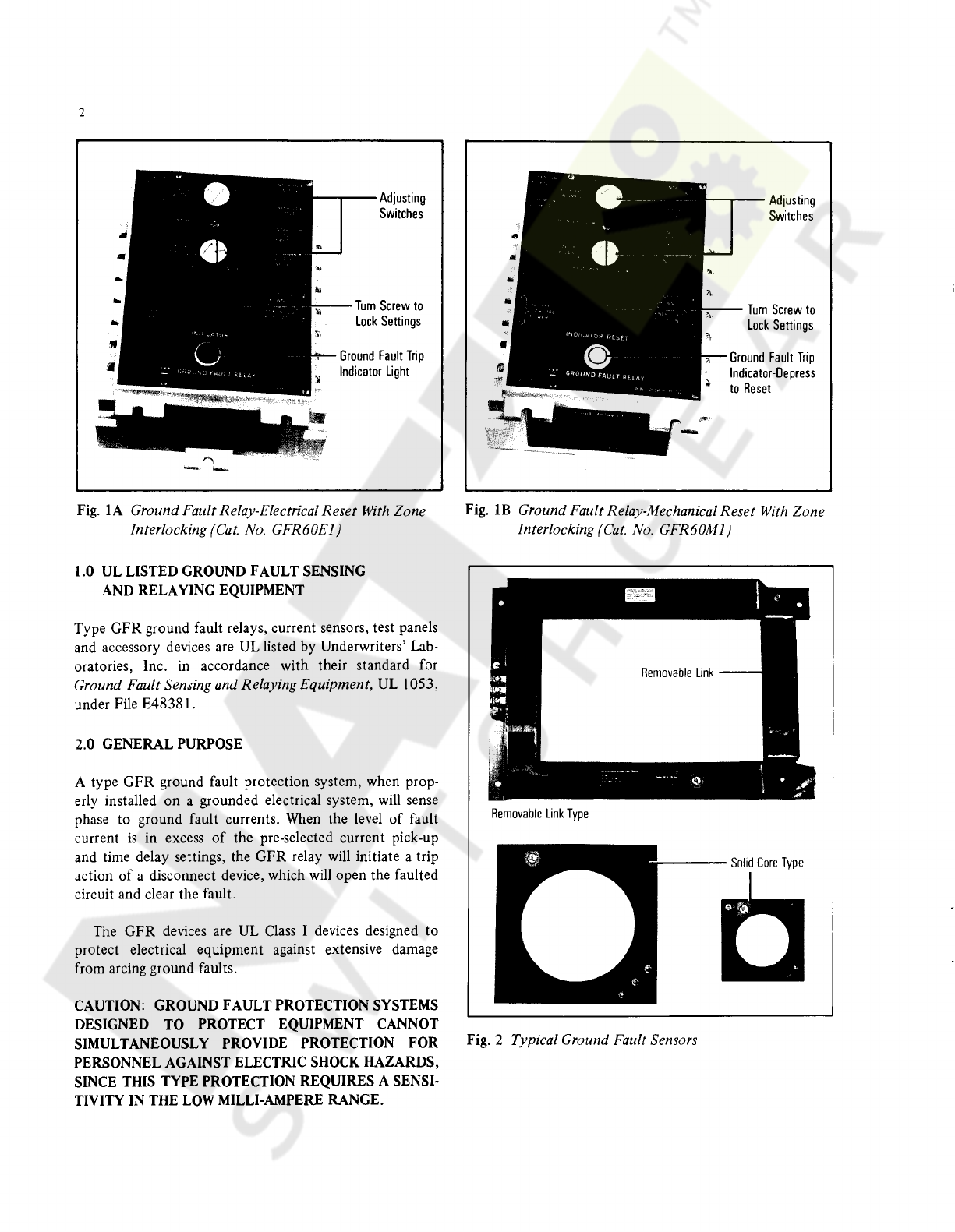
Sensors are available with solid cores having round con-
ductor openings and in split core designs with various size
rectangular openings. On the split core designs, one core
leg
is
removable
to
permit ease
of
installation around
existing conductor assemblies.
Ground Fault Current Sensors are special rated current
transformers and must be applied only with type GFR
Relays shown in Table
1.
Sensors cannot be used with any
other equipment.
Sensors are insulated with cast apoxy and can be
mounted directly to enclosure surfaces. Ideally, they
should be installed
so
that all conductors passing through
the sensor opening are physically centered in the window
opening. Minimum clearances are specified in the applica-
ble outline,
but
greater clearances will help reduce any
possible error signals. Rectangular configurations are pro-
vided with compensating windings to reduce potential
error signals.
All
sensors are provided with integral test winding for
use under simulated ground fault test conditions. With
an input
of
1.2 Amps into terminals 2-3, a rated
output
of
240 M.A. should be produced in terminals
1-3
with a
tolerance
of
±15%. For information purposes, the turns
ra-
tio and saturation levels
of
all sensors
is
provided
in
Table 6.
Courtesy of NationalSwitchgear.com