LiveU LU200 User Guide
6
Appendix B: Limitation of Liability and Warranty ................................................. 67
Limitation of Liability and Warranty ...........................................................................67
Appendix C: FCC Compliance.............................................................................. 69
Table of Figures
Figure 1: LU200 – Front Panel...........................................................................................................................9
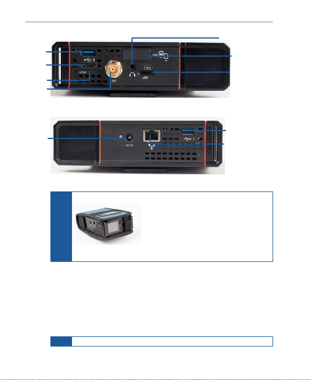
Figure 2: LU200 – Right Side Panel................................................................................................................10
Figure 3: LU200 – Left Side Panel ..................................................................................................................10
Figure 4: LU200 Inside Its Pouch....................................................................................................................10
Figure 5: Solution Architecture......................................................................................................................11
Figure 6: LU200 Joystick..................................................................................................................................12
Figure 7: LiveU Central...................................................................................................................................13
Figure 8: LU200 Remote Control Screen......................................................................................................13
Figure 9: LU200 Camera Connections.........................................................................................................16
Figure 10: LU200 Camera Mount..................................................................................................................16
Figure 11: Opening the Screws on the Camera Mount Adapter...........................................................17
Figure 12: Tightening the Top Screw on the Camera Mount Adapter...................................................17
Figure 13: Tightening the Bottom Screw on the Camera Mount Adapter............................................17
Figure 14: DC IN Connection........................................................................................................................18
Figure 15: Power Switch.................................................................................................................................19
Figure 16: LU200 Home Screen – Offline and Ready States.....................................................................19
Figure 17: Battery Status Icon - Main Screen..............................................................................................20
Figure 18: LU200 Home Screen – While Streaming ....................................................................................21
Figure 19: Channels Screen...........................................................................................................................22
Figure 20: LU200 Micro SD Card Slot ............................................................................................................24
Figure 21: Main Screen −Profile ...................................................................................................................25
Figure 22: Profiles Screen...............................................................................................................................25
Figure 23: Main Screen −Delay....................................................................................................................26
Figure 24: Delay Screen.................................................................................................................................26
Figure 25: Interfaces Screen..........................................................................................................................27
Figure 26: Main Screen − Interfaces ............................................................................................................30
Figure 27: Interfaces Screen..........................................................................................................................30
Figure 28: Disable Interface – 1 ....................................................................................................................30
Figure 29: Disable Interface – 2 ....................................................................................................................31
Figure 30: Main Screen − Interfaces ............................................................................................................31
Figure 31: Interfaces Screen..........................................................................................................................31
Figure 32: Enable Interface...........................................................................................................................32
Figure 33: Select Network..............................................................................................................................32
Figure 34: Select Network..............................................................................................................................33
Figure 35: WiFi Network – Connect..............................................................................................................33
Figure 36: Virtual Keyboard...........................................................................................................................33
Figure 37: Main Screen ..................................................................................................................................34