LIXIL ORP-R! Instructions for use

· Constructing the product may be dangerous. Be sure to have a professional contractor construct the product.
· This product is a simplified carport. Do not carelessly modify or rebuild the product in order to convert it into storage space,
playing space or residential space.
· Do not construct the product in a place where snowfall (fresh snow) of more than
20 cm may happen.
· Place the product where snow will not slide off the roof of the house directly onto
the product.
· Do not construct the product on a cliff, a roof or in any other place with strong
winds.
· Do not construct the product in a place where waste heat from a hot-water heater or a heating apparatus will build up inside the
product. Toxicosis may occur due to exhaust.
· If constructing the product on a slope, ensure sufficient embedding depth on the lower side.
· If constructing products of different sizes simultaneously in the same place, be sure not to mix components of each
product in order to preserve the original performance.
· Be sure to read this construction manual before construction for proper construction and assembly.
· Be sure to construct the product by following this construction manual.
· Check if all the required components and parts are provided by referring to the package details.
· Make sure that the product is constructed where waste heat from a hot-water heater or a heating apparatus will not contact the
product. Coating deterioration / exfoliation may occur due to exhaust.
· Check if the product properly fits the size of the construction place.
<Before Construction>
Warning
Caution
· Helpful tips complementing construction instructions.
· Matters you should take particular care with during the construction process.
· If not followed, construction will fail or failure may occur after the product is constructed.
· Matters to be noted related to the contents of construction instructions (each instruction).
· Conditions where limitations apply to construction instructions.
*
Tip
· Thank you for purchasing our product.
· The indication symbols in this construction manual are for you to construct the product safely and properly and also to
protect the owner etc. from damage.
Be sure to understand the meaning of each indication symbol and act in accordance with this manual (its instructions).
* Observe the following items to prevent personal injury or property damage due to damage or
collapse of the product.
· If not followed, the user may suffer a minor / moderate injury or property damage may occur.
Warning
Caution
In this construction manual, the following symbols are used.
ORP-R1
Wide: Basic / J-Connection Construction Manual
D637
-1-

· If substances such as mortar or concrete have adhered to the product surface, quickly wipe them away.
Otherwise the product appearance may be affected with stains or blotches.
Caution
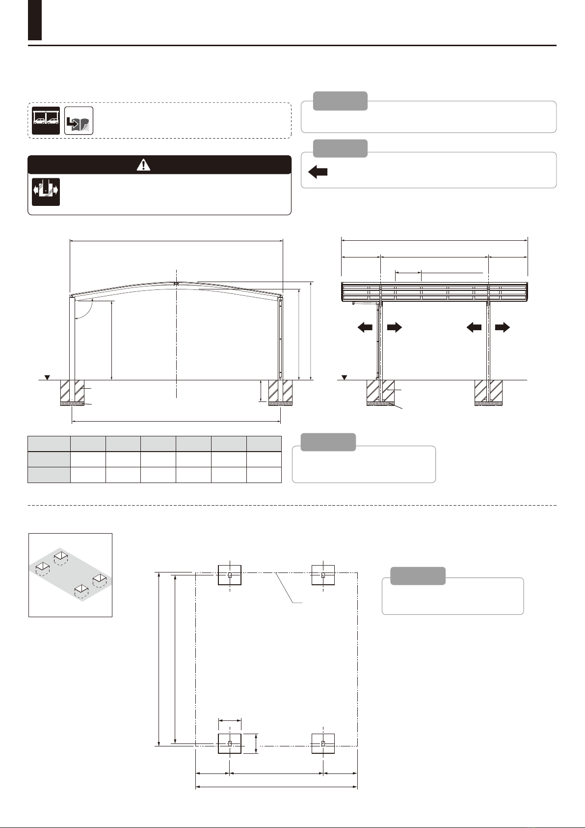
<About Foundation Construction>
· For cold places where the subsoil may be frozen, build the foundations deeper than the frost line. Otherwise, strength degradation
may occur.
· Be sure to lay crushed stones on the foundations and make water draining holes (I6) at the base of the pillars and foundations for
water drainage inside the pillars.
Otherwise the water inside the pillars may freeze and expand, causing damage to the pillars.
· Do not apply sand containing salt (sea sand) or chlorine-based strongly alkaline concrete admixtures (anti-freezing agents, curing
accelerators, accelerators, etc.) to mortar or concrete.
Otherwise, metal such as aluminum may be corroded. If required, use chlorine-free or non-alkaline admixtures.
Warning
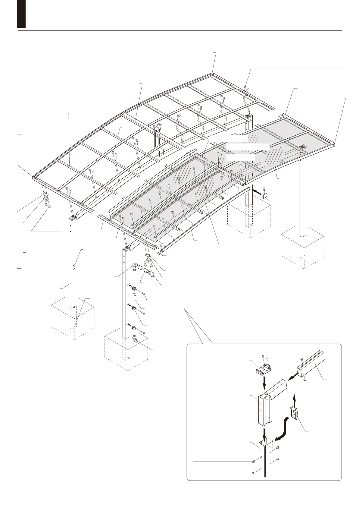
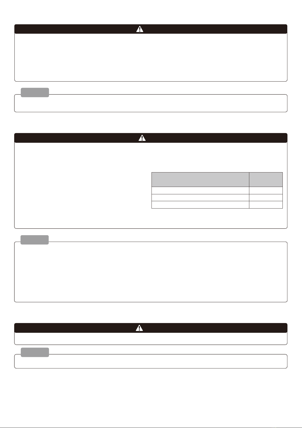
* I4 Screws: 2.5 N ∙ m ± 0.5 N ∙ m (25 ± 5 kgf ∙ cm)
* I5 Screws: 3.0 N ∙ m ± 0.5 N ∙ m (30 ± 5 kgf ∙ cm)
* M8 Bolts: 20.0 N ∙ m ± 0.5 N ∙ m (200 ± 5 kgf ∙ cm)
Product Name
and Number
Sealant 72
TOSSEAL 380
SE960
Sealant Manufacturer
Shin-Etsu Chemical Co., Ltd.
Momentive Performance Materials Japan LLC
Toray / Dow Corning Corporation
<Warnings During Construction>
<After Construction>
· Give the installation manual to the owner.
Caution
Caution
· If a water pipe is mounted to the pillar labeled "Warnings for Use", it will hide the label and the warnings will not be provided
properly. Use on the side where water pipes are not mounted.
· If aluminum products contact metal other than zinc or stainless steel, implement insulation.
· Do not modify the product or make holes other than on the specified points.
· Seal the specified points in order to prevent water leakage.
· If using silicone sealant, use our specified dealcoholized
sealant in order to avoid failure such as cracks in
polycarbonate boards.
· In order to prevent product strength degradation or injury,
use the specified number of our genuine bolts and screws
and make sure that there is no looseness after fixing them
at the following recommended torque.
· Retighten the bolts and nuts.
· Work safely during construction.
* Wear working clothes properly (safety helmets, safety belts and protective equipment for eyes, hands and feet) .
* Keep the workplace tidy and ensure safety.
Ensuring safety for high place work, preventing collapse, keeping enough illuminance with lighting, etc. are especially important.
* Check the functions of equipment, tools, protective equipment, etc. before using them.
* Consider each work and process while proceeding with construction. Work which requires a license, skill training or special
education must only be done by a qualified person.
* Workers should confirm one another's safety. Be sure to check the health of each worker and maintain health management.
* If an accident should happen, immediately provide first aid and prioritize rescue over anything else.
· Remove stains on the product surface. If the product surface is damaged by mistake, repair it with repairing coating.
Warning
Warning
-2-

Construction Process
Indication Symbols ............................................... 3
Construction Process ........................................... 3
Package Details .................................................... 4
Part Names ........................................................... 6
Construction of Basic Type .................................. 7
Basic Items to Check .................................. 7
1
Checking Foundation Dimensions .............. 8
2
Preparation for Pillar Construction ............. 9
3
Constructing Pillars and Beams ................. 9
4
Processing Components .......................... 10
5
Mounting Rear Frames /
Roof Purlins / Wide Ridgepoles ................ 11
6
Mounting Side Frames .............................. 12
7
Checking Diagonal Dimensions ................ 14
8
Mounting Roof Rafters .............................. 14
9
Mounting PC Roof Panels ........................ 15
10
Mounting Side Frame Covers / Roof Rafter Covers
... 16
11
Mounting Water Pipes .............................. 17
Construction of J-Connection Type ................... 18
Items to Check for J-Connection ............. 18
1
Processing Connection Part ..................... 19
2
Connecting Connection Part .................... 20
INDEX
Indication Symbols
Independent
Foundations
For Construction
with Independent Foundations
For Construction
with Concrete Slabs on Grade
Concrete Slabs
on Grade
For Construction
by Moving Pillar Position
Pillar Moving
For Constructing
"J-Connection"
J-Connection
Optional
Product
Sealing
Point
Optional
Sealing
1
Marking Foundation Position
2
Preparation for Pillar Construction
3
Mounting Brackets and Beams
4
5
6
7Mounting Side Frames 8Checking Diagonals
9Mounting Roof Rafters
10
Mounting PC Roof Panels
11
12
Mounting Water Pipes
Mounting Caps and
Pillar-Beam Covers
Mounting Rear Frames /
Roof Purlins / Wide Ridgepoles
Mounting Front /
Rear Frame Corner Caps
Mounting Side Frame Covers /
Roof Rafter Covers
-3-

Package Details *
Check if all the required components and parts are provided by referring to the package details.
[2] Bracket Set Required Quantity
Name Sketch 2 Included
Bracket 2
[4] Length Set Required Quantity
Name Sketch W48 / 54
L50
Rear Frame 1
Roof Purlin 3
Water Pipe I40
L = 3500 1
[5] Wide Ridgepole Set Required Quantity
Name Sketch 1 Included
Wide Ridgepole 1
[6] Width Set Required Quantity
Name Sketch L50
Side Frame 1 Each for Right and Left
Side Frame Cover
2
Roof Rafter 6
Roof Rafter
Cover 6
[8] Parts Set Required Quantity
Name Sketch W48 / 54
L50
Rear Frame Corner Cap R 2
Rear Frame Corner Cap L 2
Wide Ridgepole Cap 2
Wide Ridgepole
Mounting Bracket 2
Pillar Cap 4
Pillar-Beam Cover 4
Anchor Stick I8 x 200 4
Hole Hiding Sticker I10 40
Rainwater Pipe Attachment
2
Rainwater Pipe Hole
Cover Cap 2
Rainwater Pipe Packing 4
Drain Elbow for I40 2
92° Elbow I40 4
Rainwater Pipe Holder 6
Adhesive 1
Panel Cushion 48
[8-1]
M8 x 20 Hex Bolt
(with Plain Washer and Loosening Prevention)
24
[8-2] I5 x 12
Self-Tapping Truss Head Screw Class 3
296
[8-3]
I4 x 13 Pan Head Self Drilling Screw
6
Construction Manual (D621)
-1
Installation Manual (UD127)
-1
[1] Pillar Set Required Quantity
Name Sketch 2 Included
Pillar 2
[3] Beam Set Required Quantity
Name Sketch 2 Included
Beam 2
[7] PC Roof Panel Set Required Quantity
Name Sketch 3 Included 4 Included
Roof 34
-4-

[9] Water Pipe Set Required Quantity
Name Sketch L = 3100
Water Pipe I40 1
[10]
Connection Component Set
Required Quantity
Name Sketch W48 / 54
Wide Ridgepole
Sleeve 1
Rear Frame Sleeve 2
Roof Purlin Sleeve 6
Wide Ridgepole
Water Stop Packing
1
[10-1] I4 x 13
Pan Head Self Drilling Screw
88
[11]
Connection Width Set
Required Quantity
Name Sketch L50
Roof Rafter 7
Roof Rafter Cover 7
[12]
PC Roof Panel Holder Set
Optional Required Quantity
Name Sketch L50
Panel Stopper 7
PC Roof Panel Holder
Spacer 4
[12-1] I5 x 13
Pan Head Self Drilling Screw
26
PC Roof Panel Holder
Mounting Manual (D614)
- 1
Optional
Optional
-5-

Wide Ridgepole
Side Frame Cover
Roof Purlin
Panel Cushion
Rear Frame Corner
Cap (R)
[Part Number]
629879
Rear Frame Corner
Cap (R)
[Part Number]
629879
Side
Frame
Side
Frame
Wide
Ridgepole
Cap
Attachment Packing
Attachment
Packing
Rainwater Pipe Attachment
Drain Elbow
Water Pipe
Water Pipe
Rainwater
Pipe Holder
92°
Elbow
92°
Elbow
"Warnings for Use"
Label
Anchor Stick
Rear Frame
Pillar
Rear Frame
Rainwater Pipe Hole
Cover Cap
[8-2]
I5 x 12
Self-Tapping Truss Head
Screw Class 3
Part Names
PC Roof Panel
Roof Rafter
[8-2] I5 x 12
Self-Tapping Truss Head Screw Class 3
[8-3] I4 x 13
Pan Head Self Drilling Screw
Rear Frame Corner Cap (L)
[Part Number] 629878
Rear Frame Corner Cap (L)
[Part Number] 629878
PC Roof Panel Receiver
Beam
Pillar-Beam
Cover
Bracket
Pillar
Pillar Cap
[8-1] M8 x 20
Hex Bolt
(with Plain Washer and Loosening Prevention)
Roof Rafter Cover
-6-

Foundation Concrete
Crushed Stones
4980
1040 2900 [Pillar Core-to-Core] 1040
Construction of Basic Type
100100100100
H2
500
H1
H
T°
Basic Items to Check
W1
W2 [Pillar Core-to-Core]
Foundation Concrete
Crushed Stones
GLGL
Tip
This symbol indicates the [Pillar Moving] range.
Drawing
Warning
For [Pillar Moving],
move the pillar within ±100 mm of the pillar core-to-core
distance dimensions.
Pillar Moving
Tip
Refer to page 8 for foundation
dimensions (DW / DL).
Marking Foundations
· Be sure to lay crushed stones so that the water inside the pillars can be drained.
Caution
(1) Determine the embedding position for pillars and then dig foundation holes.
Tip
Add 364 to the height dimension.
[For Long Pillars]
Size (Width)
W1 W2 H1
W48 4836 4704 2276
W54 5442 5310 2324
H
1844
1844
H2
2100
2148
T
99
99
For the foundation dimensions of [J-Connection], also
refer to page 18.
P.18
J-Connection
706 [Roof Rafter Core-to-Core]
L1
L2 [Pillar Core-to-Core]
Carport Main Unit
Outer Line
L3
DL
L3
W2 [Pillar Core-to-Core]
W1
DW
-7-

Pillar
50
500
100
DL
DW
50
50
(1) Check the foundation hole dimensions.
Lay rebar.
Caution
Foundation Concrete
Crushed Stones
Pillar
200 or More
Concrete Slabs
on Grade
Rebar
100 or More
Work required for [Construction with Concrete Slabs on Grade].
Concrete Slabs
on Grade
Work required for [Construction with Independent Foundations].
Independent
Foundations
Caution
Also refer to the foundation dimensions on this page for [J-Connection].
J-Connection
GL
The edge distance between the top of the foundation and
the concrete slabs on grade must be 200 mm or more.
Rear Frame Side
Ridgepole Side
Rear Frame Side
Ridgepole Side
(*1) is the dimension between the pillar core and the
foundation edge on the rear side of the foundation.
Tip
Pillar
DL
DW
300
(* 1)
500
Size (Width) DW
W48 700
W54 700
DL
600
600
* The DL center position is the pillar core.
Size (Width) DW
W48 400
W54 400
DL
300
300
* The DL center position is the pillar core.
1Checking Foundation Dimensions
-8-

Caution
Check if the pillar is vertical.
Construct the pillar
so that the
"Warnings for Use"
label will not be
hidden by the water
pipe.
Caution
[When Constructing Pillars]
Caution
(1) Insert an anchor stick to the pillar.
(2) Make a I6 water drain hole near the G.L. of the pillar (aboveground).
Level
Pillar
15
I6
Water Drain Hole
GL
Foundation Stone
Direct the notches on
the pillar to the inside.
Caution
Pillar Inside
1Mounting Brackets and Beams
(1) Insert a bracket to the pillar and mount it with [8-1].
(2) Mount a beam to the bracket with [8-1].
[8-1] M8 x 20
Hex Bolt
(with Plain Washer and Loosening Prevention)
Bracket
Beam
Pillar
[8-1] M8 x 20
Hex Bolt
(with Plain Washer and
Loosening Prevention)
Bracket
Anchor Stick
Caution
Check the diagonal dimensions between the pillars before fixing them.
Warning
The pillar may be damaged if
there is no water drain hole.
Do not "loosen or tighten" bolts after the loosening prevention
agent has cured. Bolts may become easy to loosen.
(Cures in about 24 hours after tightening.
2Preparation for Pillar Construction
3Constructing Pillars and Beams
-9-

[8-2] I5 x 12
Self-Tapping Truss Head Screw Class 3
Pillar-Beam Cover
Spread
Pillar Cap
Pillar
(1) Put a pillar cap on the pillar.
(2) Fit a pillar-beam cover into the notch on the pillar.
(3) Mount the pillar-beam cover to the pillar cap with [8-2].
Beam
(1) Process holes on the component.
(2) Cover the existing holes with hole hiding stickers.
For Pillar Moving
(processing components to be mounted on moved pillars or beams)
Pillar Moving Distance
I5.5 Processed Hole
I5.5 Processed Hole
I5.5
Processed
Hole
I4.5 Processed Hole
[Rear Frame]
[Rear Frame]
[Roof Purlin]
[Roof Purlin]
[Wide Ridgepole]
[Wide Ridgepole]
36
36
18
36
Work required for
[Pillar Moving].
Pillar Moving
Spread
Rotate
Hook
[8-2] I5 x 12
Self-Tapping Truss Head
Screw Class 3
Press them together
Pillar-Beam Cover
Pillar Cap
Pillar Moving Distance
I5.5 Additionally
Processed Hole
Hole Hiding
Stickers
Existing Hole
Pillar Moving Distance
Wide Ridgepole
(Bottom Surface)
Press them together
During this step, pillar caps or pillar-beam
covers are slightly unsteady.
Tip
2Mounting Caps / Pillar-Beam Covers
4Processing Components
-10-

[8-2] I5 x 12
Self-Tapping Truss Head
Screw Class 3
[8-2] I5 x 12
Self-Tapping Truss Head
Screw Class 3
Panel Cushion
Bracket
Rear Frame
PC Roof
Panel Receiver
Panel Cushion
1 Mounting Rear Frames / Roof Purlins
(1) Mount a rear frame to the bracket with [8-2].
(2) Affix a panel cushion to the roof purlin.
(3) Mount the roof purlin to the beam with [8-2].
Between Holes
Roof Purlin Center
Between Holes
Affix the panel cushion to the position shown
in the figure below.
Panel
Cushion
Caution
Between Notches
Center
Move the PC roof panel receiver to the position
shown in the figure below.
Caution
Fin
Beam
Rear Frame Side
Wide Ridgepole Side
Caution
Page 19 / 20
For [J-Connection], also refer to page
19 / 20 prior to work.
J-Connection
Direct the fin on
the roof purlin to
the wide ridgepole
side.
5Mounting Rear Frames / Roof Purlins / Wide Ridgepoles
-11-

2 Mounting Wide Ridgepoles
(1) Mount a wide ridgepole mounting bracket to the bottom surface of the wide ridgepole with [8-2].
(2) Mount the wide ridgepole to the beam with [8-2].
Wide Ridgepole
Wide Ridgepole
(Bottom Surface)
Wide Ridgepole
Mounting Bracket
Beam
[8-2] I5 x 12
Self-Tapping Truss
Head Screw Class 3
[8-2] I5 x 12
Self-Tapping
Truss Head Screw Class 3
Turn Over
[View from Bottom]
Page 19 / 20
For [J-Connection], also refer to page
19 / 20 prior to work.
J-Connection
(1) Fill a rear frame corner cap with sealant.
(2) Put the rear frame corner cap on the side frame.
1 Mounting Rear Frame Corner Caps
Side Frame
Rear Frame Corner Cap (R)
[Part Number] 629879
Rear Frame
Insertion
Surface
Side Frame
Insertion
Surface
Sealing
6Mounting Side Frames
-12-

(1) Mount a wide ridgepole cap on the wide ridgepole.
(2) Fill the wide ridgepole cap with sealant.
(3) Mount side frames to the rear frame / roof purlin / wide ridgepole with [8-2].
2 Mounting Side Frames
Side
Frame
Rear Frame
Side Frame
Roof
Purlin
Side Frame
Side Frame
Side
Frame
Side Frame
Rear Frame
Roof Purlin
Wide
Ridgepole
[8-2] I5 x 12
Self-Tapping Truss
Head Screw Class 3
[8-2] I5 x 12
Self-Tapping Truss Head
Screw Class 3
[8-2] I5 x 12
Self-Tapping Truss Head
Screw Class 3
Caution
Mount components so that screws do not float or tilt.
Screw Float Screw Tilt No Screw Float / Tilt
Wide Ridgepole
Cap
Wide Ridgepole
Sealing
Sealing
-13-

(1)
Mount roof rafters to the rear frame / roof purlin / wide ridgepole with [8-2].
(1) Even out the diagonal dimensions
around the roof frames.
Roof
Purlin
Wide
Ridgepole
Roof Purlin
Rear
Frame
[8-2] I5 x 12
Self-Tapping Truss
Head Screw Class 3
Wide Ridgepole
Roof
Rafter
Roof Rafter
Roof Rafter
Rear
Frame
Direct the notch on
the roof rafter
to the rear frame
Roof Rafter
Roof Purlin
Check diagonal
dimensions
Caution
Mount components so that screws do not float or tilt.
Screw Float Screw Tilt No Screw Float / Tilt
7Checking Diagonal Dimensions
8Mounting Roof Rafters
-14-

Wide Ridgepole
Roof
Rafter
PC Roof
Panel
Side Frame
Rear
Frame
(1) Insert PC roof panels to the wide ridgepole cover and the PC roof panel receiver on the rear frame.
Be sure to check the front and back of
the PC roof panels and detach their
protective sheets before mounting them.
Caution
Protective Sheet
PC Roof Panel
Press the PC roof panel against the PC
roof panel receiver when mounting.
PC Roof
Panel
Wide Ridgepole
Cover
Caution
The embedded length of the
roof rafter PC roof panel must
be the same on the right and left.
Embedded Embedded
Caution
Press
PC
Roof Panel
PC Roof Panel
Receiver
9Mounting PC Roof Panels
-15-

Rear Frame
Wide Ridgepole
Roof
Rafter
Side Frame
Side Frame Cover
Side
Frame
[8-2] I5 x 12
Self-Tapping Truss
Head Screw Class 3
Roof Rafter
Cover
(1) Mount the roof rafter / side frame cover to the roof rafter and side frame with [8-2].
(2) Fill the roof rafter cover and side frame cover with sealant.
(3) Put a wide ridgepole cap to the wide ridgepole.
(4) Fill the wide ridgepole cap with sealant.
[When Mounting]
· Mount from the
wide roof rafter side.
Caution
· Mount while pressing against
the wide roof rafter.
[When Mounting]
Check that the roof rafter and
the roof rafter cover are
properly engaged.
Caution
Engage
Press
Cover
Caution
Mount components so that screws do not float or tilt.
Screw Float Screw Tilt No Screw Float / Tilt
Sealing
Sealing
10 Mounting Side Frame Covers / Roof Rafter Covers
-16-

Water Pipe Side
Cover Side
Rainwater Pipe Hole
Cover Cap
Rainwater
Pipe Holder
Water Pipe
Pillar
Drain Elbow
L
Rainwater Pipe Packing
[8-2] I5 x 12
Self-Tapping Truss
Head Screw Class 3
[8-3] I4 x 13
Pan Head Self Drilling Screw
92° Elbow
Water
Pipe
Rainwater Pipe Packing
Rainwater Pipe
Attachment
[8-2] I5 x 12
Self-Tapping Truss
Head Screw Class 3
Adhesive
Adhesive
Adhesive
Adhesive
Adhesive
92° Elbow
Rear Frame
Rear Frame
Water Pipe Cut Dimensions
Caution
Change the length according to the moved
distance if the pillar has been moved.
Size (Length) L
L50 615
(1) Cut the water pipe.
(2) Mount "Rainwater Pipe Packing" and "Rainwater Pipe Attachment" to the water drain hole on one side of the
rear frame with [8-2].
(3) Mount "Rainwater Pipe Holder" to the pillar with [8-3].
(4) Mount a "Drain Elbow", "Water Pipe" and "92° Elbow" with adhesive.
(5) Mount "Rainwater Pipe Packing" and "Rainwater Pipe Hole Cover Cap" to the water drain hole on the other
side of the rear frame with [8-2].
(6) Fill the screws inside the rear frame with sealant.
Sealing
11 Mounting Water Pipes
-17-

Work required for
[J-Connection].
J-Connection
Items to Check for J-Connection
Drawing
Marking Foundations
[About Foundation Dimensions]
Refer to "Page 8" for foundation dimensions "DW" and "DL".
P.8
DW
500
DL
Rear Frame Side
Ridgepole Side
Size (Width) W1 W2 H1
W48 4836 4704 2276
W54 5442 5310 2324
H
1844
1844
H2
2100
2148
Size (Length) L1 L3L2
L50 + 50 9922 10402900
L4
2042
A
706
L1
L3 L2 [Pillar Core-to-Core]
100100100100
GL
L4 L2 [Pillar Core-to-Core] L3
100100100100
Foundation Concrete
Crushed Stones
H2
H1
H
W1
W2 [Pillar Core-to-Core]
GL
Foundation
Concrete
Crushed Stones
A [Roof Rafter Core-to-Core]
Construction of J-Connection Type
(1) Determine the embedding position for
pillars and then dig foundation holes.
L1
L2 [Pillar Core-to-Core]
L3
DL
L4
W2 [Pillar Core-to-Core]
DW
L2 [Pillar Core-to-Core]
Carport Main Unit Outer Line
L3
W1
Tip
Add 364 to the height dimension.
[For Long Pillars]
This symbol indicates the [Pillar Moving] range.
Warning
For [Pillar Moving], move the pillar within
±100 mm of the pillar core-to-core
distance dimensions.
Pillar Moving
Be sure to lay crushed stones so that the
water inside the pillars can be drained.
Caution
-18-

Processing Holes for Mounting Connecting Sleeves
(1) Process I4.5 additional holes on the connection side of the rear frame / wide ridgepole / roof purlin.
zWide Ridgepole [View from Bottom]
25
65
25
65
I4.5 Additional Hole
on V-Groove
I4.5 Additional Hole
on V-Groove
I4.5 Additional Hole
on V-Groove
I4.5 Additional Hole
on V-Groove
I4.5 Additional Hole
on V-Groove
I4.5 Additional Hole
on V-Groove
I4.5 Additional Hole
on V-Groove
(Through Hole)
I4.5 Additional Hole
on V-Groove
(Through Hole)
zRoof Purlin [View from Bottom]
zRear Frame [View from Bottom]
Connection Part
65 65
25 25
25
25
65
65
20
25.5
25.5
I4.5
Additional Hole
V-Groove
I4.5
Additional Hole
I4.5
Additional Holes
(Through Holes)
I4.5
Additional Hole
V-Groove
Connection Side
Connection Side
V-Groove
V-Groove
53.8
Connection Part
6525 65 25
34.6
53.8
25
25
65
65
I4.5
Additional Hole
V-Groove
I4.5
Additional Hole
V-Groove
Connection Side
I4.5 Additional Hole
on V-Groove I4.5 Additional Hole
on V-Groove
I4.5 Additional Hole
on V-Groove
I4.5 Additional Hole
on V-Groove
Connection Part
65 65
25 25
50.5
20
50.5
1Processing Connection Part
-19-

(1) Fill [10-1] screws for rear frame sleeve mounting with sealant.
(2) Mount and connect the corresponding sleeves to the wide ridgepole / roof purlin / rear frame with [10-1].
(3) Fill the notch on the rear frame and the connection part of each component with sealant.
(4) Mount roof rafters to the connection part with [10-1].
(5) Affix water stop packing to the connection part of the wide ridgepole.
Refer to "Construction Method
for Basic Type" for mounting for
other than the connection part.
Tip Wide Ridgepole
Wide Ridgepole
Wide Ridgepole
Sleeve
Rear Frame Sleeve
Rear Frame
Rear Frame
Roof Purlin Sleeve
[10-1]
I4 x 13
Pan Head Self
Drilling Screw
Roof Purlin
Roof Purlin
[10-1] I4 x 13
Pan Head Self Drilling Screw
[10-1] I4 x 13
Pan Head Self Drilling Screw
[When Connecting Rear Frame]
Seal [10-1] before
fixing.
Wide
Ridgepole
Seal the notch
on the rear frame
Rear
Frame
Roof Purlin
Roof
Rafter
[10-1] I4 x 13
Pan Head Self
Drilling Screw
[Rear Frame] [Roof Purlin] [Wide Ridgepole]
* Seal the connection part of each component with sealant.
Water Stop
Packing
Sealing
Sealing
Sealing
2Connecting Connection Part
-20-
Table of contents
Other LIXIL Plumbing Product manuals
Popular Plumbing Product manuals by other brands

VIGO
VIGO VG15811 manual

Halsey Taylor
Halsey Taylor 4705 owner's manual

Invacare
Invacare DV401C (BRASS) Assembly, installation and operating instructions

PROCASA
PROCASA T1.30T Technical manual

Hans Grohe
Hans Grohe Solaris 06649XX0 Specification sheet

KWC
KWC Sliding Wall Bar K.28.H3.76.000 Specification sheet