LK Systems Wallbox UNI Push AX16 V2 User manual

1 (8)
Intended for LK PE-X and PAL Universal Pipe with
premounted insert.
https://www.lksystems.se/en/products/lk-
universal/products/pipes/pe-x/
https://www.lksystems.se/en/products/lk-
universal/products/pipes/pal/
PE-X pipe-in-pipe system, including components
according to Installation solutions NT VVS 129,
is tested and approved according to NT VVS 129
and Sintef Test Method for conduits. Read more:
https://www.lksystems.se/en/support/documentation/
documentation-lk-universal/
LK Systems recommends that the wall box
should be connected with PE-X pipe. Please note
that connection with LK PAL Universal Pipe di-
mensions 16 and 20 and LK PE-X Universal Pipe
dimension 20 does not meet the requirements in
BBR for hidden positioned / inspectable joint
without service hatch.
Pressure class PN10
Assembly
LK Wallbox UNI Push can, due to its unique de-
sign, be assembled on a wall with at least 45 mm
studs, both in the back and the front edge of the
wall, depending on the method of construction.
The wallbox can also be assembled on the side of
a stud. Screws for mounting is included.
There are several accessories to get the correct c/c
distance between two wall boxes and mounting
them in different building materials.
LK Wallbox UNI Push AX16 V2 and AX20
EN.29.C.46.20200318
Assembly instructions | LK Wallbox UNI Push AX16 V2 and AX20
LK Wallbox UNI Push AX16 V2
Article no. 188 25 12
LK Wallbox UNI Push AX20
Article no. 188 25 22
See page 2
LK Wall Support Wallbox UNI
Push, c/c 160 and 150
Article no.188 07 42 and 188 07 43
See page 5.
LK Wall Support Flex Wallbox
UNI Push
Article no. 188 22 03
See page 6.
LK Wall Support Wallbox UNI
Push 150 N5
Article no. 188 22 95
See page 7.
LK Wallbox UNI Push Clamp
Article no. 188 11 04
See page 7.
LK Connection couplings
Article no. 188 18 45, 188 18 48
See page 8.
LK Potable Water System is
approved according to the
Nordtest method NT VVS 129.
TABLE OF CONTENTS

2 (8)
EN.29.C.46.20200318
Assembly instructions | LK Wallbox UNI Push AX16 V2 and AX20
1.3. There are two different ways to mount the wall-
box on, select 1.3.1 or 1.3.2. Always try to assemble
the wallbox so that the shank is as short as possible,
this facilitates any replacement of the pipe.
1.3.1 Fasten the wallbox with the supplied screws.
The wallbox should always be attached against the
nogging piece, stud or Wet-Room-Wall 2012 (Safe
Water-wall). When assembling from the front or
the back, use the four shorter screws. When assem-
bling at the side of a stud or upwards against a
nogging piece, use the two longer screws. Proceed
to step 1.4.
1.3.2 Start by mounting LK Universal Pipe
according to step 1.4 and follow the installa-
tion instructions to step 1.10. Assemble the
wallbox from the front or back with the four
shorter screws. When assembling at the side
of a stud or upwards against a nogging piece,
use the two longer screws. The wallbox should
always be attached against the nogging piece, stud
or Wet-Room-Wall 2012 (Safe Waterwall). Then
follow the instructions from point 1.11.
NOTE!
The wallbox may never be attached only in
plaster.
1.4. Adjust the length of LK Universal Pipe by
cutting it perpendicular with a pipe cutter. Cut
the conduit another 30 mm for the 16 mm wall box
and about 40 mm for the 20 mm wall box than the
media tube is.
1.5. For both LK PE-X and LK PAL Universal Pipes
must ben deburred inside to prevent damage or
displacement of the O-rings, which will inevitably
result in a leaking joint. After deburring, the pipes
must be cleaned from any shavings.
LK Wallbox UNI Push AX
1.1. Check that all the parts on the wallbox are
whole prior to assembly. If any part is damaged,
it must be replaced.
1.2. Drill a hole of diameter 54 mm.
The wallbox can be fastened in many different
ways:
When two wall boxes are to be installed on a
wooden stud, LK Wallbox UNI Push Clamp
(Article no. 188 11 04) can be used.

3 (8)
EN.29.C.46.20200318
Assembly instructions | LK Wallbox UNI Push AX16 V2 and AX20
1.9. Assemble the sleeve coupling on the wallbox’s
casing with a rotating movement until it stops, so
that it locks rmly.
NOTE!
Check that at least one groove on the conduit is
visible above the rubber gasket in the sleeve
coupling, and that the gasket is midway
between two grooves on the conduit.
1.6. Mark the insertion depth on the pipe. The
insertion depth should be 20 mm on the 16mm
pipe and 23 mm on 20 mm pipe. The yardstick
at LK Smart Tool Push AX (RSK 188 25 49) will
facilitate it.
1.7. Loosen the sleeve coupling and pull out the
clip on the 16 mm wall box and on the 20 mm
wall box it should remain. Then guide the sleeve
coupling on the conduit.
Check that the insert is mounted in the tting.
1.8. LK Universal Pipe is now inserted into the
PushFit coupling with a rm rotating movement
until it resists and the marking of the insertion
depth is barely visible. Then pull the pipe to ensure
that it is secured rmly in the coupling.
To facilitate installation of LK Universal Pipe in
the tting, use LK Manual Pipe Grip Plier
(Article no. 188 11 03).

4 (8)
Assembly instructions | LK Wallbox UNI Push AX16 V2 and AX20
1.13. In cases where the wall box is connected with
LK PAL Universal Pipe dimensions 16 and 20 and
LK PE-X Universal Pipe dimension 20, the wall box
must be screwed from the back side in a beam so
that it can be dismounted. A service hatch should
be mounted behind the box so that dismount of
the wall box is possible.
NOTE!
Please note that LK PAL Universal Pipe
dimensions 16 and 20 and LK PE-X Universal
Pipe dimension 20 are not exchangeable. This
means that a hatch for service is necessary to
be installed.
1.14. If the wall cladding is of ceramic tiles, the
pipe membrane should be assembled behind the
tiles and connected tightly against the wall lead-
through. LK Pipe Membrane Wallbox Push,
(Article no. 481 44 23) can be used. The sealing
layer contractor is responsible for the sealing
layer’s adhesive properties in accordance with
the industry rules.
If the wall cladding is of vinyl covering the sealing
layer contractor should be responsible for sealing
between the wallbox’s shank and vinyl covering.
1.10. Install the conduit clip in the 16 mm wall box
sleeve coupling. Ensure that the ends go through
the slot on the back of the sleeve coupling. Check
that the conduit is xed by pulling on it.
1.11. Secure the conduit pipe close to the wall-
box (15-30 cm) and thereafter with at least
one xation every other meter, using LK Clip
Plastic for Sleeve Pipe. For conduit dimension
25 mm (Article no. 188 07 62) and 34 mm (RSK
188 07 63).
1.12. The pressure testing plug is tted and may
NOT be used for any other purposes besides
pressure testing. Remove the plug using a screw-
driver or a 25 mm box spanner. The pressure and
leakage check must be carried out according to
the Assembly instructions for LK PE-X, PAL and
PE-RT pipes.
EN.29.C.46.20200318

5 (8)
Assembly instructions | LK Wallbox UNI Push AX16 V2 and AX20
2.2. Mount the wall boxes on the plate using the
screw included as in the picture above. Pass the
screw through the large hole in the plate and th-
rough the box so that it tightens in the small hole.
2.3. The stud must be jacked out 5 mm behind the
whole plate to provide space for the plate reinfor-
cement prole.
2.4. Attach the plate to the stud using four screws,
(not included).
2.5. Continue to mount the box according to
step 1.4.
Disassembling the PushFit coupling
In the event of disassembly, LK Disassembly Tool
(Article no. 188 06 45 for 16 mm) or 188 06 46 for
20 mm) or LK SmartTool AX (Article no. 188 25 49)
must be used. If the same pipe needs to be reassem-
bled, the pipe ends should be checked so that the
coupling’s grab ring has not damaged the pipe. In
this case, the pipe should be cut at least at the inser-
tion depth which has been marked.
LK Wall Support for Wallbox UNI Push
When two wall boxes are to be mounted in a
stud construction, LK Wall Support Wallbox
UNI Push 160 (Article no. 188 07 42) or LK Wall
Support Wallbox UNI Push 150 (Articel no.
188 07 43), can be used. LK Wall Support attaches
the boxes and provides the correct c/c distance
between them. LK Wall Support UNI Push is sui-
table for stud separation dimensions of 300 mm
or 450 mm.
2.1. Bend out the attachment lugs on the plate.
EN.29.C.46.20200318

6 (8)
Assembly instructions | LK Wallbox UNI Push AX16 V2 and AX20
EN.29.C.46.20200318
LK Wall Support Flex Wallbox UNI Push
When two wallboxes are to be installed on a wood-
en stud, then a LK Wall Support Flex Wallbox UNI
Push (Article no. 188 22 03) can be used. LKWall
Support xes the wallboxes and provides a exible
c/c distance between them. LK Wall Support Flex
UNI Push has been adapted for a distance of 300
mm, 450 mm or 600 mm between the studs.
3.1. Cut the wall support to the required length,
see instructions in the table below.
3.2. Fold the upper mounting ear and turn in the
lower mounting ear, see instructions in the table
below.
1 5
4
3
2
= Cutting instructions
= Folding instructions right
= Folding instructions left
Instructions Refers to c/c dimensions
(mm)
1 + 5 600 Wooden stud
1 + 4 450 Wooden stud
2 + 5 450 Steel stud
1 + 3 300 Wooden stud
3.3. Attach the plate to the side of the stud using
at least two screws in the lower mounting ear and
a least one screw in the upper mounting ear (not
included).
3.4. Mount the box in the bracket and hook this
onto the plate. Adjust the c/c distance between
the boxes.

7 (8)
Assembly instructions | LK Wallbox UNI Push AX16 V2 and AX20
EN.29.C.46.20200318
3.5. Attach the bracket to the plate with the screws
included.
3.6. Continue installing the box according to step 1.4.
LK Wall Support Wallbox UNI Push 150 N5
When two wallboxes are to be installed in a woo-
den stud framing, LK Wall Support Wallbox UNI
Push 150 N5 (Article no. 188 22 95) can be used.
The wall support is for mixers with c/c 150 mm
and is suitable for walls that have maximum 600
mm distance between the studs.
NOTE!
It is c/c 75 mm between the holes on the
wall support, but there are no collars for this
assembly.
4.1. Attach each wallbox to the plate with four of
the included system screws as shown above.
4.2. The stud must be jacked out 8 mm deep on top
edge to provide space for the plate reinforcement
edge.
4.3. Attach the plate to the stud using the four
countersunk wood screws included.
4.4. Continue to mount the wallbox according to
step 1.4.
LK Wallbox UNI Push Clamp
When the wallbox is to be installed from the back
then it is easier to use LK Wallbox UNI Push
Clamp (Article no. 188 11 04). The clamp means
the screw is attached at a slight distance from the
wallbox.
5.1. Mount the wallbox in the hole (Ø 54 mm),
mount the clamp. Attach the clamp and the wall-
box using four screws (not included).

8 (8)
Assembly instructions | LK Wallbox UNI Push AX16 V2 and AX20
EN.29.C.46.20200318
After wall covering
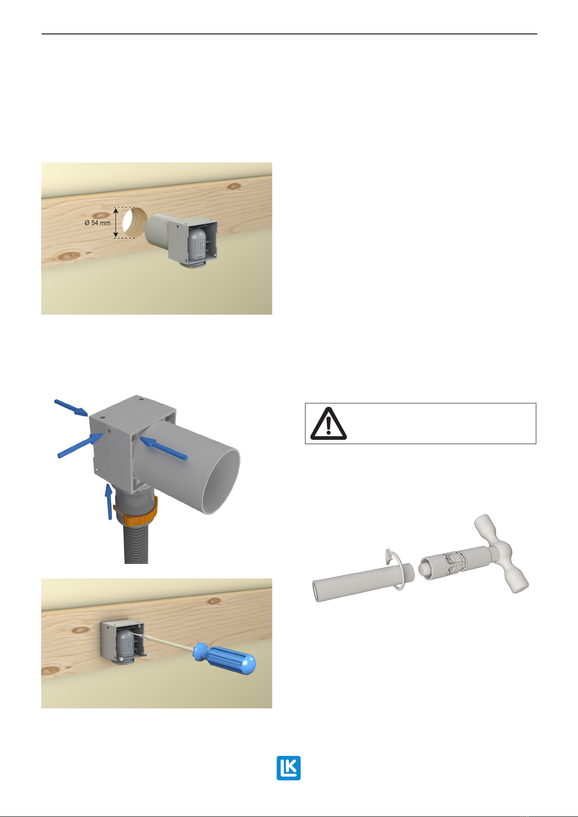
6.1. The wall box is cut down to approximately
2 mm from the completed wall with LK Wall Box
Cutter UNI (Article no. 187 64 94).
If the wall cladding is to have a vinyl covering
then the LK Wall Box Cutter UNI UTV (Article
no. 188 21 54) can be used.
LK Connection couplings
7.1.1 For assembly of tap mixer in accordance with
Swedish standards, LK Connection coupling M26
(Article no. 188 18 45) should be assembled. The
length of the connection should be adjusted and
the thread joint against the angle tting should be
sealed with, for example, ax and thread paste.
Tightening is done with a combination wrench or
a 14 mm Allen key.
NOTE!
Thread tape should not be used on the con-
nection coupling.
7.1.2 For assembly of tap mixer in accordance with
international standards, LK Connection coupling
¾”/ ½” (Article no. 188 18 48) should be assembled.
The length of the connection coupling should be
adjusted so that approximately 10 mm of the ¾”
pipe thread is exposed when the cover plate is tigh
-
tened against the wall. The thread joint against the
angle tting should be sealed with, for example,
ax and thread paste. Thread tape should not be
used. Tightening is done with a 14 mm Allen key.
NOTE!
Thread tape should not be used on the con-
nection coupling.
For more variants of connection couplings, visit:
https://www.lksystems.se/en/products/lk-uni-
versal/products/installation-components/angle-
wall-box-mounting/connection-couplings/
Replacement of PE-X pipe to
LK Wallbox Push
For replacement of LK PE-X Universal Pipe X,
refer to assembly instructions for LK PEX, PAL
and PE-RT.
Accessories for LK Wallbox UNI Push
Reinforcement for Wallbox
LK Reinforcement for Wallbox UNI (Article no.
188 10 66), see picture below, is used when the
mixer needs maximum support. The reinforcement
has a female ½” thread which is screwed onto a
connection coupling. The connection coupling is
then threaded on the wallbox angle tting.
LK Systems AB, Box 66, 161 26 Bromma, Sweden | www.lksystems.se/en
This manual suits for next models
3
Popular Plumbing Product manuals by other brands

noken
noken Smart 100093267-N720000156 manual

BK RESOURCES
BK RESOURCES MSHS-72W1 Assembly instructions

Helvex
Helvex H-13341G installation guide

Maier
Maier DP Series operating instructions

Alpine Saunas
Alpine Saunas HY-YM6008 Installation & owner's manual

Kohler
Kohler STRAYT 45370T-B4 installation instructions

Dundalk LeisureCraft
Dundalk LeisureCraft Outdoor Cedar Cabin Sauna Assembly instructions

Hans Grohe
Hans Grohe Focus M42 120 1jet 71804000 Instructions for use/assembly instructions

Pfister
Pfister LG16 Series manual

Moen
Moen Fina TS51704 Series instruction manual

Helvex
Helvex MAXIMA E-713 installation guide

JCM
JCM 143 installation instructions