LoadSurfer PT15 User manual
PT15 / PT30/PT50 Hydraulic Lift Table
⚫Operation manual
⚫Spare parts catalogue
Unit R1D Rockingham Gate
Poplar Way West
Cabot Park
Bristol
BS11 0YW
Contact Us
Tel: 0808 123 69 69
Fax: 0117 9381 602
Email: [email protected]

1
Ⅰ. Main technical parameters:
PT15
PT30
PT50
Capacity
kg
150
300
500
Max. lift height
mm
725
900
900
Min. height of table
mm
225
280
280
Table size
mm
700X450
815X500
815X500
Handle height
mm
815
970
970
Wheel diameter
mm
100
125
125
Service weight
kg
41
74
82
Ⅱ. Scope of application:
PT series table lift truck is a kind of high-lift transportation tool which is applicable for short-distance
transportation as well as goods lifting and lowering. Besides, it can also be used as station facilities
for workshop.
Ⅲ. Operation condition:
1. Lift table should be operated on solid and flat ground;
2. Operation temperature: -20-40C°.
Ⅳ. Notes(warning):
1. Read the instruction carefully before operation and get to know the performance and operation
requirements of the lift table. And the hydraulic lift table can’t be used unless it is authorized.
2. Do not overload the hydraulic lift table and operate it within the rated load. Overloading will
cause damage to the hydraulic lift table and human body.
3. It is forbidden for operators to stand or sit on the table to work.
4. Don’t put the hands or feet under the lowering table.
5. Please brake the truck when loading goods to prevent it from moving.
6. Off-set loading is forbidden when loading goods, and the goods should be distributed uniformly
on the whole table.
7. Loose or unstable goods are not permitted to be loaded.
8. Don’t put goods on working table for a long time.
9. The truck can’t be moved when goods are being lifted.
10. The truck can only be moved on flat and hard ground, it is forbidden to be used on sloping
ground or rugged ground;
11. When putting goods on table which has been hoisted, the weight of goods should be within
rated load, and the goods should be loaded lightly. (Safety valve only works in hoisting process,
if the truck has been hoisted, and then put overweight goods on it, the safety valve can’t work.
In this way, the truck may be damaged.)
12. When loading and unloading goods on hoisted table, don’t drag goods in cross direction, which

2
may cause serious off-set loading and make truck turn over.
13. When maintaining and repairing truck, stand bar should be used to support fork arm in order to
prevent table from falling (there should be no goods on table), and guarantee the safety in
maintenance and repairing.
14. Please operate strictly according to “notes (warning)”, otherwise it will bring damage to truck
and human body.
Ⅴ. Operation methods:
1. Please step on the foot lever for several times to raise the working table.
2. Please lift the handle knob upward slowly, and open the one-way valve to make the working
table descend slowly.
3. Please make the brake open before moving the truck.
Ⅵ. Maintenance and upkeep:
It is very important to conduct necessary maintenance and upkeep so as to prolong the service life
and safety of the lift table. Please check the lift table before operation according to the following
items:
1. Whether there is any distortion and bending of various positions of the lift table.
2. Please check the brake of the truck and the wearing condition of the wheels.
3. Check oil leakage in the hydraulic system.
4. Please add or fill lubricant to each friction surface before daily operation.
5. If there is any failure, the lift table should be repaired at once, then it can be put into use again.
6. Chang the hydraulic oil every twelve months, choose the following or close brand hydraulic oil
according to the climate conditions of different areas:
a) YBN32 is adaptive under the environment temperature of -10~+40°C;
b) YCN32 is adaptive under the environment temperature of -20~+40°C.
Ⅶ. Assembly method:
The handle and foot lever are dismantled when ex-factory, they might be fixed together by the
users when using. The assembly methods are as follows:
Handle installation method: as shown following drawing, fix the handle (B1) to mounting hole
of the truck body (A) with bolt (B7), spring washer (B6), flat
washer (B5), then screw down the bolt (B7) with wrench.
Foot lever mounting: insert the foot lever (B31) into the hole, put in the screw (B29) and the
plain washer (B27) , the spring washer (B28) ,then screw down the
screw (B29) with wrench.

3
Ⅷ. Name of Parts
HANDLEHANDLEKNOBKNOB
HANDLEHANDLE
FOOTFOOTLEVERLEVER
TABLETABLE
SCISSORSCISSOR
FRAMEFRAME
PUMPPUMP

4
Ⅸ.Spare parts catalogue
1.PumpSpare parts catalogue (PT15)
No.
Name
Qty.
No.
Name
Qty.
B101
Pumpcore
1
B125
Baseforsteelball
1
B102
Coverforspring
1
B126
Retainingringforaxle
1
B103
Spring
1
B127
Leverplate
1
B104
Dustring
1
B128
Pin
1
B105
Sealring
1
B129
O-ring
2
B106
Pumpcylinder
1
B130
Strikepin
1
B107
O-Ring
1
B131
Sealring
1
B108
Pumpbase
1
B132
O-ring
1
B109
Steelball
1
B133
Washerof Nylon
1
B110
Spring
1
B134
Cylinder
1
B111
Screw foradjust pressure
1
B135
Retainingringforaxle
1
B112
O-Ring
1
B136
Piston
1
B113
Baseforsteelball
1
B137
Pistonrod
1
B114
Screw
1
B138
O-ring
1
B115
Steelball
1
B139
O-ring
1
B116
Spring
1
B140
Screwforsealing
1
B117
Steelball
1
B141
Dustring
1
B118
Steelball
1
B142
Housing
1
B119
Steelball
1
B143
Washerof Nylon
1
B120
Spring
1
B144
Cylindercap
1
B121
Valve
1
B145
O-ring
1
B122
Compoundgasket
1
B123
Screwforsealing
1
B124
O-ring
1

5
2. Type PT15 Spare parts catalogue
No.
Name
Qty.
No.
Name
Qty.
B1
Handle
1
B26
Spacerbush
1
B2
Handleknob
1
B27
Washer
1
B3
BrakeLine
1
B28
Springwasher
1
B4
Springpin
1
B29
Screw
1
B5
Washer
2
B30
Robbertube
1
B6
SpringWasher
2
B31
Footlever
1
B7
Screw
2
B32
Connectingrod
1
B8
Screw
2
B33
Table
1
B9
Nut
2
B34
Scissor
1
B10
Retainingringforaxle
1
B35
Retainingringforaxle
4
B11
Bush
2
B36
Shaft
4
B12
Axle
1
B37
Pulley
4
B13
Pump
1
B38
Frame
1
B14
Clampscrew
1
B39
Screw
8
B15
Washer
1
B40
Washer
16
B16
Nut
1
B41
Universalwheel
2
B17
Retainingringforaxle
2
B42
Nut
8
B18
Shaft
1
B43
Nut
4
B19
Longspacerbush
1
B44
Baseforuniversalwheel
2
B20
Shortspacerbush
1
B45
Dustcover
4
B21
Cotter
2
B46
Wheel
4
B22
Pin
1
B47
Breakpad
2
B23
Link
2
B48
Breaklever
2
B24
Washer
2
B49
Screw
4
B25
Pin
1

6
3.PumpSpare parts catalogue (Type PT30/PT50)
No.
Name
Qty.
No.
Name
Qty.
X910
Coverfor spring
1
X935
O-ring
1
X911
Spring
1
X936
Washer
1
X912
Pump core
1
X937
Spring
1
X913
Dust ring
1
X938
O-ring
1
X914
Seal ring
1
X939
O-ring
1
X915
Pump cylinder
1
X940
Spring
1
X916
Washer
1
X941
Valve
1
X917
Big Nylon washer
2
X942
Valve
1
X918
Small Nylonwasher
1
X943
Strikepin
1
X919
Cylinder
1
X944
Strikepinbase
1
X920
Retainingring foraxle
1
X945
Ball
1
X921
Seal ring
1
X946
Springbase
1
X922
Piston
1
X947
Spring
1
X923
O-Ring
1
X948
O-ring
1
X924
Piston rod
1
X949
Screw
1
X925
Housing
1
X950
Nut
1
X926
Base
1
X951
Bolt
1
X927
Cylindercap
1
X952
Retainingring foraxle
1
X928
O-ring
1
X953
Pin
1
X929
Dust ring
1
X954
Ball
1
X930
Screw
1
X955
Ball
1
X931
O-ring
1
X956
Spring
1
X932
Valvecover
1
X957
Ball
1
X933
Valve
1
X958
Bolt
1
X934
Lever plate
1
7
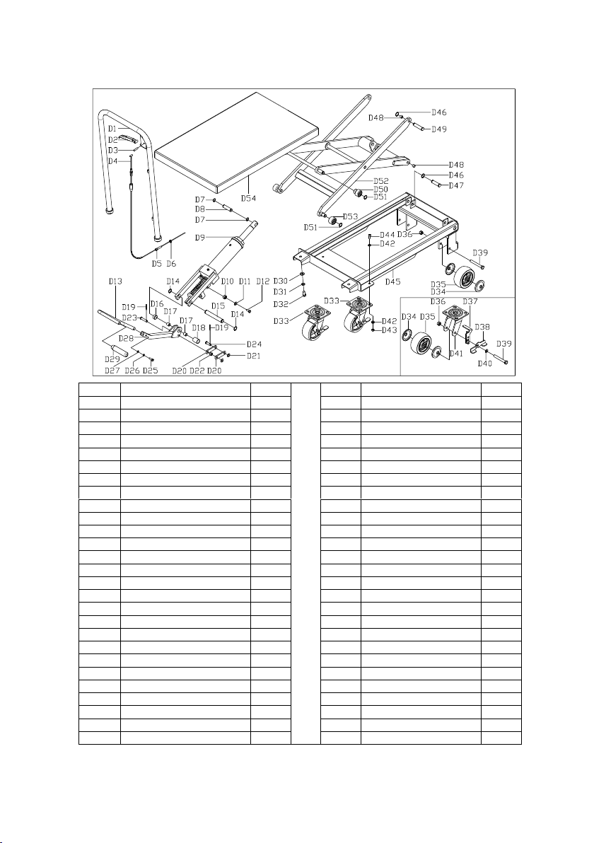
4.Type PT30/PT50 Spare parts catalogue
No.
Name
Qty.
No.
Name
Qty.
D1
Handle
1
D28
Connectingrod
1
D2
Handleknob
1
D29
Robbertube
1
D3
Springpin
1
D30
Washer
2
D4
BrakeLine
1
D31
Springwasher
2
D5
Screw
2
D32
Screw
2
D6
Nut
2
D33
Universalwheel
2
D7
Retainingringforaxle
2
D34
Dustcover
8
D8
Axle
1
D35
Wheel
4
D9
Pump
1
D36
Nut
4
D10
Nut
1
D37
Breakpad
2
D11
Washer
1
D38
Breaklever
2
D12
Clampscrew
1
D39
Bolt
4
D13
Foot lever
1
D40
Washer
2
D14
Retainingringforaxle
2
D41
Baseforuniversalwheel
2
D15
Shaft
1
D42
Washer
16
D16
Shortspacerbush
1
D43
Nut
8
D17
Bush
2
D44
Screw
8
D18
Long spacerbush
1
D45
Frame
1
D19
Cotter
2
D46
Retainingringforaxle
4
D20
Link
2
D47
Shaft
2
D21
Washer
2
D48
Bush
4
D22
Spacerbush
1
D49
Shaft
2
D23
pin
1
D50
Pulley
2
D24
Pin
1
D51
Retainingringforaxle
4
D25
Screw
1
D52
Scissor
1
D26
Springwasher
1
D53
Pulley
2
D27
Washer
1
D54
Table
1

8
Unit R1D Rockingham Gate
Poplar Way West
Cabot Park
Bristol
BS11 0YW
Contact Us
Tel: 0808 123 69 69
Fax: 0117 9381 602
Email: [email protected]
This manual suits for next models
2
Popular Indoor Furnishing manuals by other brands

Regency
Regency LWMS3015 Assembly instructions

Furniture of America
Furniture of America CM7751C Assembly instructions

Safavieh Furniture
Safavieh Furniture Estella CNS5731 manual

PLACES OF STYLE
PLACES OF STYLE Ovalfuss Assembly instruction

Trasman
Trasman 1138 Bo1 Assembly manual

Costway
Costway JV10856 manual


