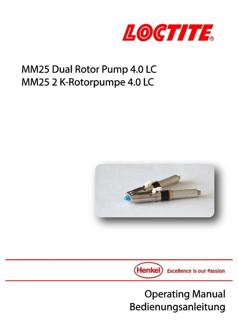
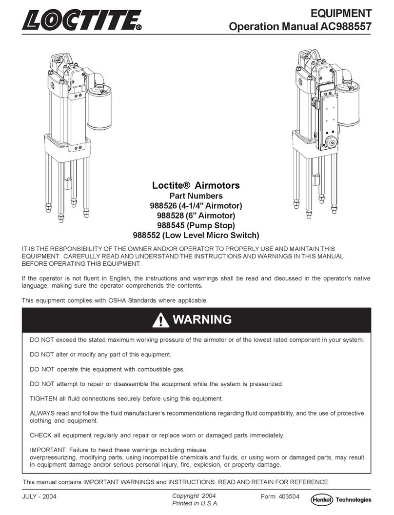
Loctite 988530 User manual

EQUIPMENT
Operation Manual AB988556
IT IS THE RESPONSIBILITY OF THE OWNER AND/OR OPERATOR TO PROPERLY USE AND MAINTAIN THIS
EQUIPMENT. CAREFULLY READ AND UNDERSTAND THE INSTRUCTIONS AND WARNINGS IN THIS MANUAL
BEFORE OPERATING THIS EQUIPMENT.
If the operator is not fluent in English, the instructions and warnings shall be read and discussed in the operator’s native
language, making sure the operator comprehends the contents.
This equipment complies with OSHA Standards where applicable.
SEPT - 2004
This manual contains IMPORTANT WARNINGS and INSTRUCTIONS. READ AND RETAIN FOR REFERENCE.
Loctite® High Viscosity Paste Pumptubes
Part Numbers
988530 (Carbon Steel 22:1, 44:1)
988532 ( Inert 22:1, 44:1)
988533 (Carbon Steel 64:1)
988535 (Inert 64:1)
988837 (Carbon Steel with Inert Seals 22:1, 44:1)
988840 (Carbon Steel with Inert seals 64:1)
Copyright 2004
Printed in U.S.A.
Form 403503
DO NOT exceed the stated maximum working pressure of the airmotor or of the lowest rated component in your system.
DO NOT alter or modify any part of this equipment.
DO NOT operate this equipment with combustible gas.
DO NOT attempt to repair or disassemble the equipment while the system is pressurized.
TIGHTEN all fluid connections securely before using this equipment.
ALWAYS read and follow the fluid manufacturer’s recommendations regarding fluid compatibility, and the use of protective
clothing and equipment.
CHECK all equipment regularly and repair or replace worn or damaged parts immediately.
IMPORTANT: Failure to heed these warnings including misuse, overpressurizing, modifying parts, using incompatible
chemicals and fluids, or using worn or damaged parts, may result in equipment damage and/or serious personal injury,
fire, explosion, or property damage.

Page Number - 2
in. (mm)
988526 22:1 4400 psi (304 bar) 200 psi (14 bar) 62-1/4 (1581)
988528 44:1 4400 psi (304 bar) 100 psi (7 bar) 61-3/8 (1559)
988533, 988535, 988840 988528 64:1 6400 psi (442 bar) 100 psi (7 bar) 61-3/8 (1559)
988530, 988532, 988837
PUMP CHART
Pumptube Airmotor* Ratio Maximum Delivery Maximum Air Dimension "A"
Pressure Pressure
SPECIFICATIONS
Pump Stroke – 6 in. (152 mm)
Max. recommended speed (continuous) – 75 cycles/min.
Output per cycle:
988530, 988532, 988837 – 6.7 cu. in. (110 cc)
988533, 988535, 988840 – 4.6 cu. in. (75 cc)
Approx. cycles per gallon (liter):
988530, 988532, 988837 – 35 (9)
988533, 988535, 988840 – 51 (13)
Output at 75 cycles/min.:
988530, 988532, 988837 – 2.2 gpm (8.2 liter/min.)
988533, 988535, 988840 – 1.5 gpm (5.7 liter/min.)
Wetted part materials:
988530, 988533 – Carbon Steel, Bronze, Polyurethane, Nitrile
988532, 988535 – Inert Metal, Stainless Steel, Delrin,
UHMW Polyethylene, Teflon
988837, 988840 – Carbon Steel, UHMW Polyethylene, Teflon
*Refer to Airmotor Operation Manual, AC988557
Airmotor*
3/4” NPTF
Lube Outlet
Pumptube

Page Number - 3
ATTACHING AIRMOTOR
TO PUMPTUBE
1. Tightly attach tie rods to the airmotor (use
short threaded end of the tie rods).
2. Mount airmotor on top of the pump-tube
outlet and tightly connect Coupling Nut (Item
2) to airmotor piston rod.
3. Hand tighten tie rods to the pumptube
with four nuts supplied with airmotor.
4. Slowly cycle the pump several times,
using just enough air pressure to operate
the pump without stalling.
5. Stop the pump on an “up” stroke and
tighten the four nuts to securely fasten the
airmotor to the pumptube.
OPERATING PRECAUTIONS
Use Loctite replacement parts to assure
compatible pressure rating. HEED ALL
WARNINGS.
Be sure material hoses and other compo-
nents are able to withstand fluid pressures
developed by this pump.
Do not operate pump continuously at
speeds in excess of 75 cycles per minute.
Disconnect air line from pump air-motor
when system sits idle for long periods of
time.
SERVICING. Before servicing or cleaning
pump, or removing fluid hose or gun from a
unit that has been used, be sure to discon-
nect air lines and carefully bleed pressure
off of the system.
Check continuity (a good static wire connec-
tion) with an ohmmeter. Place one probe on
one hose fitting and the other probe on other
hose fitting, continuity or proper grounding
through hose is good when a reading is
obtained on the ohmmeter. PREVENT
FIRES. When pumping, flushing or recircu-
lating volatile solvents, the area must be
adequately ventilated.
• Keep solvents away from heat, sparks and
open flames. Keep containers closed when
not in use.
PUMP PRIMING
To begin operation, the pump has to
be primed with the pumped material.
The pump is a double acting (pumps
material on “up” & “down” stroke)
positive displacement reciprocating
pump and as such intakes material
only on the “up” stroke.
To prime pump, open output line
(material valve) and slowly open air
supply valve until pump starts. Allow
pump to cycle very slowly until all air is
pushed out of lines and material fills
up pump and lines. Close output line
(material shut-off valve) - pump should
stall against pressure.
Note: Pumps are factory tested with
light oil and some of it is left in to
protect pump parts during storage and
transportation. To prevent contamina-
tion of material to be pumped, flush
pump before using.
PREVENT STATIC SPARKING. If static
sparking occurs, fire or explosion could
result. Pump, dispensing valve, and
containers must be grounded when
handling flammable fluids such as
petroleum products, paints, lacquers,
etc. and wherever discharge of static
electricity is hazard.
DO NOT allow pump to operate when
out of material.

Page Number - 4
DISASSEMBLY Tools
Required
2-1/8" Dia. Strap Wrench
Retaining Ring Pliers (External)
Retaining Ring Pliers (Internal)
11/16" Hex Wrench
7/8" Hex Wrench
13/16" Hex Wrench
1-3/8" Hex Wrench
2-1/4" Hex Wrench
Pliers
Procedure
1. Remove Priming Tube (Item 42)
from Adapter Tube (Item 30).
2. Remove Cotter Pin (Item 40) from
from Priming Plunger (Item 39).
3. Remove Priming Shovel (Item 41)
from Priming Plunger (Item 39).
4. Unscrew Adapter Tube (Item 30)
from Pump Tube (Item 21) and
slide off of Piston Assembly (Items
25, 27 & 28).
5. Remove Priming Plunger (Item 39)
from Piston Body (Item 28).
6. Remove Check Seat (Item 38) and
O-ring (Item 37) from Adapter Tube
(Item 30).
7. Remove Check Assembly (Items
31, 32, 33, 34, 35, & 36) from
Adapter Tube (Item 30).
8. Remove Retaining Ring (Item 31)
and Guide Washer (Item 32) from
Check (Item 36).
9. Remove Retaining Ring (Item 33),
Packing Washer (Item 34) and U-
cup Packing (Item 35) from Check
(Item 36).
10. Remove Lube Cup (Item 4) from
Gland Nut (Item 6).
11. Remove Bolt Connector (Item 1)
from plunger (Item 3).
12. Pull Piston Assembly (Items 25,
27 & 28) to remove Plunger (Item
3), Connecting Rod (Item 23),
Adapter (Item 24) and Piston
Assembly from Pump Tube (Item
21).
13. Remove Pump Tube (Item 21)
from Outlet Body (Item 12).
14. Remove O-ring (Item 20) from
Outlet Body (Item 12).
15. Remove Gland Nut (Item 6) from
Outlet Body (Item 12).
16. Remove Sleeve (Item 11) from
Outlet Body (Item 12).
17. Remove Priming Plug (Item 13)
and Adapter (Item 14) from Outlet
Body (Item 12).
18. Remove Outlet Body (Item 19)
from Outlet Body (Item 12).
19. Remove Ball (Item 17), Check Seat
(Item 16) and Gaskets (Item 15)
from Outlet Body (Item 12).
20. Remove Retaining Ring (Item 10),
Packing Washer (Item 9) and U-
cup Packing (Item 8) from Gland
Nut (Item 6).
21. Remove Piston Adapter (Item 25)
from Adapter (Item 24).
22. Remove Ball (Item 17) from
Adapter (Item 24).
23. Remove Cotter Pins (Item 22) from
Connecting Rod (Item 23).
24. Remove Adapter (Item 24) and
Plunger (Item 3) from Connecting
Rod (Item 23).
25. Unscrew Piston Adapter (Item 25)
and remove Piston Collar (Item 27)
from Piston Body (Item 28).
26. Remove U-cup Packings (Item 26)
from Piston Adapter (Item 25) and
Piston Body (Item 28).
Problem Possible Cause Solution
Pump does not operate. Restricted or inadequate air supply. Check air supply pressure and air hose
diameter (see Airmotor manual for
minimum air supply hose diameter).
Obstructed material output. Check output line for restrictions.
Erratic or accelerated operation. Pump is not primed. Prime pump (see "Pump Priming"
instructions).
Ins ufficient m aterial supply. Refill material supply.
Material is too heavy for priming. Lower output with material valve. Increase
pressure to pressure primer (if in use).
Check for inlet restrictions.
Pump operates on "down" stroke only Worn or damaged Piston U-cups (Item26) Check and replace if needed.
(missing "up" stroke). or Piston Check (Items 17 & 25).
Pump operates on "up" stroke only Worn or damaged Inlet Check (Items 36 Check and replace if needed.
(missing "down" stroke). & 38).
Insufficient material supply. Pump is not Check inlet for restrictions. Lower output
intaking enough material to dispense on with material valve.
both strokes.
Pump is operating but not dispensing Inlet Check (Items 36 & 38) is not seating Check and replace if needed.
material. or is damaged.
TROUBLESHOOTING
PUMP REPAIR KITS
988713 - Includes soft parts for Part No. 988530
988714 - Includes soft parts for Part No. 988533
988838 - Includes soft parts for Part No. 988532 & 988837
988841 - Includes soft parts for Part No. 988535 & 988840

Page Number - 5
Item Part No. Part No. Part No. Part No. Part No. Part No.
No. Description Qty. 988530 988532 988533 988535 988837 988840
1 Bolt Connector 1 AB236225 AB236225 AB236225 AB236225 AB236225 AB236225
2 Coupling Nut 1 AB237051 AB237051 AB237051 AB237051 AB237051 AB237051
3 Plunger 1 AB242914 AB273809 AB242916 AB273808 AB242914 AB242916
4 Lube Cup 1 AB242231 AB242231 AB242231 AB242231 AB242231 AB242231
5 O-ring 1 (Note #1) (Note #2) (Note #3) (Note #4) (Note #2) (Note #4)
6 Gland Nut 1 AB242915 AB273810 AB242917 AB273811 AB242915 AB242917
7 O-ring 1 (Note #1) (Note #2) (Note #3) (Note #4) (Note #2) (Note #4)
8 U-cup 1 (Note #1) (Note #2) (Note #3) (Note #4) (Note #2) (Note #4)
9 Packing Washer 1 (Note #1) (Note #2) (Note #3) (Note #4) (Note #2) (Note #4)
10 Retaining Ring 1 (Note #1) (Note #2) (Note #3) (Note #4) (Note #2) (Note #4)
11 Sleeve 1 AB86241 AB273813 AB86240 AB273812 AB86241 AB86240
12 Outlet Body 1 AB242216 AB273641 AB242216 AB273641 AB242216 AB242216
13 Priming Plug 1 AB16382 AB273631 AB16382 AB273631 AB16382 AB16382
14 Adapter 1 AB16381 AB273630 AB16381 AB273630 AB16381 AB16381
15 Gasket 2 (Note #1) (Note #2) (Note #3) (Note #4) (Note #2) (Note #4)
16 Outlet Check 1 AB11948 AB273627 AB11948 AB273627 AB11948 AB11948
17 Ball 2 AB66285 AB273636 AB66285 AB273636 AB66285 AB66285
18 Ball Stop 1 AB57036 AB273635 AB57036 AB273635 AB57036 AB57036
19 Outlet Body 1 AB12017 AB273628 AB12017 AB273628 AB12017 AB12017
20 O-ring 1 (Note #1) (Note #2) (Note #3) (Note #4) (Note #2) (Note #4)
21 Pump Tube 1 AB242396 AB273654 AB242396 AB273654 AB242396 AB242396
22 Cotter Pin 2 (Note #1) (Note #2) (Note #3) (Note #4) (Note #2) (Note #4)
23 Connecting Rod 1 AB242397 AB273655 AB242397 AB273655 AB242397 AB242397
24 Adapter 1 AB242380 AB273643 AB242380 AB273643 AB242380 AB242380
25 Piston Adapter 1 AB242691 AB273665 AB242689 AB273663 AB242691 AB242689
26 U-cup 2 (Note #1) (Note #2) (Note #3) (Note #4) (Note #2) (Note #4)
27 Piston Collar 1 AB242410 AB273660 AB242400 AB273657 AB242410 AB242400
28 Piston Body 1 AB242692 AB273666 AB242690 AB273664 AB242692 AB242690
29 O-ring 1 (Note #1) (Note #2) (Note #3) (Note #4) (Note #2) (Note #4)
30 Adapter Tube 1 AB242409 AB273659 AB242398 AB273656 AB242409 AB242398
31 Retaining Ring 1 (Note #1) (Note #2) (Note #3) (Note #4) (Note #2) (Note #4)
32 Guide Washer 1 (Note #1) (Note #2) (Note #3) (Note #4) (Note #2) (Note #4)
33 Retaining Ring 1 (Note #1) (Note #2) (Note #3) (Note #4) (Note #2) (Note #4)
34 Packing Washer 1 (Note #1) (Note #2) (Note #3) (Note #4) (Note #2) (Note #4)
35 U-cup 1 (Note #1) (Note #2) (Note #3) (Note #4) (Note #2) (Note #4)
36 Check 1 AB242918 AB273814 AB242918 AB273814 AB242918 AB242918
37 O-ring 1 (Note #1) (Note #2) (Note #3) (Note #4) (Note #2) (Note #4)
38 Check Seat 1 AB242919 AB273815 AB242919 AB273815 AB242919 AB242919
39 Priming Plunger 1 AB242920 AB273816 AB242920 AB273816 AB242920 AB242920
40 Cotter Pin 1 (Note #1) (Note #2) (Note #3) (Note #4) (Note #2) (Note #4)
41 Priming Shovel 1 AB13235 AB273629 AB13235 AB273629 AB13235 AB13235
42 Priming Tube 1 AB242375 AB273642 AB242375 AB273642 AB242375 AB242375
Notes:
1. Included in Repair Kit 988713
2. Included in Repair Kit 988838
3. Included in Repair Kit 988714
4. Included in Repair Kit 988841
PARTS LIST

Page Number - 6
WARRANTY
Henkel expressly warrants that all products referred to in this Instruction Manual for Items 988530, 988532, 988533, 988535,
988837 & 988840 Pumptubes (hereafter called “Products”) shall be free from defects in materials and workmanship. Liability
for Henkel shall be limited, as its option, to replacing those Products which are shown to be defective in either materials or
workmanship or to credit the purchaser the amount of the purchase price thereof (plus freight and insurance charges paid
therefor by the user). The purchaser’s sole and exclusive remedy for breach of warranty shall be such replacement or credit.
A claim of defect in materials or workmanship in any Products shall be allowed only when it is submitted in writing within one
month after discovery of the defect or after the time the defect should reasonably have been discovered and in any event, within
(12) months after the delivery of the Products to the purchaser. This warranty does not apply to perishable items, such as seals,
wipers, fuses, filters, etc. No such claim shall be allowed in respect of products which have been neglected or improperly
stored, transported, handled, installed, connected, operated, used or maintained. In the event of unauthorized modification of
the Products including, where products, parts or attachments for use in connection with the Products are available from
Henkel, the use of products, parts or attachments which are not manufactured by Henkel, no claim shall be allowed.
No Products shall be returned to Henkel for any reason without prior written approval from Henkel. Products shall be returned
freight prepaid, in accordance with instructions from Henkel.
NO WARRANTY IS EXTENDED TO ANY EQUIPMENT WHICH HAS BEEN ALTERED, MISUSED, NEGLECTED, OR DAMAGED
BY ACCIDENT, OR IF THE SYSTEM WAS USED TO DISPENSE ANY LIQUID MATERIAL OTHER THAN HENKEL PRODUCTS.
EXCEPT FOR THE EXPRESS WARRANTY CONTAINED IN THIS SECTION, HENKEL MAKES NO WARRANTY OF ANY KIND
WHATSOEVER, EXPRESS OR IMPLIED, WITH RESPECT TO THE PRODUCTS.
ALL WARRANTIES OF MERCHANTABILITY, FITNESS FOR A PARTICULAR PURPOSE, AND OTHER WARRANTIES OF WHAT-
EVER KIND (INCLUDING AGAINST PATENT OR TRADEMARK INFRINGEMENT) ARE HEREBY DISCLAIMED BY HENKEL AND
WAIVED BY THE PURCHASER.
THIS SECTION SETS FORTH EXCLUSIVELY ALL OF LIABILITY FOR HENKEL TO THE PURCHASER IN CONTRACT, IN TORT
OR OTHERWISE IN THE EVENT OF DEFECTIVE PRODUCTS.
WITHOUT LIMITATION OF THE FOREGOING, TO THE FULLEST EXTENT POSSIBLE UNDER APPLICABLE LAWS, HENKEL
EXPRESSLY DISCLAIMS ANY LIABILITY WHATSOEVER FOR ANY DAMAGES INCURRED DIRECTLY OR INDIRECTLY IN
CONNECTION WITH THE SALE OR USE OF, OR OTHERWISE IN CONNECTION WITH, THE PRODUCTS, INCLUDING,
WITHOUT LIMITATION, LOSS OF PROFITS AND SPECIAL, INDIRECT OR CONSEQUENTIAL DAMAGES, WHETHER CAUSED
BY NEGLIGENCE FROM HENKEL OR OTHERWISE.
Henkel Corporation Henkel Canada Corporation Henkel Capital S.A. de C.V.
1001 Trout Brook Crossing 2225 Meadowpine Boulevard Calzada de la Viga s/n Fracc. Los Laureles
Rocky Hill, CT 06067-3910 Mississauga, Ontario L5N 7P2 Loc. Tulpetlac, C.P. 55090
Ecatepac de Morelos Edo. de México
Henkel Automotive Henkel Ltda.
Technology Center Rua Karl Huller, 136 - Jd. www.loctite com
2455 Featherstone Road Canhema 09941-410
Auburn Hills, Michigan 48326 Diadema/SP, Brazil
Loctite is a registered trademark of Henkel Corporation, U.S.A . © Copyright 2004. Henkel Corporation. All rights reserved. Data
in this operation manual is subject to change without notice.
This manual suits for next models
5
Table of contents
Other Loctite Water Pump manuals
Popular Water Pump manuals by other brands

SAB
SAB F101 Instructions for use

Jacuzzi
Jacuzzi JVS185S owner's manual

yellow jacket
yellow jacket SuperEvac 9358 series Operation and maintenance manual

Ingersoll-Rand
Ingersoll-Rand ARO WLM2203A 2 Series Operator's manual

VT
VT Econo 2000 User instructions

teel
teel 4RJ47 Operating instructions & parts manual