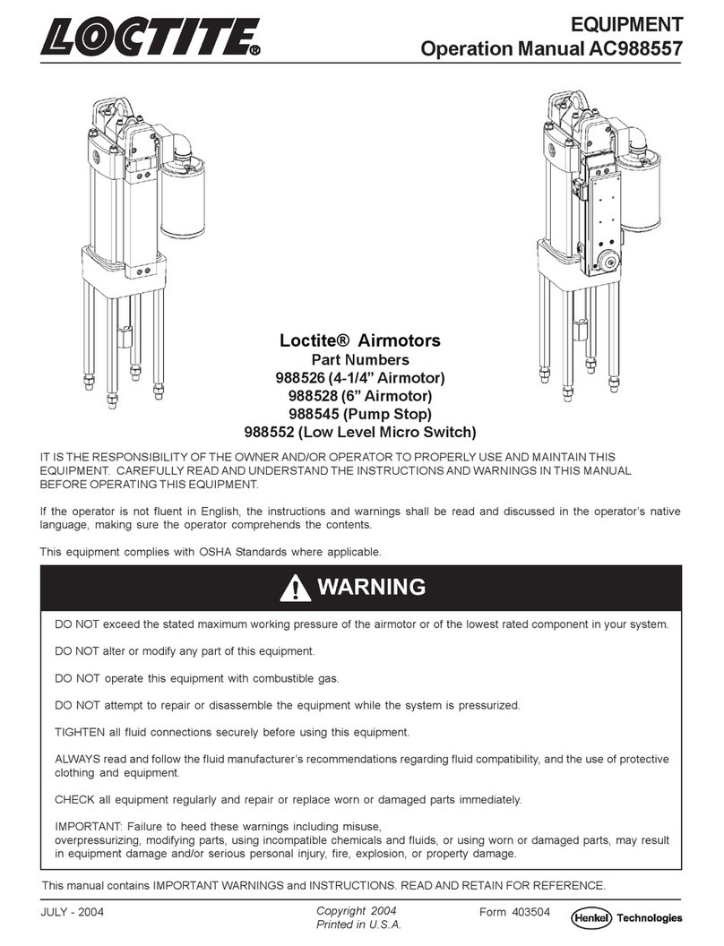
Loctite 988514 User manual

EQUIPMENT
Operation Manual AA988555
IT IS THE RESPONSIBILITY OF THE OWNER AND/OR OPERATOR TO PROPERLY USE AND MAINTAIN THIS
EQUIPMENT. CAREFULLY READ AND UNDERSTAND THE INSTRUCTIONS AND WARNINGS IN THIS MANUAL
BEFORE OPERATING THIS EQUIPMENT.
If the operator is not fluent in English, the instructions and warnings shall be read and discussed in the operator’s native
language, making sure the operator comprehends the contents.
This equipment complies with OSHA Standards where applicable.
SEP - 2004
This manual contains IMPORTANT WARNINGS and INSTRUCTIONS. READ AND RETAIN FOR REFERENCE.
Loctite® Low Viscosity Fluid
Pumps 3:1 and 14:1 Ratios
Part Numbers
988514 (3:1 Carbon Steel, 55 Gal.)
988516 (3:1 Inert, 55 Gal.)
988517 (3:1 Carbon Steel, 5 Gal.)
988519 (3:1 Inert, 5 Gal.)
988520 (14:1 Carbon Steel, 55 Gal.)
988522 (14:1 Inert, 55 Gal.)
988523 (14:1 Carbon Steel, 5 Gal.)
988525 (14:1 Inert, 5 gal.)
988543 (Pump Hoist)
988554 (Wall Mount Kit)
Copyright 2004
Printed in U.S.A.
Form 403502
DO NOT exceed the stated maximum working pressure of the airmotor or of the lowest rated component in your system.
DO NOT alter or modify any part of this equipment.
DO NOT operate this equipment with combustible gas.
DO NOT attempt to repair or disassemble the equipment while the system is pressurized.
TIGHTEN all fluid connections securely before using this equipment.
ALWAYS read and follow the fluid manufacturer’s recommendations regarding fluid compatibility, and the use of protective
clothing and equipment.
CHECK all equipment regularly and repair or replace worn or damaged parts immediately.
IMPORTANT: Failure to heed these warnings including misuse, overpressurizing, modifying parts, using incompatible
chemicals and fluids, or using worn or damaged parts, may result in equipment damage and/or serious personal injury,
fire, explosion, or property damage.

Page Number - 2
Part Nos. 988514, 988516, 988517, 988519
3:1 Low Viscosity Fluid Pumps
SPECIFICATIONS
Airmotor effective dia. in. 2.0
Stroke, in. 4.8
Air inlet 1/4" NPT
Material outlet 1/2" NPT
Liquid to Air Pressure Ratio 3:1
Delivery output, G.P.M. 6
Delivery in cubic inches per cycle 7.9
Suction head, ft. of oil primed pump 25
Minimum air pressure 40 p.s.i.
Maximum air pressure 200 p.s.i.
Max output pressure 600 p.s.i.
Noise level @ 120 psig < 85 dBA
DESCRIPTION
The 3:1 Low Viscosity Fluid Pump is
designed to pump low and medium
viscosity materials. The pump is self-
priming and develops a suction head
up to 25 ft. of oil after priming.
OWNER/OPERATOR
RESPONSIBILITY
It is the owners/operators responsibili-
ty to properly use and maintain this
equipment.
The instructions and warnings con-
tained in this manual shall be read
and understood by the owner/operator
prior to operating this equipment.
If an owner/operator does not under-
stand English,the contents of this
manual shall be explained in the
owners/ operators native language to
assure the owner/operator compre-
hends.
It is the owners/operators responsibili-
ty to maintain the legibility of all warn-
ing and instruction labels.
The owner/operator shall retain this
manual for future reference to Impor-
tant warnings, operating and mainte-
nance Instructions.
SAFETY INFORMATION
Read and understand all warnings,
cautions and instructions before
operating this equipment. Extreme
caution should be used when operat-
ing this equipment as personal injury
and/ or property damage can result
from equipment misuse. Adequate
personal protection is recommended
to prevent splashing of material on the
skin or in the eyes. ALWAYS disconnect
air coupler from pump when the pump
is not being used.

Page Number - 3
3:1 Low Viscosity Fluid Pumps
PRESSURE RELIEF
PROCEDURE
Always perform this procedure when the pump is shut off
and before checking, servicing, installing, cleaning or
repairing any part of this system.
Perform the following procedure:
A. Disconnect the air supply to the pump.
B. Point the dispensing valve away from yourself and
others.
C. Open the dispensing valve into an appropriate container
until the pressure is relieved.
If the above procedure does not relieve the pressure, the
dispensing valve or hose may be restricted. To relieve the
pressure, very slowly loosen the hose end coupling. Then
loosen completely and clear the dispensing valve and/or
hose.
OPERATION
BEFORE USING PUMP
Prior to operation or maintenance a visual inspection shall
be made. Check pump system for leaks, worn or missing
parts.
Any pump that appears to be damaged in any way, is badly
worn or operates abnormally shall be removed from use
until repairs are made. Contact a factory authorized service
center for repairs.
If overpressurizing of the equipment is believed to have
occurred, contact a factory authorized service center for
inspection of the pump.
Annual inspection by a factory authorized service center is
recommended.
USING PUMP
LUBRICATION
An air line filter/regulator/lubricator Is recommended for use
with your Loctite pump to remove harmful dirt and moisture
from your compressor air supply, and to provide automatic air
motor lubrication.
MATERIAL RESTRICTION PREVENTION
Flush the system as required with a compatible solvent to
prevent material buildup when pumping material that dries or
hardens.
The pump was tested in lightweight oil which was left in
to protect the pump from corrosion. Flushing the pump
before connecting it to the system might be desired to
prevent possible contamination of the fluid you are
pumping.
To reduce the risk of injury from splashing or static
sparking when flushing the pump with solvents, always
hold a metal part of the dispensing valve firmly to the side
of a grounded metal pail and operate pump at lowest
possible fluid pressure.
To start pump, turn on the main air supply. Slowly open the
air regulator. Regulate air pressure from 20-40 psig and
throttle to prime pump. Open the dispensing valve to allow
air to be purged from the system. Allow pump to cycle until
fluid without air pockets flows from dispensing valve, then
close dispensing valve.
After pump is primed, adjust air pressure to achieve a
smooth flow of fluid from the dispensing valve. Do not allow
pump to operate when out of material. Pump will accelerate
quickly and run too fast, resulting in costly damage to the
pump.
If the pump accelerates quickly or is running too fast, stop it
immediately. Check the fluid supply and refill it If necessary.
Prime the pump to remove all air from the system, or flush
the pump and relieve pressure.
In a direct supply system, with adequate air pressure sup-
plied to the motor, the pump starts when the gun or dispens-
ing valve is opened and stalls against pressure when it is
closed.
Use the air regulator to control pump speed and fluid pres-
sure. Always use the lowest pressure required to achieve the
desired results. Higher pressures will cause pump packings
to wear prematurely.
MAINTENANCE
To prevent personal injury, perform PRESSURE RELIEF
PROCEDURE before and after operating the pump and
before performing any maintenance.
To prevent personal injury, perform PRESSURE RELIEF
PROCEDURE before and after operating the pump.

Page Number - 4
DISASSEMBLY
A. Remove valve cap (Item #1), trip rod pin (Item #2) and
trip collar (Item #21).
B. Remove four tie nuts (Item #45) from tie rods
(Item #44).
C. Unscrew trip sleeve (Item #55) from the trip rod
(Item #28) and lift air valve casting (Item # 4) off of air
cylinder (Item # 29).
D. Remove packing nut (Item #42) and packing cap
(Item #39) from air valve casting. Remove the packing
(Item #40) and packing washer (Item #41).
E. Remove four screws (Item #59) and cover (Item #58)
with the O-ring (Item #57).
F. Remove four screws (Item #38), toggle plate (Item #56),
trip shoe (Item #53) and trip sleeve (Item #55).
G. Remove four valve seat screws (Item #52), four springs
(Item #51), valve guide plate (Item #54) with two springs
(Item #46), two balls (Item #48) and valve slide and seat
kit (Item #49) with gasket (Item #47).
H. Unscrew trip rod packing nut (Item #25) from air valve
casting and remove all packing and gaskets.
I. Unscrew foot valve body (Item #35) and pump tube
(Item #33) from outlet casting (Item #14).
J. Remove air cylinder (Item #29) and air passage tube
(Item #8) from outlet casting.
K. Place wrench on piston seat (Item #18) and connecting
rod (Item #32). Remove piston seat (Item #18) and
piston (Item #17) with two packings (Item #16) and
spring stop (Item #15).
L. Place wrench on piston bolt (Item #5) and piston rod
(Item #27) and remove piston bolt (Item #5), piston
packing (Item #26), two washers (Item #7) and trip rod
(Item #28).
M. Unscrew gland packing nut (Item #9) from outlet casting
and remove all gland seal parts.
3:1 Low Viscosity Fluid Pumps
NOTE
If complete disassembly is required, order the repair kit
and replace ALL gaskets, O-rings and packings.
To prevent personal injury perform PRESSURE RELIEF
PROCEDURE before and after operating and before
performing any disassembly or assembly.
TROUBLESHOOTING
If the following procedures do not correct the problem,
contact a factory authorized service center.
PROBLEMS
AIRMOTOR DOES NOT OPERATE.
• Check air supply to pump.
• Check trip rod pin (Item #2), trip rod (Item #28) and
toggle assembly (Item #56) for breakage or loose parts.
AIR SEEPAGE FROM AIR EXHAUST WHILE PUMP IS NOT
OPERATING
• Check valve slide and seat kit (Item #49) and gasket
(Item #47), trip rod packing (Item #24) and washer
(Item #23). Replace if necessary.
LOSS OF PRESSURE, VOLUME OR CONTINUOUS
OPERATION OF PUMP WHEN NOT IN NORMAL USE.
• Clean piston seat and ball foot valve.
• If worn or damaged, replace piston (Item #17), piston
seat (Item #18) and piston packings (Item #16).
• Check inside diameter of pump tube (Item #33).
If scored, replace pump tube.
ASSEMBLY
To reassemble, perform DISASSEMBLY procedures in
reverse.

Page Number - 5
3:1 Low Viscosity Fluid Pumps
1
221
3
4
5
22
23
24
25
Tighten to 10-15
Ft. Lbs. of Torque.
6
7
26
Use Loctite 510 Gasket
Eliminator on Threads.
27
28
8
29
9
10
30
11
12
10
9
27
13
31
31
13
14
15
32 Use Loctite 510 Gasket
Eliminator on Threads
16
17
33
18
19
20
34
35
1-1/2” NPTF (Male)
1” NPTF (Female)

Page Number - 6
3:1 Low Viscosity Fluid Pumps
36
37
50
46 47 48
49
38
Tighten to 30-40
Inch Lbs. of Torque
39
40
41
42
43
44
45
47
49
51
52
Tighten to 30-40 Inch
Lbs. of Torque
38
Tighten to 30-
40 Inch Lbs. of
Torque
54
55
56
57
58
59
Tighten to 90-100
Inch Lbs. of Torque
IMPORTANT
START FASTENERS BY HAND TO
AVOID STRIPPING THREADS
WHEN REASSEMBLING
TO LUBRICATE AIR VALVE MECHANISM
A. DISCONNECT AIR TO PUMP.
B. PERFORM PRESSURE RELIEF PROCEDURE.
C. REMOVE FOUR COVER SCREWS, COVER PLATE AND
COVER PLATE GASKET.
D. PACK GREASE BEHIND TOGGLE PLATE. USE AP-
PROX. 1-1/2 OUNCES OF N.L.G.I. NO 1 (LIGHT GRADE)
WATER REPELLENT GREASE 220, SP2.
E. IF TOGGLE PLATE HAS BEEN REMOVED FROM AIR
VALVE CASTING, PACK CAVITY WITH GREASE BEFORE
REPLACING TOGGLE PLATE.
F. REPLACE COVER PLATE GASKET, COVER PLATE AND
COVER SCREWS. TIGHTEN TO PREVENT AIR LEAKS.
G. PERIODIC INSPECTION OF PARTS AT LEAST ONCE A
YEAR IS ADVISED.

Page Number - 7
3:1 Low Viscosity Fluid Pumps
55 Gal. Length 5 Gal. Length
60
62
63 61
64
2”

Page Number - 8
3:1 Low Viscosity Fluid Pumps
Item Part No. Part No. Part No. Part No.
No. Description Qty. 988514 988516 988517 988519
1 Valve Cap 1 AA11470 AA11470 AA11470 AA11470
2 Trip Rod Pin 1 AA11472 AA11472 AA11472 AA11472
3 Valve Cap Gasket 1 AA30011 AA30011 AA30011 AA30011
4 Air Valve Casting 1 AA237562 AA237562 AA237562 AA237562
5 Piston Bolt 1 AA245424 AA245424 AA245424 AA245424
6 Gasket 2 AA33014 AA33014 AA33014 AA33014
7 Air Piston Washer 2 AA246499 AA246499 AA246499 AA246499
8 Air Passage Tube 1 AA62383 AA62383 AA62383 AA62383
9 Gland Packing Nut 1 AA245426 AA245426 AA245426 AA245426
10 Quad Ring 1 *AA273526 **AA273527 *AA273526 **AA273527
11 O-ring 2 AA34420 AA34420 AA34420 AA34420
12 O-ring 2 AA34368 AA34368 AA34368 AA34368
13 O-ring 1 *AA245429 *AA245429 *AA245429 *AA245429
14 Outlet Casting 1 AA245401 AA245401 AA245401 AA245401
15 Spring Stop 1 AA12337 AA273616 AA12337 AA273616
16 Piston Seal 2 *AA273528 **AA273529 *AA273528 **AA273529
17 Piston 1 *AA16635 *AA16635 *AA16635 *AA16635
18 Piston Seat 1 *AA12758 AA273617 *AA12758 AA273617
19 Pump Tube Gasket 2 *AA241516 **AA273622 *AA241516 **AA273622
20 Check Ball 1 AA66203 AA273619 AA66203 AA273619
21 Trip Collar 1 AA11471 AA11471 AA11471 AA11471
22 Gasket 1 AA33039 AA33039 AA33039 AA33039
23 Washer 1 AA246500 AA246500 AA246500 AA246500
24 Packing 1 AA236835 AA236835 AA236835 AA236835
25 Trip Rod Packing Nut 1 AA245425 AA245425 AA245425 AA245425
26 Air Piston Packing 1 AA261078 AA261078 AA261078 AA261078
27 Piston Rod 1 AA241510 AA273620 AA241510 AA273620
28 Trip Rod 1 AA91528 AA91528 AA91528 AA91528
29 Air Cylinder 1 AA246496 AA246496 AA246496 AA246496
30 Cylinder Ring 2 AA246497 AA246497 AA246497 AA246497
31 U-cup 1 *AA273524 **AA273525 *AA273524 **AA273525
32 Connecting Rod 1 AA16636 AA273618 AA16636 AA273618
33 Pump Tube 1 AA241511 AA273621 AA241511 AA273621
34 Ball Stop 1 AA241518 AA273624 AA241518 AA273624
35 Foot Valve Body 1 AA241517 AA273623 AA241517 AA273623
36 Muffler 1 AA236833 AA236833 AA236833 AA236833
37 Muffler Cover 1 AA236615 AA236615 AA236615 AA236615
38 Screw 6 AA236869 AA236869 AA236869 AA236869
39 Packing Cap 1 AA11905 AA11905 AA11905 AA11905
40 Packing 1 AA34110 AA34110 AA34110 AA34110
41 Packing Washer 1 AA48237 AA48237 AA48237 AA48237
42 Packing Nut 1 AA11904 AA11904 AA11904 AA11904
43 Packing Nut Gasket 1 AA30003 AA30003 AA30003 AA30003
44 Tie Rod 4 AA241512 AA241512 AA241512 AA241512
PARTS LIST FOR 3:1 LOW VISCOSITY FLUID PUMPS

Page Number - 9
3:1 Low Viscosity Fluid Pumps
Item Part No. Part No. Part No. Part No.
No. Description Qty. 988514 988516 988517 988519
PARTS LIST FOR 3:1 LOW VISCOSITY FLUID PUMPS
45 Nut 4 AA51009 AA51009 AA51009 AA51009
46 Spring 2 AA56038 AA56038 AA56038 AA56038
47 Valve Gasket 1 AA38162 AA38162 AA38162 AA38162
48 Steel Ball 2 AA69102 AA69102 AA69102 AA69102
49 Slide and Seat Kit 1 AA83063 AA83063 AA83063 AA83063
50 Air Nipple 1 AA238394 AA238394 AA238394 AA238394
51 Spring 4 AA55138 AA55138 AA55138 AA55138
52 Valve Seat Screw 4 AA236870 AA236870 AA236870 AA236870
53 Trip Shoe 1 AA11475 AA11475 AA11475 AA11475
54 Valve Guide Plate 1 AA45605 AA45605 AA45605 AA45605
55 Trip Sleeve 1 AA11947 AA11947 AA11947 AA11947
56 Toggle Assembly 1 AA91331S AA91331S AA91331S AA91331S
57 O-ring 1 AA34158 AA34158 AA34158 AA34158
58 Cover 1 AA236286 AA236286 AA236286 AA236286
59 Screw 4 AA236868 AA236868 AA236868 AA236868
60 Suction Tube 1 AA246782 AA273692 n/a n/a
61 Foot Valve Assembly 1 AA85765 AA273688 n/a n/a
62 Foot Valve Body 1 AA246778 AA273691 n/a n/a
63 Pin 1 AA13056 AA273689 n/a n/a
64 Check Ball 1 AA66728 AA273690 n/a n/a
65 Suction Tube 1 n/a n/a AA273569 AA273569
*Included in Repair Kit No. 988833
**Included in Repair Kit No. 988834

Page Number - 10
Part Nos. 988520, 988522, 988523, 988525
14:1 Low Viscosity Fluid Pumps
SAFETY INSTRUCTIONS
For professional use only. Observe all warnings. Read and
understand all instructions before operating equipment. Extreme
caution should be used when operating this equipment as personal
injury and/or property damage can result from equipment misuse.
This equipment generates very high fluid pressure. Extreme caution
should be used when operating this equipment as material from
dispensing valve or leaks from loose or ruptured components can
inject fluid through the skin and into the body causing serious bodily
injury including possible need for amputation. Adequate protection is
recommended to prevent splashing of material onto the skin or into
the eyes.
IMPORTANT: If any fluid appears to penetrate the skin, get emergen-
cy medical care immediately! Do not treat as a simple cut. Tell
attending physician exactly what fluid was injected.
INSPECTION INSTRUCTIONS
If overpressurizing of the equipment is believed to have occurred,
contact the factory authorized warranty and service center
nearest you for inspection of the pump.
Specialized equipment and knowledge is required for repair of this
pump. Contact the factory authorized warranty and service center
nearest you for repair or adjustments other than maintenance
specified in this manual.
Annual inspection by the factory authorized warranty and service
center nearest you is recommended.
A list of factory authorized warranty and service centers is
available upon request.
ALWAYS read and follow the fluid and solvent manufactur-
er’s recommendations regarding the use of protective clothing
and equipment.
Pressure Relief Procedure
To reduce the risk of serious bodily injury, including splashing
into the eyes or onto the skin, always follow this procedure.
Whenever you shut off the pump, when checking or servicing
any part of the system, and when installing, cleaning or
changing any part of the system.
1. Disconnect air to the pump.
2. Point the dispensing valve away from yourself and others.
3. Open the dispensing valve into an appropriate container
until pressure is relieved.
If you suspect that the dispensing valve or hose is completely
clogged or that pressure has not been fully relieved after
following the above procedure, VERY SLOWLY loosen the
hose end coupling to relieve pressure gradually, then loosen
completely. Now clear the valve or hose.
ALWAYS follow the pressure relief procedure after shutting
off the pump, when checking or servicing any part of the
system, and when installing, cleaning or changing any part of
the system.
ALWAYS check equipment for proper operation before each
use, making sure safety devices are in place and operating
properly. DO NOT alter or modify any part of the equipment as
this may cause a malfunction and result In serious bodily injury.
NEVER point the dispensing valve at any part of the body or at
another person.
NEVER try to stop or deflect material from dispensing valve or
leaking connection or component with your hand or body.
Specifications:
14:1 Ratio
Output - 1.7 cu./ in./Cyl.
Min. Air Pressure - 30 PSI
Max. Air Pressure - 160 PSI
Max. Output Pressure - 2250

Page Number - 11
Flush the supply lines and hoses with mineral spirits or oil based
solvent and blow dry with air before connecting them to the
system. This is to purge any contaminants such as dirt, moisture, or
metal shavings that could damage the pump or system components.
The pump was tested in lightweight oil which was left in it to
protect the pump from corrosion. Flushing of the pump before
connecting it to the system might be desired to prevent contamina-
tion of the fluid you are pumping.
DAMAGED PUMPS
Any pump that appears to be damaged in any way, is badly worn
or operates abnormally shall be removed from use until repairs are
made. Contact the factory authorized warranty and service center
nearest you for repairs.
INSTALLATION
An air line filter/regulator/lubricator is recommended for use with
your pump to remove harmful dirt and moisture from the com-
pressed air supply, and to provide automatic lubrication to the air
motor.
This pump can develop 2250 PSI working pressure at 160 PSI
maximum incoming air pressure. Be sure that all system equip-
ment and accessories are rated to withstand the maximum
working pressure of this pump. DO NOT exceed the maximum
working pressure of the lowest rated component in the system.
OPERATION
To start the pump, turn on the main air supply, slowly open the air
regulator until the pump runs smoothly. Open the dispensing valve
to allow air to be purged from the system. Allow pump to cycle until
fluid without air pockets flows from dispensing valve, then close
dispensing valve.
In a direct supply system, with adequate air pressure supplied to
the air motor, the pump starts when the dispensing valve is opened
and stalls against pressure when dispensing valve is closed.
Use the air regulator to control pump speed and fluid pressure.
Always use the lowest pressure required to achieve the desired
results. Higher pressures will cause pump packings to wear
prematurely.
If the pump accelerates rapidly or is running too fast, stop it
immediately. Check the fluid supply and refill if necessary. Prime the
pump to remove all air from the system or flush the pump and
relieve pressure.
MAINTENANCE
To reduce the risk of serious bodily injury or property damage,
NEVER exceed the maximum air or fluid working pressure of the
lowest rated system component.
To reduce the risk of serious bodily Injury, ALWAYS follow the
pressure relief procedure warning whenever you stop the pump
and before checking or repairing any part of the system.
14:1 Low Viscosity Fluid Pumps
Pump Dimension "A"
988520, 988522 33-15/16"
988523, 988525 13"
To reduce the risk of injury from splashing or static sparking
when flushing the pump with mineral spirits or oil based
solvent, always hold a metal part of the dispensing valve
firmly to the side of a grounded metal pail and operate pump at
lowest possible fluid pressure.

Page Number - 12
DISASSEMBLY INSTRUCTIONS
1. Remove Valve Cap (Item #1) and Trip Rod Pin (Item #2).
2. Unscrew Tie Rod Packing Nuts (Item #52) from Tie Rods
(Item #51) and lift Air Valve Casting (Item #4) off of Air Cylinder
(Item #12).
3. Remove Packing Nut (Item #49) and Packing Cap (Item #46)
from Air Valve Casting.
4. Remove four Screws (Item #66) and Cover (Item #65).
5. Remove four Screws (Item #45), Toggle Plate (Item #63) and
Trip Shoe (Item #61) and Trip Sleeve (Item #62).
6. Remove four Screws, (Item #60), Springs (Item #59), Valve
Guide Plate (Item #58) and Valve Slide, Seat and Gasket (Item
#56).
7. Unscrew Trip Rod Packing Nut (Item #27) from Air Valve
Casting and remove all packing parts.
8. Unscrew Lower Pump Tube (Item #39) from Pump Tube.
9. Unscrew Pump Tube Adapter (Item #17) and Pump Tube from
Outlet Body (Item #15).
10. Place wrenches on Nut (Item #38) and wrench flats of Pump
Piston Rod (Item #21) and unscrew Nut. Remove Piston
Check (Item #37) and Pump Piston (Item #36).
11. Remove Cotter Pin (Item #19) and unscrew Pump Piston Rod
(Item #21) from Adapter Nipple (Item #20).
12. Remove Air Cylinder (Item #12) and Air Passage Tube
(Item #13) from Outlet Body (Item #15).
13. Extend Piston Rod (Item #11) out bottom of Outlet Body. Place
wrenches on Piston Bolt (Item #7) and on wrench flats of
Piston Rod and unscrew Piston Rod (Item #11). Withdraw
Piston from Pump Gland.
14. Unscrew Gland Nut (Item #28) from Outlet Body (Item #15)
and remove all gland parts.
15. To reassemble, reverse procedure. Tighten fasteners per
torque specifications supplied. Important: To prevent damage
to Pump Packings and to help increase Packing Life, Lube Air
Cylinder and Piston Rod before assembly.
Notes:
1. If complete disassembly is required, replace all Gaskets, O-
rings and Packings.
2. Before tightening four Valve Seat Screws (Item #60), align the
Valve Slide, Seat and Gasket (Item #56), Valve Seat Gasket
(Item #53) and Air Valve Casting (Item #4) by placing a rod or
ink pen through the Center Port Hole.
3. Start all fasteners by hand to avoid stripping threads when
reassembling.
14:1 Low Viscosity Fluid Pumps
1
2
3
23
4
5
7
9
12
6
8
10
11
24
25
26
27
13
6
8
14
5
28
29
15
30
16
17
18
19
20
31
32
33
34
21
22
DO NOT operate these units with combustible gas.

Page Number - 13
14:1 Low Viscosity Fluid Pumps
1. Pump does not operate. Check air supply to pump.
Replace Trip Rod Pin (Item #2), Trip Rod
(Item #14) and Toggle Plate (Item #63).
2. Air seepage from air exhaust port while Replace Valve Slide, Seat & Gasket (Item #56),
pump is not operating. Trip Rod Packing (Item #26) and Gasket
(Item #24).
3. Loss of pressure, volume or continuous Clean piston check and ball foot valve.
operation of pump when not in normal Check Piston (Item #36), Piston Check
use. (Item #37) and 0-rings (Item #33). Replace if
worn or damaged.
Check inside diameter of Lower Pump
Tube (Item #39), replace if scored.
Inspect lubricant supply line for leaks or
breaks.
4. Excessive amount of air entrapped in Replace two Gland Packings (Item #30),
lubricant or excessive amount of lubri- Gland Gasket (Item #31) and U-cup Packing
cant coming from air exhaust. (Item #33).
Note: Some lubricant exhausts with air
normally.
5. Pump will not stall against fluid pressure Replace O-rings(Item #33).
on "Up" stroke. Clean Piston Check (Item #37) and seating
surface of Piston (Item #36).
6. Pump will not stall against fluid pressure Clean ball foot valve.
on "Down" stroke.
TROUBLESHOOTING
16
17
18
19
20
21
22
35
36
37
38
39
40
41
42

Page Number - 14
14:1 Low Viscosity Fluid Pumps
56
TO LUBRICATE AIR VALVE MECHANISM
DISCONNECT AIR TO PUMP. REMOVE THE FOUR
COVER SCREWS, COVER PLATE AND COVER PLATE
GASKET.
REMOVE AND DISASSEMBLE THE AIR VALVE CASTING
FROM THE PUMP.
THE AIR VALVE CASTING SHOULD BE CLEANED OR
FLUSHED TO REMOVE ANY CHIPS, OR OTHER
FOREIGN PARTICLES PRIOR TO RE-ASSEMBLY.
BEFORE REPLACING THE TOGGLE ASSEMBLY, PACK
CAVITY WITH GREASE.
USE N.L.G.I. No. 1 (LIGHT GRADE) WATER REPELLENT
GREASE. APPROX 1-1/2 OUNCES.
REPLACE COVER GASKET, COVER, AND SCREWS.
TIGHTEN TO AVOID AIR LEAKS.
PERIODIC INSPECTION OF PARTS AT LEAST ONCE
EACH YEAR IS ADVISABLE.
IMPORTANT: Start fasteners by hand to
avoid stripping threads when reas-
sembling.
43
44
45
46
47
48
49
50
51
52
53
54
55
56 57
58
59
60
45
61
62 63
65
64
66

Page Number - 15
14:1 Low Viscosity Fluid Pumps
Item Part No. Part No. Part No. Part No.
No. Description Qty. 988520 988522 988523 988525
1 Valve Cap 1 AA11470 AA11470 AA11470 AA11470
2 Trip Rod Pin 1 AA11472 AA11472 AA11472 AA11472
3 Valve Cap Gasket 1 AA30011 AA30011 AA30011 AA30011
4 Air Valve Casting 1 AA237562 AA237562 AA237562 AA237562
5 O-ring 2 AA34368 AA34368 AA34368 AA34368
6 Air Cylinder Gasket 2 AA33014 AA33014 AA33014 AA33014
7 Piston Bolt 1 AA13300 AA13300 AA13300 AA13300
8 Air Piston Washer 2 AA48212 AA48212 AA48212 AA48212
9 Air Piston Packing 1 AA34090 AA34090 AA34090 AA34090
10 Washer 1 AA48468 AA48468 AA48468 AA48468
11 Piston Rod 1 AA238156 AA238156 AA238156 AA238156
12 Air Cylinder 1 AA61041 AA61041 AA61041 AA61041
13 Air Passage Tube 1 AA61502 AA61502 AA61502 AA61502
14 Trip Rod 1 AA91964 AA91964 AA91964 AA91964
15 Outlet Body 1 AA40579 AA273686 AA40579 AA273686
16 Gasket 1 AA31002 AA273677 AA31002 AA273677
17 Pump Tube Adapter 1 AA14374 AA273673 AA14374 AA273673
18 O-ring 3 *AA273532 **AA273533 *AA273532 **AA273533
19 Cotter Pin 1 AA68900 AA273685 AA68900 AA273685
20 Adapter 1 AA14077 AA273667 AA14077 AA273667
21 Piston Rod 1 AA14482 AA273675 AA14482 AA273675
22 Pump Tube 1 AA61540 AA273683 AA61540 AA273683
23 Trip Collar 1 AA11471 AA11471 AA11471 AA11471
24 Gasket 1 AA33039 AA33039 AA33039 AA33039
25 Trip Rod Packing Gasket 1 AA236616 AA236616 AA236616 AA236616
26 Trip Rod Packing 1 AA236835 AA236835 AA236835 AA236835
27 Trip Rod Packing Nut 1 AA245425 AA245425 AA245425 AA245425
28 Gland Nut 1 AA14090 AA273669 AA14090 AA273669
29 Gland Packing Washer 1 AA48448 AA273679 AA48448 AA273679
30 Gland Packing 2 *AA273536 **AA273537 *AA273536 **AA273537
31 Gland Gasket 1 *AA31050 **AA273678 *AA31050 **AA273678
32 Gland Packing Spacer 1 AA14087 AA273668 AA14087 AA273668
33 U-cup 1 *AA273605 **AA273606 *AA273605 **AA273606
34 Washer 1 AA48474 AA273680 AA48474 AA273680
35 O-ring 2 *AA273534 **AA273535 *AA273534 **AA273535
36 Pump Piston 1 *AA14372 **AA273672 *AA14372 **AA273672
37 Piston Check 1 *AA14375 **AA273674 *AA14375 **AA273674
38 Nut 1 AA51304 AA273681 AA51304 AA273681
39 Lower Pump Tube 1 AA14371 AA273671 AA14371 AA273671
40 Ball Stop 1 AA57120 AA273682 AA57120 AA273682
41 Check Ball 1 AA66203 AA273619 AA-66203 AA-273619
42 Foot Valve Body 1 AA14370 AA273670 AA14370 AA273670
43 Muffler 1 AA236833 AA236833 AA236833 AA236833
44 Muffler Cover 1 AA236615 AA236615 AA236615 AA236615
45 Screw 6 AA236869 AA236869 AA236869 AA236869
PARTS LIST FOR 14:1 LOW VISCOSITY FLUID PUMPS

Page Number - 16
14:1 Low Viscosity Fluid Pumps
Item Part No. Part No. Part No. Part No.
No. Description Qty. 988520 988522 988523 988525
PARTS LIST FOR 14:1 LOW VISCOSITY FLUID PUMPS
46 Packing Cap 1 AA11905 AA11905 AA11905 AA11905
47 Plunger Packing 1 AA34110 AA34110 AA34110 AA34110
48 Packing Washer 1 AA48237 AA48237 AA48237 AA48237
49 Packing Nut 1 AA11904 AA11904 AA11904 AA11904
50 Packing Nut Gasket 1 AA30003 AA30003 AA30003 AA30003
51 Tie Rod 4 AA10294 AA10294 AA10294 AA10294
52 Nut 4 AA51009 AA51009 AA51009 AA51009
53 Valve Gasket 1 AA38162 AA38162 AA38162 AA38162
54 Air Nipple 1 AA238394 AA238394 AA238394 AA238394
55 Spring 2 AA56038 AA56038 AA56038 AA56038
56 Slide and Seat Kit 1 AA83063 AA83063 AA83063 AA83063
57 Steel Ball 2 AA69102 AA69102 AA69102 AA69102
58 Valve Guide Plate 1 AA45605 AA45605 AA45605 AA45605
59 Spring 4 AA55138 AA55138 AA55138 AA55138
60 Valve Seat Screw 4 AA236870 AA236870 AA236870 AA236870
61 Trip Shoe 1 AA11475 AA11475 AA11475 AA11475
62 Trip Sleeve 1 AA11947 AA11947 AA11947 AA11947
63 Toggle Assembly 1 AA91331S AA91331S AA91331S AA91331S
64 O-ring 1 AA34158 AA34158 AA34158 AA34158
65 Cover 1 AA236286 AA236286 AA236286 AA236286
66 Screw 4 AA236868 AA236868 AA236868 AA236868
*Included in Repair Kit No. 988835
**Included in Repair Kit No. 988836

Page Number - 17
Part No. 988554
Wall Mount Kit
Item Part
No. Description Qty. No.
1 Bracket 1 AA241401
2 Lockwasher 3 AA66186
3 Hex Head Screw (1/4-20 x 3/4) 3 AA50018
PARTS LIST
1
2
3

Page Number - 18
Part No. 988543
Pump Hoist
SPECIFICATIONS
HEIGHT LOWERED - 70-1/2”
HEIGHT RAISED - 108-1/2 lbs.
LIFT CAPACITY - 400 LBS. MAX.
ROTATION - 360°
10
8
9
Item Part
No. Description Qty. No.
1 Hex Head Screw 1 AA50033
(1/4-20 x 1)
2 Washer 2 AA48083
3 Hex Nut 1 AA51010
4 Support Tube 1 AA61453
5 Chain 1 AA70358
6 Anchor Shackle 1 AA68543
7 Hoist Hook 1 AA68544
8 Eye Bolt 1 AA68531
9 Adapter 1 AA236975
10 Round Head Screw 2 AA50618
(6-32 x 1-1/8)
11 Clamp 2 AA360226
12 Hex Nut (6-32) 2 AA51403
13 Hex Head Screw 1 AA50044
(3/8-16 x 1)
14 Tee Casting 1 AA40444
15 Tube Cap 1 AA40447
16 Set Screw 1 AA50522
17 Support Tube Assembly 1 AA91632
18 Support Tube 1 AA61439
19 Elbow 1 AA11832
20 Air Nipple 1 AA653106
21 Airline Pipe 1 AA67275
22 Tube Gasket 1 AA33050
23 Plug 1 AA12511
24 Tube Cap 1 AA40446
25 Base Casting 1 AA40445
26 Packing 1 AA34327
27 Set Screw 1 AA50505
28 Packing 1 AA236535
PARTS LIST FOR PUMP HOIST
OPERATING AIR PRESSURE
50 P.S.I.G. MIN. TO 200 P.S.I.G. MAX.
5/0 STRAIGHT LINK CHAIN CAN BE
ADJUSTED TO DESIRED HEIGHT.
1
3
13
14
5
16
18
15
17
7
6
19
20
11
12 21
27
28
25
26 22
23
24
2
4
3/8” NPT

Page Number - 19
Pump Hoist
INSTALLATION
Base casting can be used as a template for location of anchor bolts. Position of pump hoist in respect to drum location for
contractor’s rigs. Arm must be adjusted for side opening drums.
OPERATION
Fasten Adapter (Item #9) and Eyebolt (Item #8) to top of Ball Pump. Insert Hook (Item #7) through Eyebolt (Item #8), Adjust
length of chain (Item #5).
Attach socket of air supply to plug.
(Operating air pressure 50 P.S.I.G. min. to 200 P.S.I.G. Max.) Restrictor in base of air inlet prevents pump hoist from lifting
too rapidly.
IMPORTANT: Socket must remain connected to hold hoist in the raised position.
Remove socket to lower hoist. Restrictor in the base of air inlet permits the hoist to lower slowly. The plug located in the
base casting can be removed for cleaning the air restrictor.

Page Number - 20
WARRANTY
Henkel expressly warrants that all products referred to in this Instruction Manual for (Item 988514 (3:1 Pump), 988516 (3:1
Pump), 988517 (3:1 Pump), 988519 (3:1 Pump), 988520 (14:1 Pump), 988522 (14:1 Pump), 988523 (14:1 Pump) 988525
(14:1 Pump), 988543 (Pump Hoist), 988554 (Wall Mount Kit)) (hereafter called “Products”) shall be free from defects in
materials and workmanship. Liability for Henkel shall be limited, as its option, to replacing those Products which are shown
to be defective in either materials or workmanship or to credit the purchaser the amount of the purchase price thereof (plus
freight and insurance charges paid therefor by the user). The purchaser’s sole and exclusive remedy for breach of warranty
shall be such replacement or credit.
A claim of defect in materials or workmanship in any Products shall be allowed only when it is submitted in writing within one
month after discovery of the defect or after the time the defect should reasonably have been discovered and in any event, within
(12) months after the delivery of the Products to the purchaser. This warranty does not apply to perishable items, such as seals,
wipers, fuses, filters, etc. No such claim shall be allowed in respect of products which have been neglected or improperly
stored, transported, handled, installed, connected, operated, used or maintained. In the event of unauthorized modification of
the Products including, where products, parts or attachments for use in connection with the Products are available from
Henkel, the use of products, parts or attachments which are not manufactured by Henkel, no claim shall be allowed.
No Products shall be returned to Henkel for any reason without prior written approval from Henkel. Products shall be returned
freight prepaid, in accordance with instructions from Henkel.
NO WARRANTY IS EXTENDED TO ANY EQUIPMENT WHICH HAS BEEN ALTERED, MISUSED, NEGLECTED, OR DAMAGED
BY ACCIDENT, OR IF THE SYSTEM WAS USED TO DISPENSE ANY LIQUID MATERIAL OTHER THAN HENKEL PRODUCTS.
EXCEPT FOR THE EXPRESS WARRANTY CONTAINED IN THIS SECTION, HENKEL MAKES NO WARRANTY OF ANY KIND
WHATSOEVER, EXPRESS OR IMPLIED, WITH RESPECT TO THE PRODUCTS.
ALL WARRANTIES OF MERCHANTABILITY, FITNESS FOR A PARTICULAR PURPOSE, AND OTHER WARRANTIES OF WHAT-
EVER KIND (INCLUDING AGAINST PATENT OR TRADEMARK INFRINGEMENT) ARE HEREBY DISCLAIMED BY HENKEL AND
WAIVED BY THE PURCHASER.
THIS SECTION SETS FORTH EXCLUSIVELY ALL OF LIABILITY FOR HENKEL TO THE PURCHASER IN CONTRACT, IN TORT
OR OTHERWISE IN THE EVENT OF DEFECTIVE PRODUCTS.
WITHOUT LIMITATION OF THE FOREGOING, TO THE FULLEST EXTENT POSSIBLE UNDER APPLICABLE LAWS, HENKEL
EXPRESSLY DISCLAIMS ANY LIABILITY WHATSOEVER FOR ANY DAMAGES INCURRED DIRECTLY OR INDIRECTLY IN
CONNECTION WITH THE SALE OR USE OF, OR OTHERWISE IN CONNECTION WITH, THE PRODUCTS, INCLUDING,
WITHOUT LIMITATION, LOSS OF PROFITS AND SPECIAL, INDIRECT OR CONSEQUENTIAL DAMAGES, WHETHER CAUSED
BY NEGLIGENCE FROM HENKEL OR OTHERWISE.
Henkel Corporation Henkel Canada Corporation Henkel Capital S.A. de C.V.
1001 Trout Brook Crossing 2225 Meadowpine Boulevard Calzada de la Viga s/n Fracc. Los Laureles
Rocky Hill, CT 06067-3910 Mississauga, Ontario L5N 7P2 Loc. Tulpetlac, C.P. 55090
Ecatepac de Morelos Edo. de México
Henkel Automotive Henkel Ltda.
Technology Center Rua Karl Huller, 136 - Jd. www.loctite com
2455 Featherstone Road Canhema 09941-410
Auburn Hills, Michigan 48326 Diadema/SP, Brazil
Loctite is a registered trademark of Henkel Corporation, U.S.A . © Copyright 2004. Henkel Corporation. All rights reserved. Data
in this operation manual is subject to change without notice.
This manual suits for next models
9
Table of contents
Other Loctite Water Pump manuals
