LOGSMITH BM11119 User manual

15HP 26" Petrol Sawmill
Bandsaw Mill with E-start
BM11119
Read this material before using this product. Failure to do so can result in serious injury.
SAVE THIS MANUAL

Page 2
Table of Contents
Safety ......................................................... 3
6SHFL¿FDWLRQV ............................................. 6
Assembly.................................................... 6
Operation................................................... 10
Maintenance.............................................. 12
Parts List and Diagrams ............................ 14
WARNING SYMBOLS AND DEFINITIONS
This is the safety alert symbol. It is used to alert you to potential personal injury hazards.
Obey all safety messages that follow this symbol to avoid possible injury or death.
Indicates a hazardous situation which, if not avoided,
will result in death or serious injury.
Indicates a hazardous situation which, if not avoided,
could result in death or serious injury.
Indicates a hazardous situation which, if not avoided,
could result in minor or moderate injury.
Addresses practices not related to personal injury.
SAFETY OPERATION MAINTENANCEASSEMBLY
Page 3
IMPORTANT SAFETY INFORMATION
WARNING! Read all instructions.
)DLOXUHWRIROORZDOOLQVWUXFWLRQVOLVWHGEHORZPD\UHVXOWLQ¿UHVHULRXVLQMXU\DQGRU'($7+
The warnings and precautions discussed in this manual cannot cover all possible conditions and
situations that may occur. It must be understood by the operator that common sense and caution
are factors which cannot be built into this product, but must be supplied by the operator.
SAVE THESE INSTRUCTIONS
Set Up Precautions
1. *DVROLQHIXHODQGIXPHVDUHÀDPPDEOHDQG
potentially explosive. Use proper fuel storage
and handling procedures. Do not store fuel
RURWKHUÀDPPDEOHPDWHULDOVQHDUE\
2. +DYHPXOWLSOH$%&FODVV¿UHH[WLQJXLVKHUVQHDUE\
3. Operation of this equipment may create sparks that
FDQVWDUW¿UHVDURXQGGU\YHJHWDWLRQ
A spark arrestor may be required.
7KHRSHUDWRUVKRXOGFRQWDFWORFDO¿UH
agencies for laws or regulations relating
WR¿UHSUHYHQWLRQUHTXLUHPHQWV
4. 6HWXSDQGXVHRQO\RQDÀDWOHYHO
well-ventilated surface.
5. Wear ANSI-approved safety goggles, heavy-duty
work gloves, and dust mask/respirator during set up.
6. Use only lubricants and fuel recommended
in the engine manual or in the
6SHFL¿FDWLRQVFKDUWRIWKLVPDQXDO
Engine Precautions
Follow engine precautions and instructions in
the included engine instruction manual.
Operating Precautions
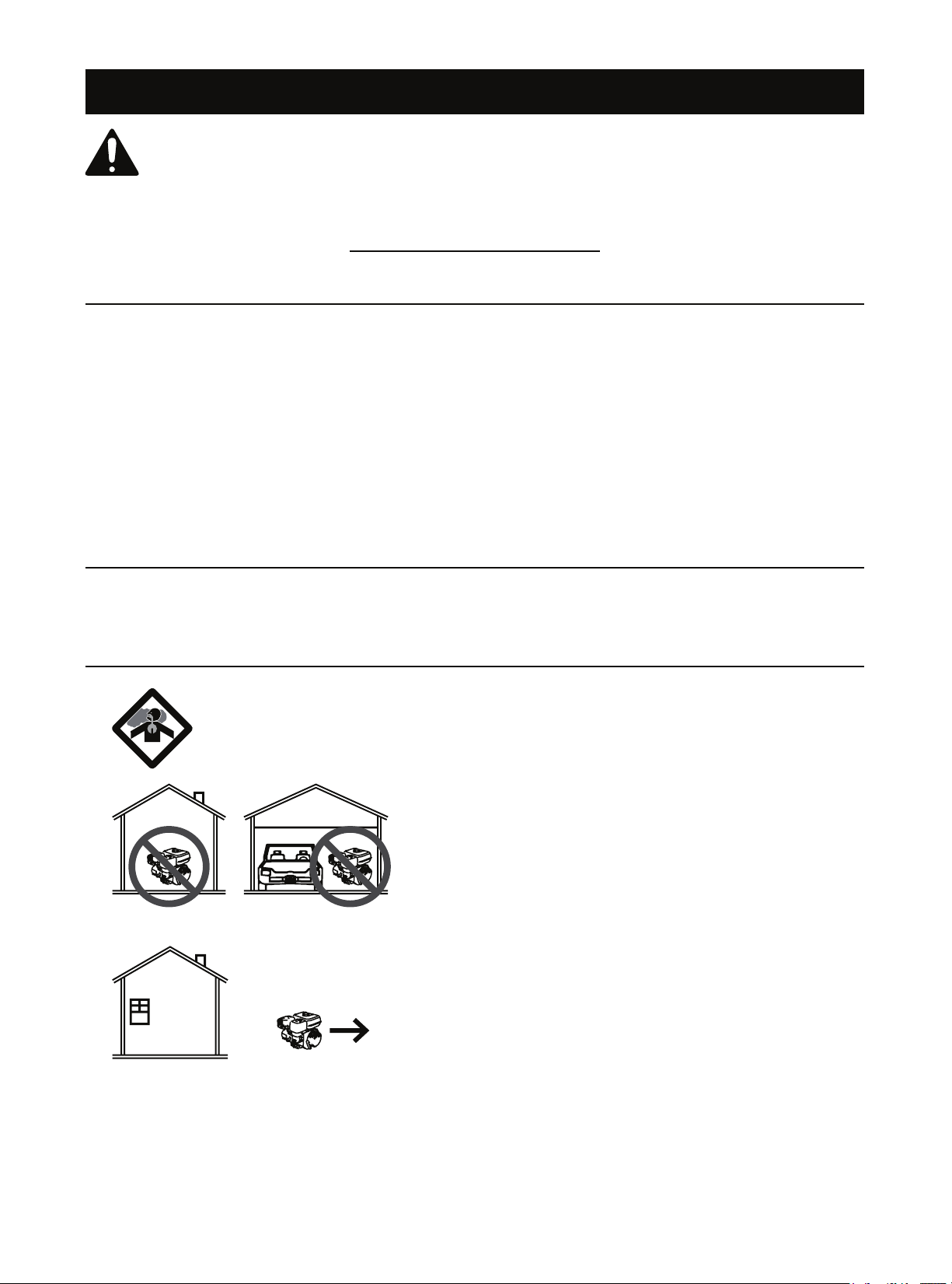
1. CARBON MONOXIDE HAZARD
Using an engine indoors CAN KILL
YOU IN MINUTES.
Engine exhaust contains carbon
monoxide. This is a poison you cannot
see or smell.
NEVER use inside a home or garage,
EVEN IF doors and windows are open.
Only use OUTSIDE and far away from windows,
doors, and vents.
2. Keep children away from the equipment,
especially while it is operating.
3. Do not leave the equipment unattended when it is
running. Turn off the equipment (and remove safety
keys, if available) before leaving the work area.
4. Wear ANSI-approved safety glasses, hearing
protection, and NIOSH-approved dust mask/
respirator under a full face shield during use.
5. Wear heavy-duty work gloves
when handling the blade.
6. People with pacemakers should consult their
physician(s) before use. Electromagnetic
¿HOGVLQFORVHSUR[LPLW\WRDKHDUWSDFHPDNHU
could cause pacemaker interference or
pacemaker failure. Caution is necessary when
near the engine's magneto or recoil starter.
7. Use only accessories that are recommended
by Harbor Freight Tools for your model.
Accessories that may be suitable for one
piece of equipment may become hazardous
when used on another piece of equipment.
SAFETYOPERATIONMAINTENANCE ASSEMBLY

Page 4
8. Do not operate in explosive atmospheres,
VXFKDVLQWKHSUHVHQFHRIÀDPPDEOH
liquids, gases, or dust. Gasoline-powered
engines may ignite the dust or fumes.
9. Stay alert, watch what you are doing and
use common sense when operating this
piece of equipment. Do not use this piece of
HTXLSPHQWZKLOHWLUHGRUXQGHUWKHLQÀXHQFH
of drugs, alcohol or medication.
10. Do not overreach. Keep proper footing and
balance at all times. This enables better control
of the equipment in unexpected situations.
11. Dress properly. Do not wear loose clothing
or jewelry. Keep hair, clothing and gloves away
from moving parts. Loose clothes, jewelry or
long hair can be caught in moving parts.
12. Parts, especially exhaust system components,
get very hot during use. Stay clear of hot parts.
13. Do not cover the engine or
equipment during operation.
14. Keep the equipment, engine, and
surrounding area clean at all times.
15. Use the equipment, accessories, etc., in accordance
with these instructions and in the manner intended for
the particular type of equipment, taking into account
the working conditions and the work to be performed.
Use of the equipment for operations different from
those intended could result in a hazardous situation.
16. Do not operate the equipment with known
leaks in the engine's fuel system.
17. WARNING: The brass components of
this product contain lead, a chemical
known to the State of California to cause
birth defects (or other reproductive harm).
(California Health & Safety code § 25249.5, et seq.)
18. WARNING: Some dust created by power sanding,
sawing, grinding, drilling, and other construction
activities, contains chemicals known [to the State
of California] to cause cancer, birth defects or
other reproductive harm. Some examples of these
chemicals are:
/HDGIURPOHDGEDVHGSDLQWV
&U\VWDOOLQHVLOLFDIURPEULFNVDQGFHPHQWRU
other masonry products
$UVHQLFDQGFKURPLXPIURP
chemically treated lumber
Your risk from these exposures varies, depending
on how often you do this type of work. To reduce
your exposure to these chemicals: work in a well
ventilated area, and work with approved safety
equipment, such as those dust masks that are
VSHFLDOO\GHVLJQHGWR¿OWHURXWPLFURVFRSLFSDUWLFOHV
(California Health & Safety Code § 25249.5, et seq.)
19. This product contains or, when used, produces a
chemical known to the State of California to cause
cancer and birth defects or other reproductive harm.
(California Health & Safety Code § 25249.5, et seq.)
20. When spills of fuel or oil occur, they must be
FOHDQHGXSLPPHGLDWHO\'LVSRVHRIÀXLGVDQG
cleaning materials as per any local, state, or
federal codes and regulations. Store oil rags in
a bottom-ventilated, covered, metal container.
21. Keep hands and feet away from moving parts.
Do not reach over or across
equipment while operating.
22. Before use, check for misalignment or binding
of moving parts, breakage of parts, and any
other condition that may affect the equipment's
operation. If damaged, have the equipment
serviced before using. Many accidents are
caused by poorly maintained equipment.
23. Use the correct equipment for the application.
Do not modify the equipment and do not use the
equipment for a purpose for which it is not intended.
SAFETY OPERATION MAINTENANCEASSEMBLY

Page 5
Service Precautions
1. Before service, maintenance, or cleaning:
a. Turn the engine switch to its “OFF” position.
b. Allow the engine to completely cool.
c. Then, remove the spark plug wire(s)
from the spark plug(s).
2. Keep all safety guards in place and in
proper working order. Safety guards include
PXIÀHUDLUFOHDQHUPHFKDQLFDOJXDUGV
and heat shields, among other guards.
3. Do not alter or adjust any part of the
equipment or its engine that is sealed by the
PDQXIDFWXUHURUGLVWULEXWRU2QO\DTXDOL¿HG
service technician may adjust parts that may
increase or decrease governed engine speed.
4. Wear ANSI-approved safety goggles, heavy-duty
work gloves, and dust mask/respirator during service.
5. Maintain labels and nameplates on the equipment.
These carry important information.
If unreadable or missing, contact
Harbor Freight Tools for a replacement.
6. +DYHWKHHTXLSPHQWVHUYLFHGE\DTXDOL¿HGUHSDLU
person using only identical replacement parts.
This will ensure that the safety of the equipment
is maintained. Do not attempt any service or
maintenance procedures not explained in this
manual or any procedures that you are uncertain
about your ability to perform safely or correctly.
7. Store equipment out of the reach of children.
8. Follow scheduled engine and
equipment maintenance.
9. Refueling:
a. 'RQRWVPRNHRUDOORZVSDUNVÀDPHV
or other sources of ignition around the
equipment, especially when refuelling.
b. 'RQRWUH¿OOWKHIXHOWDQNZKLOHWKH
engine is running or hot.
c. 'RQRW¿OOIXHOWDQNWRWKHWRS/HDYHDOLWWOH
room for the fuel to expand as needed.
d. Refuel in a well-ventilated area only.
SAVE THESE INSTRUCTIONS.

Page 6
6SHFL¿FDWLRQV
Fuel Type 87+ octane unleaded
gasoline
Capacity 1 Gallon
Coolant Tank Capacity 4.2 Quarts
Blade Speed 3,279 FPM
Log Diameter Ǝ0D[LPXP
Board Width Ǝ0D[LPXP
Cutting Thickness Ǝ0D[LPXP
Cutting Length ƍƎ0D[LPXPƎ
Note: (QJLQHVSHFL¿FDWLRQVDUHIRXQGLQWKH
engine manual supplied with this equipment.
Assembly
Read the ENTIRE IMPORTANT SAFETY INFORMATION section at the beginning of this manual
including all text under subheadings therein before set up or use of this product.
TO PREVENT SERIOUS INJURY:
Operate only with proper spark arrestor installed. Operation of this equipment may create sparks that can
VWDUW¿UHVDURXQGGU\YHJHWDWLRQ$VSDUNDUUHVWRUPD\EHUHTXLUHG
7KHRSHUDWRUVKRXOGFRQWDFWORFDO¿UHDJHQFLHVIRUODZVRU
UHJXODWLRQVUHODWLQJWR¿UHSUHYHQWLRQUHTXLUHPHQWV
TO PREVENT SERIOUS INJURY: The Saw Mill is dangerous when assembled incorrectly.
,I\RXGRQRWIHHOFRPSOHWHO\FRPIRUWDEOHDVVHPEOLQJLWWKHQKDYHDTXDOL¿HGWHFKQLFLDQDVVHPEOHLW
Note: For additional information regarding
the parts listed, refer to Assembly Diagram
near the end of this manual.
1. Secure Wheels (1) onto Right Wheel Frame (7a)
with two Hex Bolts M20x100 (6) and Hex Nuts
M20 (2). Attach Right Wheel Frame, Round
Post (20) and the Round Clamp (10) with two
Hex Bolts M12x80 (8) and Hex Nuts M12 (9).
Note: Do not tighten Bolts (8) and Nuts (9).
1
7a
6, 2
20
10
8, 9
Figure A: Right Wheel Frame
2. Secure Wheels (1) onto Left Wheel Frame (3a)
with two Hex Bolts M20x100 (6) and Hex
Nuts M20 (2). Then attach Left Wheel Frame,
Square Post (48) and Square Clamp (4)
with two Hex Bolts (58) and Hex Nuts (5).
Note: Do not tighten Bolts (58) and Nuts (5).
Figure B: Left Wheel Frame
1
3a
6, 2
48
4
58, 5
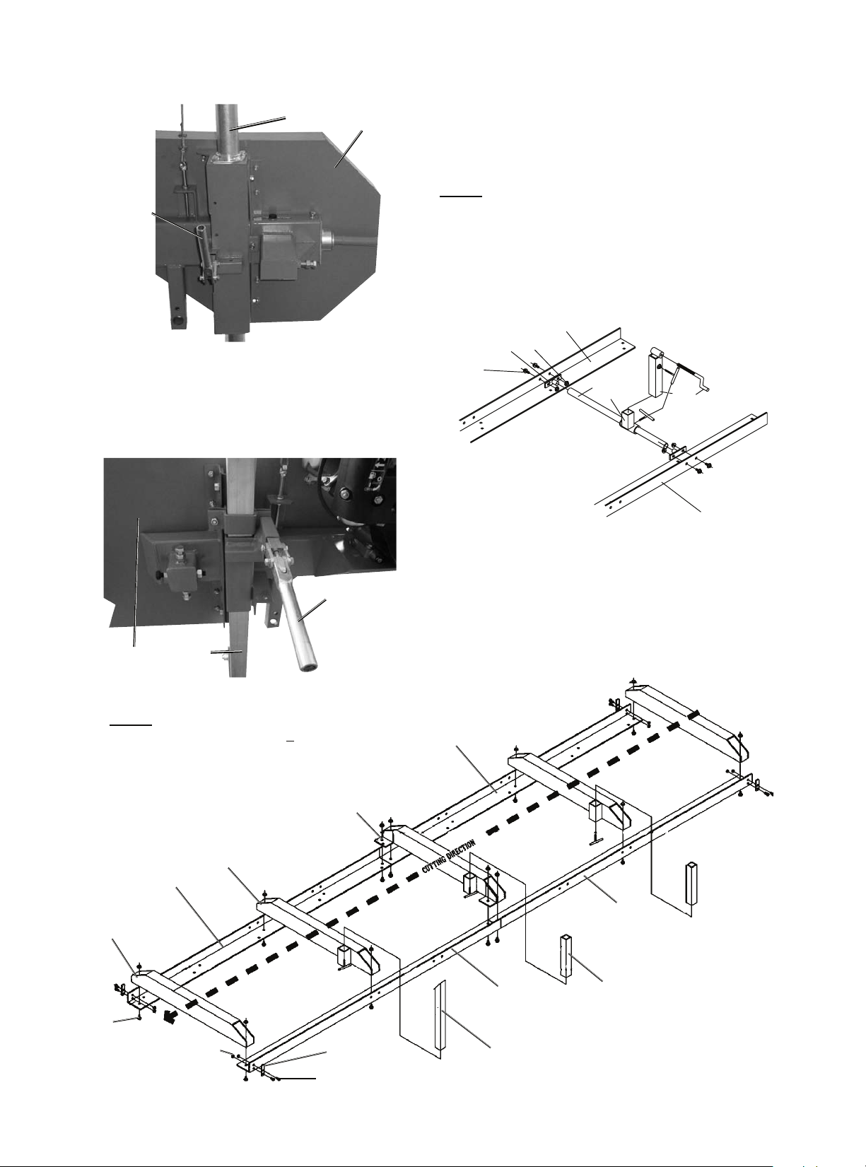
3. Slide the Round Post (20) into the Blade Guard (50),
as shown below. Adjust the bolts until Blade Guard
SAFETY OPERATION MAINTENANCEASSEMBLY
Page 7
can move smoothly on the round post. Then secure
it in place with the Right Lock Handle (59).
Figure C: Right Lock Handle
Blade
Guard
(50)
Right
Lock
Handle
(59)
Round Post (20)
4. Slide the Square Post (48) into the Blade Guard,
as shown below. Adjust the bolts until it can
move smoothly on the square post. Then secure
it in place with the Left Lock Handle (54).
Figure D: Left Lock Handle
Blade
Guard (50)
Left Lock
Handle (54)
Square
Post
(48)
5. Lay out the Track sections (78, 92) as shown below.
6. Use the Bolts (22) and Nuts (25) to fasten the End
Stops (79) to the Track Sections, as shown below.
7. Use the Flange Bolts (77) and Flange
Nuts (84) to fasten the Center Support (90a)
and Middle Supports (81a) to the Track
Sections (78, 92), as shown below.
NOTE: The Track (78) and Track (92) must be aligned
not only on the top surface, but also on the side surface.
The gap between these two parts must be small.
If the top surface of the Tracks are not aligned, use
DJULQGHURU¿OHQRWLQFOXGHGWRVPRRWKWKHPRXW
8. Install the Rocker Tube (88) and Round
Tube (85) assembly as shown below.
Figure F: Rocker Tube
77
78
92
83 84
85
86a
87 89
88
9. Place the carriage onto the track.
Figure E: Track Assembly
NOTE: After assembly, the central distance
RIWKH7UDFNPXVWEHƎ+Ǝ
80a
77
78
79
81a
82
92
78
90a
91
92
Saw mill
¿QLVKHVFXW
at this end.
Saw mill
starts cut from
this end.
22
25
Page 8
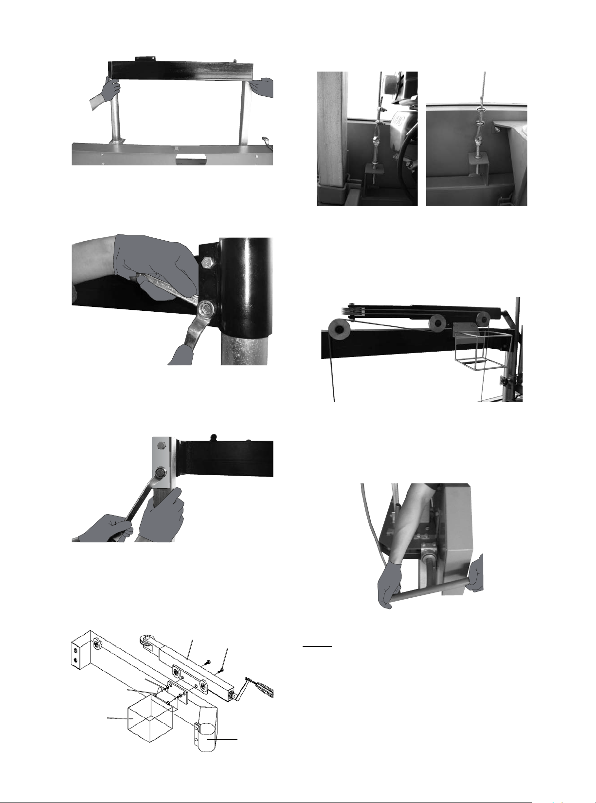
10. Place the Top Frame (23) on the Posts (20, 48).
Figure G: Top Frame
11. Secure the two Bolts (22) attaching
the Top Frame (23) to the
Round Post (20) as shown below.
Figure H: Top Frame Bolts
12. Attach the Top Frame (23) to the
Square Post (48) using the Bolts (49) and
Top Frame Brace (101) as shown below.
Figure I: Top Frame Bolts 2
13. Tighten the Bolts (8,58) and Nuts (5,9).
14. Attach the External Tube (34) and the Water Tank
Tray (45) to the Top Frame (23) using the Bolts (44),
Spring Washer (98), and Nut (99), as shown below.
44
34
23
45
98
99
15. Thread the Cable Anchor Bolts (46) into
the Blade Guard (50) as shown below.
Figure K: Cable Anchor Bolt Locations
16. Route Cables as shown below.
Hook the loops around the two posts on the
back of the External Tube (34). The lower cable
attaches to the lower post. Adjust the Cable
Anchor Bolts (46) until the two cables are equal.
Figure L: Cable Route
17. Loosen the Bolt (70) and the Fixed Block (71) to
move the Fixed Block away from the Blade. Rotate
the Tension Handle (14) in a clockwise direction
to properly tension the Blade, as shown below.
Figure M: Tension Handle
NOTE: Pull up on Blade at Center Guard.
$OORZIRUQRPRUHWKDQƎƎ
movement up or down (“give”) on the Blade.
7KHƎƎJLYHLQGLFDWHVSURSHU%ODGHWHQVLRQ
SAFETY OPERATION MAINTENANCEASSEMBLY

Page 9
18. Slide Fixed Block until it gently touches the Blade.
Then tighten the Bolt, fastening it in place.
See below. Repeat for the remaining Fixed
%ORFNVXQWLOWKHUHLVƎƎFOHDUDQFH
between Fixed Blocks and Blade.
Figure N: Fixed Block and Manual Rotation
Fixed Block (71) Bolt (70)
19. Rotate the Bandwheel (66) slowly
counterclockwise, watching relative position of
the Blade (69) and the Bandwheels (66).
20. If the Blade stays centered on the wheels, tighten
the lock nuts shown on Figure O. If the Blade
does not stay centered, adjust the bolts shown
on Figure O slightly and then rotate the belt
wheel again. See instructions that follow.
GAB
E
F
C
D
adjusting boltadjusting lock nut
Figure O: Adjustment Bolts
NOTE: Adjust Blade again after replacement.
Refer to Figure O for the following instructions:
BEFORE any adjustment, loosen Bolts
E and F and Nuts C and D.
If after replacement Blade starts to shift back
towards operator, loosen Nut A and hold Bolt G with
a wrench. Then tighten Nut A after adjustment.
If the Blade shifts back from the operator,
loosen Nut B and hold Bolt G with a wrench.
Then tighten Nut B after Blade adjustment.
Continue making small adjustments until
Blade stays centered, AFTER any adjustment,
tighten Bolts E and F and Nuts C and D.
21. Install Throttle Control (93) on Pushing
Handle (94) as shown below.
Figure P: Throttle Control
22. Lubricate the Round Post (20) and the
Square Post (48) with lithium grease to
allow the sawhead to move smoothly.
23. Install the Water Tank (95) into
the Water Tank Tray (45).
24. Route the Water Tube (97) through the bracket on the
lower right of the Blade Guard (50) Secure in place
with the tip facing the blade using the water tube
holding bolt shown below, but do not overtighten.
Figure Q: Water Tube
Blade
Guard
(50)
lower
right
bracket
Water
Tube (97)
Water Tube
Holding
Bolt
25. For horizontal Blade adjustment, loosen the Nut (47)
and adjust the left and right Lock Handles (54,59)
until the distance between the ends of the Blade and
the top of the Middle Support (81a) are the same.
NOTE: Use a tape measure to verify distances match.
SAFETYOPERATIONMAINTENANCE ASSEMBLY
Page 10
Operating Instructions
Read the ENTIRE IMPORTANT
SAFETY INFORMATION section at the
beginning of this manual including
all text under subheadings therein
before set up or use of this product.
Engine Operation
Inspect engine and equipment looking
for damaged, loose, and missing
parts before set up and starting.
If any problems are found, do not use
HTXLSPHQWXQWLO¿[HGSURSHUO\
Start Procedure
Before starting the engine:
a. Follow the Set Up Instructions to
prepare the equipment. Follow all
instructions in the separate engine
manual provided with the engine.
b. Inspect the equipment and engine.
c. Fill the engine with the proper
amount and type of fuel and oil.
d. Read the Equipment Operation
section that follows.
1. Start and operate the engine according
to the provided engine manual.
2. Replacement engine operating instructions can
be obtained from the engine manufacturer.
Equipment Operation
1. Wear heavy-duty work gloves, ANSI-approved
goggles behind a full face shield, steel-toed
work boots, and a dust mask.
2. Operate only with assistance.
3. Fill the Water Tank with clean water.
4. 7KHPD[LPXPORJGLDPHWHUWKDWFDQEHFXWLVƎ
7KHPD[LPXPERDUGZLGWKWKDWFDQEHFXWLVƎ
7KHOXPEHUPXVWEHDWOHDVWƍƎORQJDQG
must rest on at least two Supports (81a, 90a)
to prevent instability.
5. Cut branches off the lumber to be
processed before milling.
6. WARNING! To prevent death and
serious injury. Do not cut lumber containing
foreign objects (nails, metal, etc.).
7. Choose the Short Log Supports (91) or the Long Log
Supports (82) according to the lumber diameter.
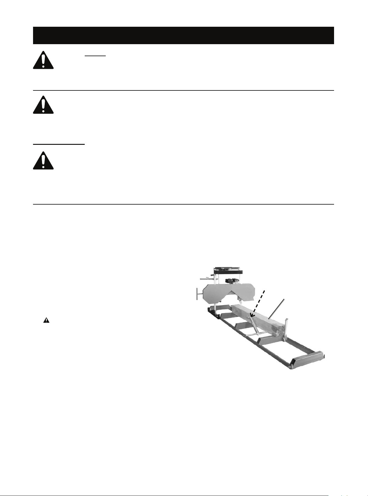
8. Place the lumber to be cut on the Supports.
See picture below. Brace the lumber against
the Log Supports (82, 91) to prevent movement
during milling. The lumber should be positioned so
that the force of cutting holds it against the supports.
Figure R: Lumber Position
Lumber on
Supports
Clamp
Lumber
Here
9. Clamp the lumber in place against the Log
Supports (82, 91) using the Log Clamp (89) in
the location shown above. Position the Log
Clamp is below the level of the blade.
10. Tighten all Bolts and T-Handles on the Log
Clamp (89) and the Log Supports (82, 91). Verify
that they are securely in place before proceeding.
SAFETY OPERATION MAINTENANCEASSEMBLY
Other LOGSMITH Saw manuals


