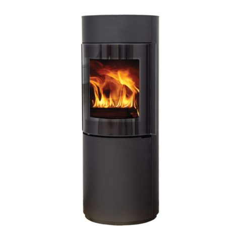
Lokaterm FLORIDA User manual

CREINA d.d, Mirka Vadnova 8, 4000 KRANJ
Tel.: 04 20 13 3 0, Fax: 04 20 13 363, E-mail: INFO@CREINA.SI
www. lokaterm.com, www.creina.si
Installation instruction for FLORIDA Stove

Mounting instructions FLORIDA stove Creina d.d.
INDEX
Technical data.......................................................................................................................3
1. Mounting instructions...........................................................................................................4
1.1. Foreword........................................................................................................................4
1. . Regulations....................................................................................................................4
. Basic requirements...............................................................................................................4
.1. Installation area..............................................................................................................4
2.1.1. Stove can be installed if:.........................................................................................4
2.1.2. Stove must not be installed:....................................................................................4
2.1.3. Installation requirements.........................................................................................4
2.1.4. Air combustion conduit............................................................................................4
2.1.5. Floor protection.......................................................................................................4
2.1.6. Fire protection distances.........................................................................................5
2.1.7. Chimney..................................................................................................................5
3. Transport..............................................................................................................................5
3.1. Packaging......................................................................................................................5
3. . Handling of stove...........................................................................................................5
4. Installation instructions.........................................................................................................5
4.1. General (Air inlet is optional)..........................................................................................5
4. . Air supply connection.....................................................................................................5
4.3. Repair advice.................................................................................................................5
4.4. General warranty............................................................................................................5
V1.0 Lokaterm™ © 08/08 stran

Mounting instructions FLORIDA stove Creina d.d.
Technical data
V1.0 Lokaterm™ © 08/08 stran 3
Model: Type: FLORIDA
Standard: EN 13 40
Chimney connection diameter: Ø 150 mm
Output: 3-8 kW
Nominal output 8 kW
Flue gas temperature (polena): 340 °C
Density of flue gas flow (polena): 6,5 g/s
Flue draught (polena; pri nominalni moči 8 kW): 1 Pa
Air supply connection diameter Ø 100 mm
Weight (netto) cca.150 kg
Stove dimensions: 1111x495x597

Mounting instructions FLORIDA stove Creina d.d.
1. Mounting instructions
1.1. Foreword
Please read these instructions carefully and pay
attention to advices, especially to those for safe
handling.
Before you start with the installation of the stove,
check:
oIf all parts are included (Notify supplier if any of
the parts are missing)
oThe stove for potential damages (pay special
attention to glass, firedoor and coating
protection; Notify hauler, if damages are
found)
oThe functionality of all the movable parts
This manual is not a service handbook. Here
you won't find any instructions on how to repair
the stove.
1.2. Regulations
Following regulations and standards have to be
followed:
oEN 13 40
oState building regulations and provisions.
oFire-protection provisions.
oAll other European, national and local
regulations and provisions that deal with
installation of the stove.
2. Basic requirements
2.1. Installation area
2.1.1. Stove can be installed if:
oInstallation area is big enough to ensure
normal use (operating, cleaning …) of the
stove.
oWithin radiation area of the stove, there are
no load-bearing construction elements (ex.
pillars).
oSufficient air supply is secured.
oThere is at least one door or window that
leads out of the room where the stove is
installed.
oThere is a direct or indirect air connection
with another room.
2.1.2. Stove must not be installed:
oIn rooms, where highly inflammable and
explosive substances or their mixtures are
being manufactured, processed or stored.
oIn rooms that are ventilated and have safety
devices that prevent negative pressure.
oIn rooms that have no adequate air supply for
stove to work properly.
2.1.3. Installation requirements
oStove has to be installed in a way, that
connection parts (chimney flue, air conduit),
when needed of cleaning, are easily
accessible.
oWalls in installation area of the stove, must
be free of electrical and gas installations.
2.1.4. Air combustion conduit
oAir connection for additional air supply to the
room, where stove will be installed, has to
have a cross-section of at least 100 cm .
oFresh air conduit has to have an inbuilt
closing flap, where positions »open« -
»close«, must be clearly visible.
oWhen calculating the necessary air conduit
cross-section, local (elbows, filters etc.) and
line (conduit length) resistances have to be
taken into consideration.
oWhen air travels through operating
combustion chamber, it heats up.
oAir conduit's overflow resistance must not
exceed 4 Pa.
2.1.5. Floor protection
oIf floor, where stove will be located, is not fire
resistant, it has to be protected by a layer of
fire-resistant material (ex. 6 mm thick glass
plate).
oIncombustible floor area in front of the stove
has to be at least 50 cm long, while on the
sides the distance must not be less then 0
cm. (measured from stove walls)
V1.0 Lokaterm™ © 08/08 stran 4

Mounting instructions FLORIDA stove Creina d.d.
2.1.6. Fire protection distances
Minimum distance between charging door and
combustible objects must be at least 80 cm,
while for sideplates; the distance must be
greater then 0 cm.
2.1.7. Chimney
Effective height of the chimney should be at
least 4 meters (measured from the hearth of the
stove). For detailed calculations, please refer to
standard EN 13384-1.
3. Transport
Transport should be handled by experts with
appropriate equipment.
3.1. Packaging
oStove it tightly fixed onto a palette.
oPlease check the stove for possible damages
and that is contains all ordered parts.
oIf you do find any damages, please report
them to your stove supplier immediately.
3.2. Handling of stove
oStoves should be moved with a palette,
standing upside-down. Move it carefully so it
does not tip over!
oAvoid shocks and vibrations.
oOnce in place, dismount it and proceed with
the installation.
oCover of the stove is breakable. It must not be
loaded.
4. Installation instructions
4.1. General (Air inlet is optional)
oPlease do not overload the stove.
oAll the packing material should be removed
from hearth and ash pan.
oCheck out functionality of movable parts (front
door etc.)
oBuild outer air flaps into facade
oMount smoke flap onto chimney funnel
oConnect chimney funnel. Chimney thickness
and insulation must be in accordance with
country's and EU construction regulations.
oChimney must not apply additional pressure
on the stove.
oMinimum diameter of the chimney should be
taken into consideration.
oMeasured values, gathered in this document,
corresponds to the calculations of chimney
with the following dimensions - 4 m height;
diameter 150mm.
4.2. Air supply connection
oFor stove to work properly, continuous air
supply is required.
oIf upper requirement is not met, additional air
supply can be provided through air
connection (Ø100mm) which is located at the
back of the stove.
oAirflow is being regulated with air taps, which
are built-in, into air supply conduit.
oPlease note that during winter times, cold air
surges can generate condense on stove
parts and thus compromise its functionality.
4.3. Repair advice
oGlass frame and most of the movable parts
can be removed once the stove is installed.
oRepairs can only be performed by a
professional in agreement with the
supplier/manufacturer
oRepair instructions are not part of this
document
oIf necessary, refer to your local dealer of
service agent.
4.4. General warranty
General warranty applies. For details, please
look at the user manual.
V1.0 Lokaterm™ © 08/08 stran 5
Table of contents
Other Lokaterm Stove manuals
Popular Stove manuals by other brands

United States Stove
United States Stove ASHLEY AP130 Owner's operation and instruction manual

Premier
Premier ED-4704IC instruction manual

Falcon
Falcon G1478 User instructions

Harman Home Heating
Harman Home Heating DVC-500 Installation & operating manual

DS Stoves
DS Stoves Anthra-Max XV14 owner's manual

Regency
Regency Ultimate U38-LP1 Specification sheet

Empire Comfort Systems
Empire Comfort Systems superb ES-100 Assembly instructions

Lopi
Lopi Stove owner's manual

Stanley
Stanley K1200 instruction manual

FireBird
FireBird Multifuel Backboiler Inset Stove Series instruction manual

Dimplex
Dimplex Piermont PMN20 user manual

Charlton & Jenrick
Charlton & Jenrick Infinity 780 FL Mrk2 owner's manual