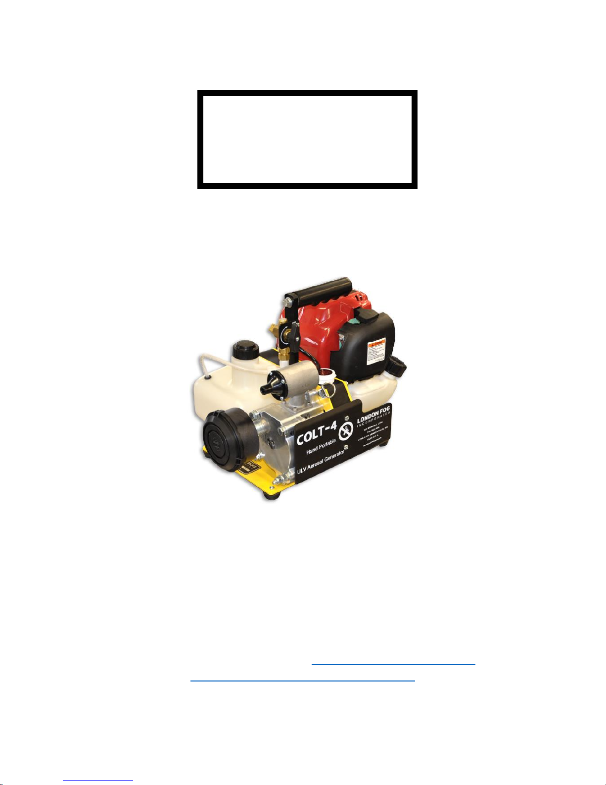
London Fog Colt-4 Use and care manual

1
Jan., 2018 rev.
COLT-4
ULV Handheld Aerosol Generator
- With 4 Cycle Gasoline Engine
OPERATING INSTRUCTIONS
AND
ILLUSTRATED PARTS
CUSTOMER SERVICE –A TRADITION
505 Brimhall Ave PO Box 406 Long Lake, Minnesota 55356
PHONE: (952) 473-5366 www.londonfoggers.com
salessupport@londonfoggers.com

2
LONDON FOGGERS
ONE YEAR LIMITED WARRANTY
LONDON FOG, INC. SUBJECT TO THE PROVISIONS BELOW WARRANT
EACH NEW PRODUCT MANUFACTURED BY THE COMPANY TO BE FREE
FROM DEFECTS IN MATERIAL AND/OR WORKMANSHIP IN NORMAL
SERVICE FOR THE PERIOD ON ONE (1) YEAR COMMENCING WITH
DELIVERY OF THE MACHINE TO THE ORIGINAL USER.
The obligation under this warranty is expressly limited to the replacement or
repair, at the Company’s option, at the plant of LONDON FOG, INC., Long Lake
Minnesota or at a service facility designated by the company, of such part or
parts as inspection shall disclose to have been defective. This warranty does not
apply to defects caused or unreasonable use (including failure to provide
reasonable and necessary maintenance) while in the possession of the user.
LONDON FOG, INC. SHALL NOT BE LIABLE FOR COLLATERAL, INDIRECT,
INCIDENTAL OR CONSEQUENTIAL DAMAGES OF ANY KIND, including but
not limited to, consequential labor costs or transportation charges in connection
with the replacement or repair of defective parts or machines. The user assumes
all liability for any damage of any kind which may result from its use or misuse by
any employees, agents, persons or third parties unknown to Company or User.
All warranties, express, or implied, including any warranty created or established
by statutory law or operation of law, are deemed null and void in the event that a
product has been physically modified in any manner by the use, or any person or
party other than the company.
The company makes no warranty with respect to engines, air pumps, blowers
and products distributed by Company. Those parts and products are subject to
warranties of their respective manufacturers.
THE WARRANTY EXPRESSED IN LIEU OF ALL OTHER WARRANTIES,
EXPRESSED OR IMPLIED, STATUTORY OR OTHERWISE, INCLUDING ANY
IMPLIED WARRANTY OF, MERCHANTABILITY OR FITNESS FOR A
PARTICULAR PURPOSE. NO WARRANTIES ARE EXPRESSED OR IMPLIED
WHICH EXTEND BEYOND THE DESCRIPTION CONTAINED IN THIS
WRITTEN WARRANTY AND NO ONE IS AUTHORIZED TO MODIFY THIS
WRITTEN WARRANTY.
CUSTOMER SERVICE - A TRADITION

3
Specifications Colt-4:
Engine: Air Cooled, 4 stroke single cylinder, regular gasoline only
Fuel Tank: 20 Ounces, (.65 liters) 35-45 minute run time
Compressor: Rotary Vane, Oil-less, 100% ball and roller bearing, graphite
air fins
Formulation Tank: One Quart, 32 ounces (.946 liters)
Formulation Output: Siphon Nozzle with 3 orifice discs included
Formula Metering: 1-4 ounce orifice discs included
Particle Size: 80% less than 20 microns
Weight: 20 lbs dry (9.2 kg)
Length: 14 in. (35.6cm)
Width: 11.5 in. (28.2cm)
Height: 13.5 in. (34.3cm)

4
PRE-START CHECKLIST
All safety equipment is in place _____
Sufficient gasoline in gas tank _____
Oil in engine at proper level _____
All fluid lines tight and connected _____
Sufficient formulation in tank _____
Flow rate is calibrated _____
Nozzle is aimed properly _____
Spray switch is in OFF position _____
CAUTION
Before proceeding with any spraying operation, the operator should be thoroughly
familiar with starting and stopping the machine and with all the operating controls. If you
are operating the machine for the first time, exercise the machine through its full
operational sequences from a position of full visibility of the machine before operating
the machine fully remote. This is also a good idea for experienced operators who may
be operating a new machine or who may be reactivating a machine after repairs or a
period of inactivity. Refer to the operation section for starting and stopping instructions.

5
COLT-4 Quick Start Checklist
A. Engine
1) Please check oil level in Colt-4 Honda engine with indicator in dipstick
before each use
2) Engine is a 4 cycle engine, and thus uses only STRAIGHT GASOLINE,
please do NOT mix any oil with the gasoline.
3) Oil is 10-30 oil
4) Make sure RED on off button is in the ON position before starting, and
red choke lever is used during warm up only
B. Compressor
1) Please change compressor filter when it is no longer "orange looking",
but turns brown which is an indication of clogged filtration
C. Chemical flow
1) After starting the engine, turn the spray on/off lever to ON to begin the
siphon from the tank, please turn the spray knob to the OFF position to stop
spray and "clear out the filter" of any remaining chemical in the lines. (see
page 4 language from the manual below)
2) The Colt -4 comes with 4 orifice disc's for various flow. The 1 ounce
per minute disc (#16 disc is imprinted on the orifice disc) is in the machine
when shipping from the factory. Also included are #22 (1.5 ozs. per minute),
#24 discs (2 ozs. per minute).
From Page 4 in the manual:
Rate of formulation flow is controlled by the orifice disc which is located in the
small hex nut chamber screwed into the valve body, which is directly under the
aerosol control valve. An orifice that gives approximately 1 Oz/Min (#16) flow rate
with petroleum distillate base materials comes installed in the unit. 1 1/2 Oz/Min
(#22) and 2 Oz/Min (#24) orifice discs are located in the round, white plastic
container located on the top of the belt guard, just behind the nozzle. Additional
discs for other flow rates are available. Using a larger orifice size will increase the
formulation flow rate or keep the flow rate the same when using a more viscous
material.
"Spray at dawn or dusk when mosquitoes are most active."
"Always refer to the insecticide label for mixing instructions."
"Always turn off the aerosol before stopping the engine."

6
OPERATING INSTRUCTIONS
I. SAFETY PRECAUTIONS
A. Observe all precautions on the registration and any other labels of
the insecticide being used. Do not handle London Fog machine
parts which come in contact with the insecticide until the machine
has first been thoroughly flushed and the parts have been cleaned
while observing label recommended cautions.
B. Never fill the gasoline tank when the engine is running, or hot from
running. Gasoline spilled on hot engine parts may cause a fire or
explosion.
C. An approved respirator mask must be worn by all personnel
exposed to the aerosol.
D. Never leave a hot unit indoors. Allow it to cool off outdoors before
transporting or storing.
E. Never run engine in enclosed, poorly ventilated areas. Engine
exhaust gases contain carbon monoxide, an odorless and deadly
gas.
IN NO WAY IS IT TO BE CONSTRUED THAT THE CHEMICALS AND/OR
DOSAGES ARE THE RECOMMENDATION OF LONDON FOG, INC.
LONDON FOG, INC. SHALL IN NO EVENT BE LIABLE FOR CONSEQUENTIAL
DAMAGES OR CONTINGENT LIABILITIES ARISING OUT OF THE FAILURE
OF ANY AEROSOL GENERATOR OR PART TO OPERATE PROPERLY.

7
OPERATING INSTRUCTIONS (continued)
II. SERVICE BEFORE START-UP
Engine Prestart Preparations
ENGINE OIL LEVEL
BEFORE EACH USE check the oil as follows:
A. Make sure the engine is stopped and resting on a level surface. Also
make sure the engine is cool and the oil has had time to drain into the
sump.
B. Clean the area around the dipstick and filler cap to keep dirt and debris
out of the engine.
C. Remove the dipstick and wipe oil off. Reinsert the dipstick and push it all
the way down into tube. Remove the dipstick and check the level.
D. Add the proper type of oil if the level is low. Bring the level up to, but not
over, the "F" mark on the dipstick before adding more oil.
CAUTION:
DO NOT operate the engine with the oil level
below "L" mark or over "F" mark.
* Check engine oil, fill the "F" mark on dipstick as opposed to adding a given
quantity of oil. Always check level on dipstick before starting, or adding
more oil.
Colt engine is a 4 stroke engine. It does NOT require mixing of oil and gas.
Please fill gasoline tank with 87 octane (non ethanol) fuel only.
FILL FUEL TANK with fuel as specified in preceding instructions.
Remove fuel fill cap and place it on a clean surface.

8
OPERATING INSTRUCTIONS (continued)
NEVER FILL FUEL TANK INDOORS, WITH ENGINE RUNNING OR
WHILE ENGINE IS HOT.
NEVER FILL FUEL TANK COMPLETELY. FILL TANK TO WITHIN 1/4
TO 1/2 INCH OF TOP OF TANK TO PROVIDE SPACE FOR FUEL
EXPANSION. WIPE ANY FUEL SPILLAGE FORM ENGINE AND
EQUIPMENT BEFORE STARTING ENGINE.
CHECK THE FOLLOWING before attempting to start your engine:
Be sure ignition switch located on the top of the engine is in the
ON position.
III. OPERATION
A. FORMULATION
1. Unscrew the bottle cap from the formulation bottle
2. Service the formulation bottle with the proper insecticide
formulation and turn the bottle cap tight.
B. ENGINE: Subaru Robin 4 cycle
(1) COLD ENGINE START (Engine has not been run recently)
1. Push Primer Bulb 6-8 times. Pull starter handle with a
smooth rapid movement; rewind smoothly. Do not allow
rope to snap back.
2. If engine fires but does not start, push primer bulb 2-3
additional times and pull starter handle until engine starts.
(2) WARM ENGINE START (Engine has been run recently)
1. Pull starter handle until engine starts. If engine fails to start
after several attempts, follow preceding "Cold Engine Start"
instructions.
TO STOP ENGINE
To STOP the engine, move ignition switch to the OFF position.

9
OPERATING INSTRUCTIONS
(continued)
C. AEROSOL OPERATING INSTRUCTIONS
1. Use only insecticide formulation labeled for ground ULV
application and supplied by a reputable dealer or distributor.
2. In order to obtain the best aerosol quality, allow engine and
compressor to run until the engine is warmed up before turning the
aerosol ON.
3. With machine running, the aerosol is turned ON by rotating
the valve 180 degrees counterclockwise. Rotating the valve
180 degrees clockwise turns the aerosol OFF. With the
addition of the new 3-way ball valve there is a 6-10 second
delay before spray begins.
4. Rate of formulation flow is controlled by the orifice disc
which is located in the small hex nut chamber screwed into
the valve body, which is directly under the aerosol control
valve. An orifice that gives approximately 1 Oz/Min (#16)
flow rate with petroleum distillate base materials comes
installed in the unit. 1 1/2 Oz/Min (#22) and 2 Oz/Min (#24)
orifice discs are located in the round, white plastic container
located on the top of the belt guard, just behind the nozzle.
Additional discs for other flow rates are available upon
specific requests.
5. Using a larger orifice size will increase the formulation flow
rate or keep the flow rate the same when using a more
viscous material.
6. Always turn off the aerosol before stopping the engine.
IV APPLICATION INSTRUCTIONS
A. GENERAL INSTRUCTIONS
1. Read and understand chemical labels and instructions.
2. Use only chemicals that are labeled for ground ULV
application.
3. Always use a respirator that is adequate for the chemical
and particle size being aerosolized.

10
OPERATING INSTRUCTIONS
(continued)
B. INDOOR APPLICATION
1. It is a good practice to remove all pets and animals when
possible. Fish bowls and aquariums should be removed or
covered. The air supply to aquariums should be turned off.
2. Shut off the area to be treated as tightly as possible. Close
all doors and windows. Turn off ventilators, fans, air
conditioners. Leave off for a minimum of 1 hour after
treatment.
3. For best results, interior doors, cabinets, etc. should be left
open. Open food containers should be sealed.
4. While the possibility of explosion is remote, good
application practice requires the extinguishing of open
flames, pilot lights, etc. Electricity should be turned off.
5. All food stuffs, plants, surfaces or other items that could be
affected by insecticide should be removed, covered or
sealed.
6. Always stay with the equipment when in operation. Never
leave the machine unattended.
7. Know the formulation application rate and the time required
to treat the area. Walk leisurely through the area timing
your application. Start at the furthest point from the exit and
work toward it. This should minimize your exposure to the
insecticide.
8. Keep the nozzle at least 3 feet from any target at all times.
Short direct shots to known or suspected trouble areas are
an acceptable practice and should not leave an oil residue
on the target.
9. Allow the aerosol to stand as long as possible before
opening and ventilating the treated area. Let stand 1 hour
as an absolute minimum with 2-6 hours being preferred.
10. A typical flow rate is approximately 1 oz. of formulation per
minute. To determine the application time, first determine
the total amount of formulation to be used:

11
OPERATING INSTRUCTIONS
(continued)
(cu.ft. of area to be treated) (oz. of formulation req'd per 1000 cu.ft.)= oz.
of formulation 1000
oz. of formulation = application time in minutes
calibrated flow rate in oz./min.
Example: A 50,000 cu. ft. area is to be treated using 1/4 oz. of
formulation per 1000 cu. ft.
(50,000 cu. ft.) (.25 oz/1000 cu.ft.) - 12.5 oz. of formulation
1000
C. CALIBRATION
Since the nozzle used is an external mix siphon (suction) type
nozzle, calibration must be made with the machine running.
1. Carefully remove the pickup tube from the formulation tank
by pulling it straight up and out of the tank. Place the P/U
tube in a graduated beaker.
2. With the machine running, using a stopwatch and
graduated beaker, measure the flow for (1) minute and
note the amount of fluid used.
Care should be taken not to have the graduated beaker
higher than the top of the formulation tank, or lower than the
bottom of the formulation, as this will affect the accuracy of
the calibration.
NOTE: If the beaker size permits, use a 2 or 3 minute sample for
better accuracy. Just divide the total amount used by 2 or 3
(the actual time) to get a one minute reading divide ML by
29.57 to get ounces. To change flow rate install a larger or
smaller orifice provided with the machine. Repeat the
calibration.

12
OPERATING INSTRUCTIONS
(continued)
D. OUTDOOR APPLICATIONS
1. Areas around homes, picnic areas, swimming pools, etc.
a. Best results are obtained in the cooler hours of early
morning or evening when the insects are most active.
Ideal wind speed is between 3-7 mph. If wind speed
exceeds 10 mph., it is not recommended to disperse
insecticide.
b. Start upwind of the area to be treated and walk at a
leisurely pace (2 mph). Keep the nozzle downwind
and about waist high.
c. If your desired application rate is about 1 oz. per
acre, set your flow rate to approximately 1 oz/min.
Assuming an application swath of 125 ft., and
walking at 2 mph, you should cover approximately
1/2 acre per minute. If using a flow rate of 2 oz/min,
walk briskly (approx. 4 mph) and you will cover 1
acre per minute.
d. If the area to be treated is over 125 ft. deep, move
downwind approximately 50-75 ft. on each
successive pass.
CAUTION An approved respirator mask must be worn by all personnel
exposed to the aerosol.
V. FLUSHING
Depending upon the insecticide used, it may be desirable to flush out the
insecticide system by running a suitable flushing agent through the
machine after each use. Kerosene or fuel oil is recommended for
flushing.
CAUTION An approved respirator mask must be worn by all personnel
exposed to the aerosol.

13
OPERATING INSTRUCTIONS
(continued)
VI PREPARATION FOR STORAGE
A. MACHINE
Prepare unit for storage by draining all the formulation from the
container. Then partially fill container with range oil (#1 fuel oil),
kerosene or de-odorized kerosene, or mineral oil. Flush
system by operating unit until the above base oil is consumed.
Finally drain any remaining base oil from the container. Drain fuel or run
dry gasoline tank. All tanks should be run dry. Clean filter located
attached to On/Off handle, and inspect. Replace is necessary.
EXPLODED VIEW, COLT

14
Colt PN # 4-1000
Balloon Number
Part Number
1
Blower Complete w filter w pulley w nozzle
4-200
2
Blower Filter Assy
4-208
3
Blower Pully
4-274
4
Blower Nozzle
4-303
5
Blower Nozzle tip
4-302
6
Formulation Tank complete with cap and 1/4 in. OD hose
4-700
7
Spray On Off assy Complete
4-650
8
Orafice Discs (qty 3, #16 disc - #22 disc - #24 disc)
4-663
9
Aluminium Handle Mount
4-405
10
Handle Assy Grip Complete
4-406
11
Engine Pulley only (no adaptor)
4-102
12
Crankshaft Adaptor Extension
4-104
13
Honda 4 cycle engine 50cc no pulley no adaptor
4-101
14
Sheetmetal base Blower with rubber feet
4-411
15
Sheetmetal base Engine with rubber feet
4-412
16
Belt guard surround complete
4-410
17
One Year Spare Parts Kit
4-1001
18
Two Year Spare Parts Kit
4-1002
19
Drive Belt
4-203
20
Carry Strap (not pictured)
4-671

15
ORIFICE DISC CHART
(see item #8 on Exploded View, Prev Page for orifice location)
NOTE: To order replacement orifices or orifices not listed, use part number # 4-
663 for kit of 3 replacement discs.
*Chemical formulations with “thin” viscosity carrier oils such as
kerosene, mineral oil, diluent oils, Etc.
* Oz/Min Orifice Disc #
1 …………. 16
1.5 …………. 22
2 …………. 24
Discs Included with Machine 16,22,24
Disc Installed with machine at factory: #16
Part Number for 3 replacement discs #4-663
*These are approximate settings. Always calibrate in order to
obtain true flow rates.
Table of contents
Popular Portable Generator manuals by other brands

King Canada
King Canada 1500W Gasoline Generator KCG-1500G instruction manual

Impax
Impax IM3000IFG manual

Mase Generators
Mase Generators MPF 33-44 Use and maintenance manual

Husqvarna
Husqvarna 1055 GN Operator's manual

Crystal Vision
Crystal Vision Indigo REFGEN user manual

AccuPel
AccuPel HDG-4000 user manual