Lotek SRX1200 Series User manual

USER MANUAL
REVISION 01
07 FEB 2023
#MVHF019
SRX1200 Remote
Connectivity Manual

1
TABLE OF CONTENTS
1. INTRODUCTION .................................................................................................................................... 2
2. EQUIPMENT NEEDED........................................................................................................................ 2
3. CONNECTIONS.......................................................................................................................................3
4. CELL MODEM CONFIGURATION...................................................................................................3
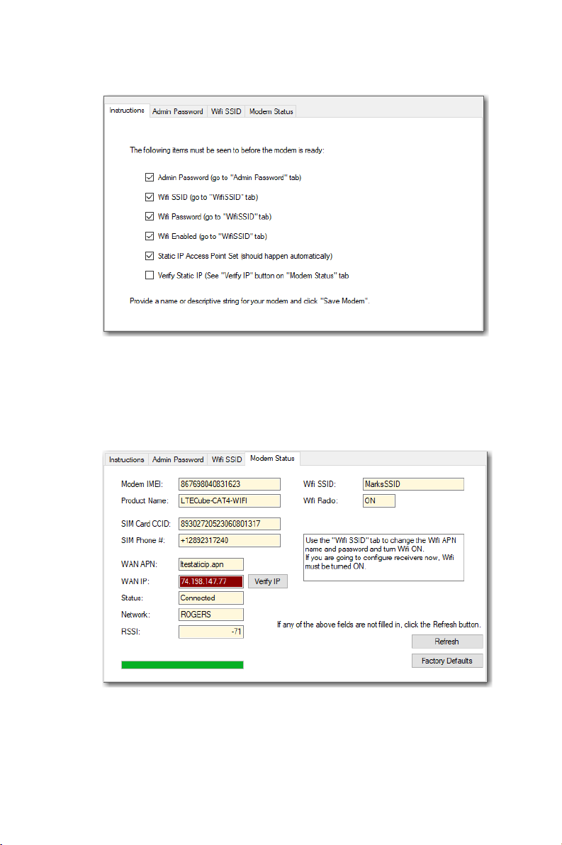
4.1. INITIAL CONFIGURATION OF CELL MODEM.................................................................. 4
4.2. CELL MODEM CONFIGURATION IN HOST........................................................................7
5. CONNECTING SRX1200 RECEIVERS TO THE CELL MODEM .........................................11
5.1. CONNECT TO MODEM ACCESS POINT............................................................................13
5.2. MODEM RULES, PORT FORWARDING AND FIREWALL..........................................14
5.2.1. CONNECTIONS .....................................................................................................................15
5.2.2. ASSIGN A FIXED LOCAL IP..............................................................................................15
5.2.3. CREATE A PORT FORWARDING RULE.....................................................................16
5.2.4. CREATE A FIREWALL RULE............................................................................................16
5.2.5. CONNECTING ADDITIONAL RECEIVERS ................................................................17
6. CONNECTING TO RECEIVERS REMOTELY.............................................................................18
6.1. REMOTE DEVICE PANEL .........................................................................................................18
6.1.1. CLOSING THE CONNECTION.........................................................................................21
6.1.2. ADD A NEW IP AND PORT..............................................................................................21
APPENDIX 1: CONNECTING A RECEIVER CHECKLIST ............................................................ 23
CONTACT INFORMATION......................................................................................................................25
CUSTOMER SUPPORT ........................................................................................................................25

2
1. Introduction
Thank you for purchasing the SRX1200 receiver. This document will help you set
up your receiver unit with the Microhard LTECUBE CAT4-Wifi Cellular Modem.
•The global version (LTECube-CAT4GL-WIFI) may be used anywhere.
•The North American version (LTECube-CAT4NA2-WIFI) may be used
only in North America.
2. Equipment Needed
You will need the following:
•1 Microhard LTECUBE CAT4-Wifi Modem
oList level 2 - 1.26 The cell modem must have a SIM card installed
that has been configured by the carrier to have a static IP address.
oThe static IP address is, supplied by the provider.
•1 Ethernet cable
•One (or more) SRX1200 receiver(s) to be set up.
Note: Only SRX1200-MD2 and SRX1200-D2 models are compatible for
remote connectivity. If you have a different model, and wish to
upgrade, please contact your Lotek representative.
•A USB-A to USB-B cable
•A Windows PC with the latest SRX1200 Host (henceforth known as
Host) installed.

3
3. Connections
To perform the setup, ensure that the following connections are made:
1. Connect the Microhard Cellular modem to the power cable provided
and connect this to a 120VAC or 220 VAC power adapter
2. Connect the Ethernet cable to the Microhard modem and the other
end of the cable to your PC.
Note: If the only available ethernet port on your PC is your network and internet
connection, then this procedure will have to be carried out while disconnected
from your network. If you can connect to your network via Wi-Fi, then this
problem can be avoided.
The first steps of this configuration involve setting up the Microhard Cellular
Modem itself. You do not need be connected to an SRX1200 Receiver during the
initial steps. Once you are ready to configure individual receivers, then you will
need to connect the receivers to the PC.
4. Cell Modem Configuration
The cell modem is supplied in a default state, with its Wi-Fi access switched off.
The only way to communicate with it is through an Ethernet cable connected
from the modem to a personal computer.
Before connecting any receivers, the modem itself requires a one-time initial
configuration using the SRX1200 Host.

4
4.1. Initial Configuration of Cell Modem
The SRX1200 receiver is not needed for this initial setup.
1. Ensure your modem has power, and is connected to your PC via
ethernet cable.
2. Launch the SRX1200 Host software on your PC.
3. Under the “Maintenance” tab of the SRX1200 Host, look for the “Cell
Modem” toolbar button.
Figure 1: To Begin Cell Modem Setup
4. This will launch the Cell Modem Setup Panel. If this is the first time a
modem has been setup on this system, it will look like Figure 2, below:

5
Figure 2: Initial View of the Cell Modem Setup Panel
5. Enter a name for the modem, that will be make it recognizable to you. It
can contain spaces and some punctuation. This will allow the Host to
create a record of all your modem settings.
Figure 3: Give your modem a name

6
6. Click the “Save” button and a record will be created.
7. The IP Address will be automatically entered by the Host. This local IP
address (192.168.168.1) does not change.
a. Note that there is a checkbox, “Use Remote IP”. This should be
unchecked.
Figure 4: Connect to the Modem
8. Clicking “Connect” will enable the “Sign On” button. The correct, case-
sensitive password must be entered. If this is a new modem, it will be
“admin”.
9. If successful, the right-hand side of the box should change to the box
below. Proceed to section 4.2.

7
Figure 5: Additional Tabs added after successful connection
4.2. Cell Modem Configuration in Host
1. Check the Instructions Tab. A list of steps is provided to help the user
ensure that all of the global modem settings are set correctly and what
to do before connecting the receiver.
a. The first of these is the administrative password.
2. To change the administrative password, select the “Admin Password”
tab. Enter your new password, and click “Change”. Upon returning to
the “Instructions” tab, it can be seen now that the “Admin Password”
item has been checked off.
b. Please record this password in a safe location, as it will be
needed to make future admin changes to your modem.
c. This is not to be confused with the Wi-Fi password, which is a
non-administrative password, and used to connect remote
devices to the modem’s Wi-Fi access point.
d. For security reasons, the modem will not allow a number of
key settings to be made unless the administrative password
has been set. The Host also enforces this.

8
Figure 6: Admin Password Tab
3. The next unchecked item on the list is “Wi-Fi Password”. Go to the “Wi-Fi
SSID” tab.
4. A Wi-Fi SSID (network name) has been set by default. Both the Wi-Fi
SSID and the Wi-Fi password should be changed. Click “Set” once these
have been entered.
e. Once the user is ready to connect receivers, the Wi-Fi access
point must be enabled.
Figure 7: Wi-Fi SSID Tab

9
5. Return to the “Instructions” tab again and check the list.
Figure 8: Instructions Checklist Tab
6. Go to the “Modem Status” tab. The modem will show the retrieved SIM
Phone number, its RSSI and the WAN IP (the static IP).
Figure 9: Modem Status Tab

10
7. Verifying the WAN IP is a manual operation. That is, there is no way for
the Host or the modem to know what the WAN static IP is supposed to
be.
f. You must look at the documentation provided by the carrier
for the static IP address. If it is correct, click “Verify IP”. A
verification message will appear. If “Yes” is selected, then the
WAN IP is verified.
8. One last check of the “Instructions” tab shows that we have completed
the global modem setup. The modem is now ready to connect to your
SRX1200 receivers. Proceed to section 5.
Figure 10: Modem is ready to connect to receivers

11
5. Connecting SRX1200 Receivers to
the Cell Modem
1. Start by connecting a physical SRX1200-MD2 or SRX1200-D2 receiver
unit to your PC using a USB cable. This would be the same PC that is
connected to the Microhard Cellular modem through the Ethernet
cable.
2. Open a USB Connection to the Host and log on to the receiver. Make a
note of the “DEVICE NAME” that is displayed on the status bar. The cell
modem will be using this unique product serial number as an identifier
tag.
Figure 11: Modem device name is the product serial number
3. With the receiver connected, navigate to the Maintenance tab, and click
on the “Cell Modem” button. This will open up the Cell Modem Setup
Panel.
4. Any cell modem that has been set up in the past from this work station
should be listed in the panel on the upper left. Use the mouse to select
the cell modem that you want to connect with the receiver. Ensure that
the “Use Remote IP” button is not checked.
5. Click “Connect”. Enter the Admin Password that was set for this modem
(refer to section 4.2). Click “Sign On”.
6. After connection and sign on, there should now be a new tab in the
upper-right pane, “Receiver Setup”.

12
7. Before continuing, verify that the Receiver SN matches that “DEVICE
NAME” on the status bar mentioned in the last section. Proceed to
section 5.1.
Figure 11: Receiver Setup Tab with Modem serial number and SRX1200 receiver model number

13
5.1. Connect to Modem Access Point
During the modem setup, the Wi-Fi SSID (network name) and password was set
up and the Wi-Fi radio enabled. This Wi-Fi access point SSID should be now be
visible and any device with the Wi-Fi password should be able to connect to the
access point.
1. Click the “Connect Receiver to Wi-Fi APN” button.
2. The “Wi-Fi Configuration Panel” will be launched. If you have ever
connected your receiver to a local Wi-Fi internet source, this window
will be familiar to you. There is no need to do anything. The entire
process is automated. The Host will:
•Scan and list all available Wi-Fi SSIDs that can be seen by the
receiver
•Identify the SSID of the modem, which the Host knows because we
set it.
•Request a connection to that SSID and provide the password,
which the Host also knows.
•Wait for a confirmation of that connection.
3. If the above procedure is successful, the “Wi-Fi Configuration Panel” will
close on its own. You should see the following on the “Receiver Setup”
panel:
Figure 12: Receiver Setup Tab with successful connection to Wi-Fi Access Point

14
4. Now the receiver has connected to the cell modem’s Wi-Fi access point.
There are still some things to do before the receiver can access and be
accessible from the internet.
5.2. Modem Rules, Port Forwarding and Firewall
To allow the receiver access to its internet gateway, click on “Setup Modem
Rules”. A new window is launched.
Figure 13: Cell Firewall Panel
This window has four sub-panels each representing a step in the process:

15
5.2.1. Connections
The upper left panel shows two devices that are connected to the modem.
•One is the PC that is running the Host connected to the modem
through the Ethernet cable.
•The other is the SRX1200 Receiver that has recently been connected to
the modem’s Wi-Fi access point.
5.2.2. Assign a Fixed local IP
The upper right panel shows that our receiver has been assigned the local area
network (LAN) IP address of 192.168.168.118. This, however, is a dynamic IP
address and it can move around and be re-assigned, which makes it difficult to
implement the other rules we need to make.
All receivers that are connected to this cell modem will be assigned a pre-set IP
and port number in the order in which they are configured.
Order of
connection
Assigned IP
Assigned Port
1st receiver
192.168.168.101
Port 2001
2nd receiver
192.168.168.102
Port 2002
3rd receiver
192.168.168.103
Port 2003
4th receiver
192.168.168.104
Port 2004
5th receiver
192.168.168.105
Port 2005
When a device connects to the modem’s Wi-Fi access point, it automatically
reports a unique identifier assigned to that device called a MAC ID. They are
shown in column 3 of the upper-left panel of 3.
Creating a fixed IP for any device means that the modem will make a record of
the device’s MAC ID and when that device connects in the future, it will always
be assigned that fixed IP address.

16
5.2.3. Create a Port Forwarding Rule
The port forwarding rule allows requests to the internet gateway be forwarded
through port 2001.
5.2.4. Create a Firewall Rule
The firewall allows the specified IP address on port 2001 to access the internet
gateway.
In order to set up all of these rules:
1. Click “Add Receiver”. All of the three rules will be created and each of
the lists should update on their own.
Figure 14: Cell Firewall Panel after a successful “Add Receiver”
2. After this has completed, close the window by clicking the “x” at the
upper right.

17
3. Upon returning, there will be an update to the “Receiver Setup” panel:
Figure 15: Cell Firewall Panel after update
4. Upon clicking the “Reset Receiver” button, the “Cell Modem Setup
Panel” will close and you will receive a message that the USB
connection has dropped as the receiver resets.
5. You can disconnect the receiver from the USB connection.
5.2.5. Connecting Additional Receivers
If there are one or more receivers to add to the list of receivers that will connect
through this modem, connect each receiver to the USB connection and repeat
the steps described in section 5 for each receiver. Each receiver will be assigned
a unique port (See section 5.2.2.).

18
6. Connecting to Receivers Remotely
Once the modem has been configured with your receiver(s):
1. Detach the ethernet cable from your cell modem and your PC.
2. Detach the USB connections from your receiver unit and PC.
The receiver unit(s) are now only connected via the cellular mode’s Wi-Fi access
point. At this point, the receiver(s) and modem can be relocated to your field site
i.e., sitting on a dam or at the bank of a river.
Note: The receiver must be in connectivity range of the cellular modem, and the
cellular modem must be in connection range of a cellular tower.
The receivers can now be accessed from anywhere in the world via an internet
connection, and the PC used to configure the modem and the receivers. The
SRX1200 Host will have a record necessary information.
If you are using a different PC, a connection can still be made using the static IP
address of the cellular modem.
6.1. Remote Device Panel
1. On the Host Main menu tool bar, select the button “Remote Open”.

19
Figure 16: To access the Remote Device Panel
2. The Remote Device Panel is launched.
Figure 17: The Remote Device Panel
3. Your Host installation could have more than one cellular modem
recorded. Select one from the list on the left. The two receivers that
have been setup on that modem appear in the list on the right.
a. Although you can, there is no need to connect to the cell
modem using the “Connect” button. This can be used if you
would like to see more detailed connection data regarding the
cell modem to the cell tower and the receivers to the cell
modem.
4. Or, select one of the devices from the list on the right and click
“Connect to SRX1200”.
Other manuals for SRX1200 Series
2
Table of contents
Other Lotek Receiver manuals