Lotek SRX1200 Series User manual

For SRX1200 and SRX1200-D
Preliminary
January 2020, Revision 2
SRX1200 Receiver
User Guide

1
WE L C O M E T O T H E SRX1200
SRX1200 comprises a family of receiver that share similar hardware and
functionality. Its design so enables users to select and upgrade a receiver
from a suite of available model-specific features to best meet evolving
research objectives and budget constraints.
The SRX1200 is designed for use in either/both mobile and logging
applications and supports either manual scanning with dynamic input
from the user, or autonomous scanning through user-selected frequencies
and or antennas for signal transmissions from Lotek radio transmitters.
For convenience, available features for available SRX1200 models
specified below are presented in this manual (the term “model”in this
manual and in this context is strictly referring to the user scalable features which
can be enabled or disabled in the software. Hardware-wise and regulatory-wise,
there are only two formal models, namely SRX1200 and SRX1200-D, which
have two different enclosures). Operation of SRX1200 (as below) are
described under Section I, while operation of the SRx1200-D designed
exclusively for logging are described under Section II.
Applicability/availability of certain described features will depend on the
purchased variant.
We trust you find the SRX1200 and its extensive list of available features
and options beneficial to your project and encourage you to review the
manual in detail well in advance of your field work to optimize the
information for your study. Contact Lotek for details on updates and
upgrades available for the SRX1200 receiver you have selected.

2
TABLE OF CONTENTS PAGE
SECTION I SRX1200 Series
TECHNICAL SPECIFICATIONS…………………………….............................. 5
RECEIVER CARE, MAINTENANCE AND SERVICE……............................... 6
RECEIVER PANEL LAYOUT…………………………......................................... 7
POWER OPTIONS (Internal & External)….......................................................... 8
KEYPAD AND DISPLAY…………………………................................................ 9
KEYPAD NAVIGATION (Key Functions) …....................................................... 10
GAIN AND FREQUENCYADJUSTMENT........................................................... 12
GPS FIX AQUISITION............................................................................................. 13
RECEIVER OPERATION…………………………................................................. 14
Logging On/Off…………………………..................................................... 15
Changing/Resetting Password………........................................................ 16
MANUAL MODE………………………............................................................ 16
Code Set (selection)……..……..................................................................... 17
Search and Signal Operation……............................................................... 17
Quick Record Delay…….............................................................................. 17
CODELOG & MONITOR MODE……............................................................ 18
CODELOG/ MONITOR CONFIGURABLE PARAMETER CHART............... 19
CODELOG CONFIGURABLE PARAMETERS.................................................. 20
MONITOR MODE (Mobile tracking receiver models) ......................... 20
Configure (preset receiver parameters) ......................................... 21
Start (configured scan routine) ……................................................ 21
CODELOG MODE
NEW CONFIG………………………...................................................20
SCAN SETTINGS
Code Set (selection) ………................................................... 21
Scan Time
Calculating Total Scan Time………...................................... 22
TOA (Time out on Acquisition) ………............................... 22
CRTO (Continuous Record on Time Out............................ 23
AGC (Adaptive Gain Control) ............................................. 23
GPS Clock………......................................................................24
Site Number……………………............................................. 24

3
TABLE OF CONTENTS PAGE
CODELOG MODE (continued)
FREQUENCY/CHANNEL…………...................................................24
Frequency Table……………….................................................25
Adding/Deleting Freq/Channel………...................................25
Enabling/Disabling Freq/Channel………...............................26
Assigning a Transmitter Type…............................................ .26
Master Frequency Table........................................................... 26
ANTENNA............................................................................................ 27
Antenna Groups........................................................................ 27
Adding Antennas......................................................................28
Designating a Master Antenna .............................................. 28
Assigning Gain Values............................................................. 29
Scan Priority (Frequency/Antenna/Preview)....................... 29
ASP-8 (Antenna Switchbox Peripheral) ................................31
FILTERS..................................................................................................31
ID Channel Filters (Reject Accept/)........................................31
Echo Filter..................................................................................33
Noise Threshold...................................................................... .33
Pulse Width.............................................................................. 33
Signal Strength Deviation........................................................34
SENSORS...............................................................................................34
Sensor Type (Temperature/Pressure/Activity/EMG...........35
Sensor Info Display.................................................................36
DATA DOWNLOAD..................................................................................................37
DATA RECORD FORMAT.......................................................................................37
SECTION II SRX1200D Series
TECHNICAL SPECIFICATIONS……………………………......................................40
RECEIVER CARE, MAINTENANCE AND SERVICE…….......................................41
RECEIVER PANEL LAYOUT…………………………............................................... 42
POWER OPTIONS (External)…………...….................................................................43
RECEIVER OPERATION…………………………………………………………........43
DATA DOWNLOAD...................................................................................................... 44
WAKE UP SLEEP UTILITY……………………………………………….…………...45
APPENDIX A (Additional Information and Warnings) ………………………….46

4
SECTION I SRX1200 Series

5
T E C H N I C A L S P E C I F I C A T I O N S
Operating Voltage
Range
9 V (+/- 1 V)
Operating Current
250-450 mA @ 9 V
Battery Life
(6 x C cell 1.5 V Alkaline)
Standard:
~16 hrs. @ 20°C (LCD back light off)
~12 hrs. @ 20°C (LCD back light on)
Operating Temperature
Range
-20°C to +50°C (LCD: from -5°C)
Weight
~2 kg (without batteries)
Size
~21.5 x 20.3 x 7.7 cm
Memory
1MB -128 MB
Storage Temperature
range
-30°C to +55°C
Relative Humidity
95 %
Altitude Rating
2000 m
RF Parameters
Operating Frequency
Range
138-176 MHz
VHF Input Impedance
50 Ohm
Frequency Resolution
1 kHz
Frequency Stability
5ppm
Sensitivity
Minimum discernible
audio level
-150 dBm
Minimum discernible
software
-135 dBm

6
RE C E I V E R CA R E ,MA I N T E N A N C E A N D SE R V I C E
The SRX1200 is a dust and splash proof receiver designed for extended operation under
adverse conditions that can arise in field research applications. To maintain peak
receiver performance and high signal sensitivity levels, care during handling and
transport is nonetheless recommended.
•For basic cleaning, wipe the housing and front panel gently with
a soft cloth using a mild solution of soap and water. Avoid use
of solvents. Should protective rubber caps be removed for
cleaning, avoid allowing any liquid to infiltrate into the receiver.
Store in a cool dry environment.
•Always use the head-phones provided by Lotek (stereo plug, 30
Ohm speakers). With ear bud jack inserted in the front panel
port, the audio signal is disconnected from the main speaker
and routed through the head-phone speakers.
•Where applicable, always use the GPS antenna provided by Lotek
(3V active antenna)
•Always use the AC to DC power adapter provided by Lotek.
Avoid using other power supplies, even if they appear to
provide the correct 9 V DC voltage. Verify that the overload
protection LED on the rear panel green is green. If the LED is
red, the receiver will not operate, as this signifies probability of
an improper power source.
•During use in autonomous logging applications, avoid sealing
receiver in small non-ventilated enclosures subject to wide daily
temperature fluctuations.
•Do not attempt to remove housing to access internal receiver
assemblies, as this may void your warranty. In the event your
receiver appears to have a malfunction and fresh batteries have
been correctly installed, contact and advise Lotek for
additional support. As required, we will arrange to have your
receiver returned for service.
•Do not use the receiver outside the specified conditions.
Improper use may affect performance or damage the receiver.

7
S R X 1 2 0 0 R E C E I V E R L A Y O U T
F R O N T P A N E L
B A C K P A N E L
POWER OPTIONS
1
4
5
6
1- 2-line 24 Character LCD Display
2 - Topside housing speaker
3 - 16 key membrane keypad
4 - 1/8” (3.5mm) standard headphone jack
5 - Power ON/OFF Volume Control
6 -50 Ohm BNC VHF antenna (ANT) jack
7, 8 - Slotted carry-strap handles
7
1, 2 - Threaded Battery Compartment Lid
3
4 - Power Indicator (Green/Red) LED
5 - 9VDC, 1A Input
6 - USB Port Type B
7 –USB Port Type A
8, 9 - Feet
10 - WiFi Connection
11- GPS active antenna connection
12- Antenna Switching Peripheral (ASP) Port
13 - FCC/CE Label
14 - Ground screw
1
2
3
5
6
7
9
10
8
11
13
13
8
3
2
4
12

8
INTERNAL POWER
The SRX1200 operates using either six primary alkaline ‘C’ cells or with
secondary rechargeable batteries. Each battery compartment (accessible from the
back panel) accommodates three 1.5 V ‘C’cell batteries. With new primary
batteries installed, the receiver can operate continuously for up to 12 hours
(backlight on) or 16 hours (backlight off). Operational life to battery replacement
will vary owing to battery manufacturer, temperature during operation, periods
between storage and usage, as well as how a receiver may be configured. During
periods of extended storage, batteries should be removed from the receiver.
It is always advisable to verify battery status prior to scheduled field work and
when possible to have replacement cells on-hand. Replace all batteries at the
same time. Avoid mixing used and new batteries. Use batteries from known
manufacturers, e.g. Energizer, Duracell, and dispose of used batteries in
accordance with applicable practices, regulations to your region.
When receiver battery is low, a small square low battery status icon is presented
on the receiver screen display.
To install /replace batteries:
1. Turn the receiver OFF and remove the 9 VDC power supply adapter, if
connected
2. Position the receiver with the back panel facing up
3. Unthread one battery compartment lid at a time, gently tilting the
receiver to a point where the old batteries slide out of each
compartment.
4. Insert three new batteries, observing the correct polarity. The positive
terminal of the battery should always face up as indicated on the
inside of the lid and as shown below.
EXTERNAL POWER
An external 9V power supply can be connected via jack located on the receiver
back panel. The adapter jack has a circular threaded connector to ensure the
power connection to the receiver remains secure. The wall-mount certified (UL,
CSA and CE) power supply provided by Lotek accepts 110 V, 60 Hz and 220 V 50
5. Reattach threaded lid and repeat
procedure with second compartment.
6. Turn the receiver ON to verify
correct operation

9
Hz Adapters must be used to accommodate power requirements specific to each
country. Avoid use of generic power adapters.
Connecting the external power supply as described disables use of internal
battery power. Removing the external power connector re-engages the internal
power system to resume the receiver operation if functional batteries are
installed.
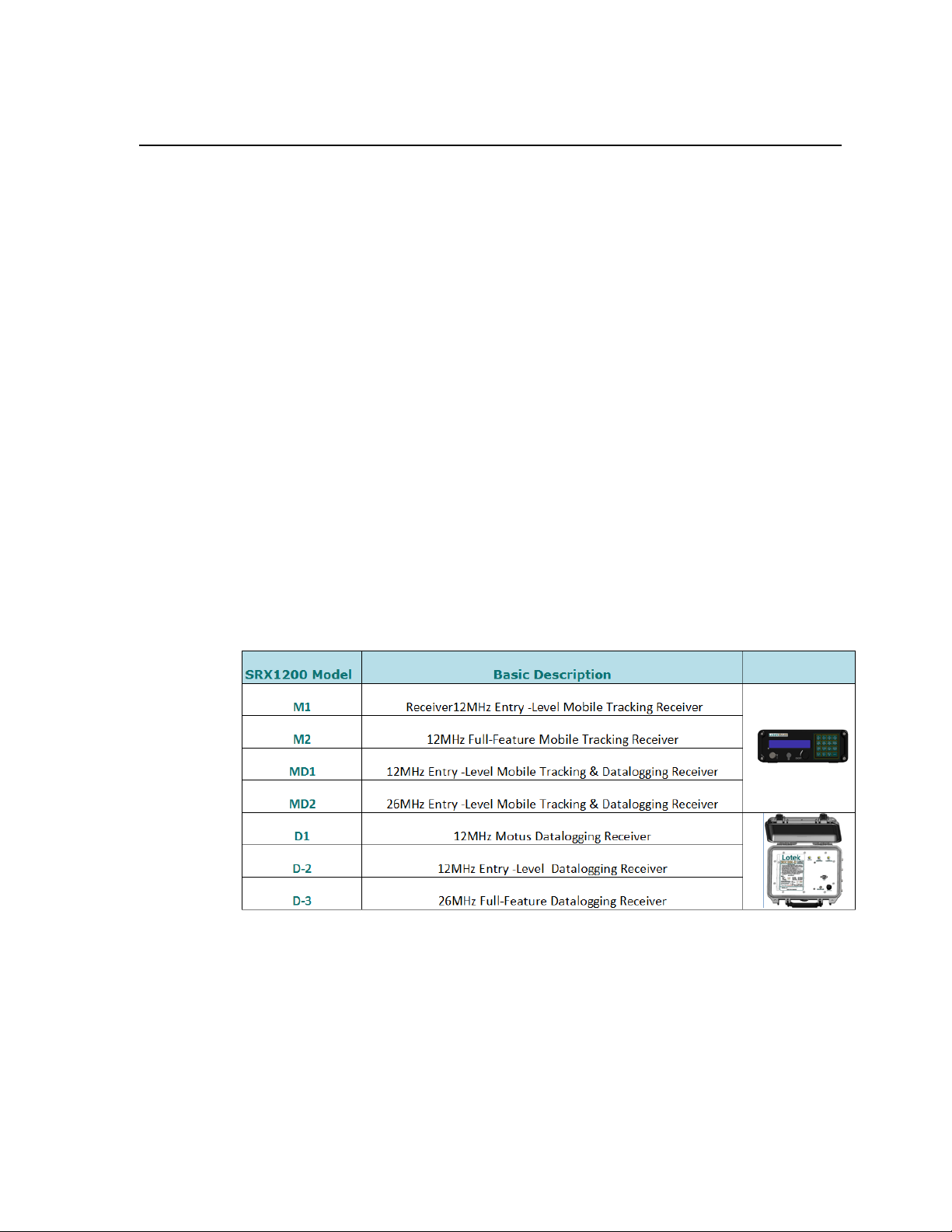
K E Y P A D A N D D I S P L A Y
The keypad and LCD screen define the interface through which user-
configurable parameters are programmed and instructions are issued to the
receiver. Features and functional parameters are nested in a hierarchal design to
simplify navigation through menus and pages. All aspects of the program are
accessed through keys on the keypad.
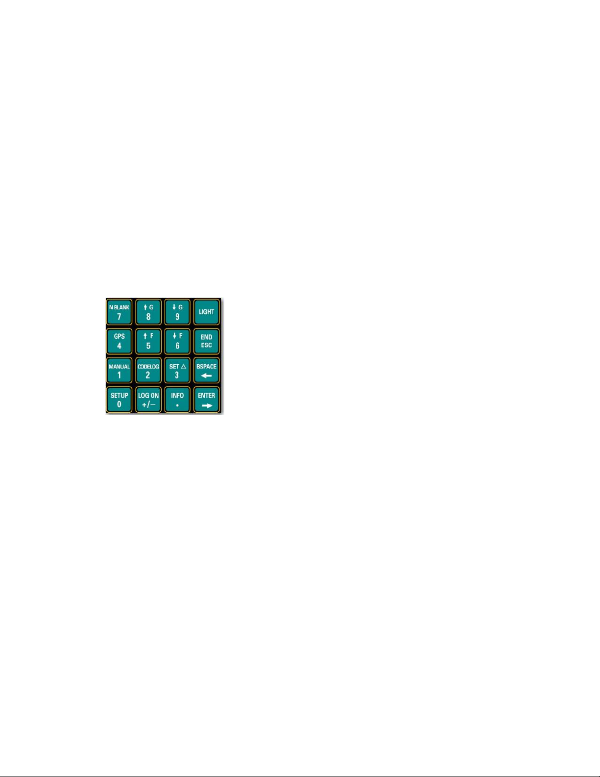
All keys except Light have two functions. Which of the
two functions is active and accessible depends on
previous key selections and the corresponding state of
the receiver relative to the command hierarchy
sequence. Keys labeled Setup,Log On,Info,Manual,
Codelog, and Set Delta provide access to menus and
related sub-menus. The Setup, Manual,and Codelog
keys access modes. Through these modes, specific
aspects of the receiver’s functionality can be enabled, disabled, or amended.
The LCD screen is a two-line display and is used to present and enter data, as
well as to issue command instructions and assist in navigating through available
menus and pages. Each LCD screen presented is referred to as a page. Menus
may often contain several pages to display necessary information and options. To
scroll through pages, use the right and left arrow keys or the END/ESC key.
The LCD display also provides current setting information. The information
displayed depends on whether the receiver is Online or Offline (refer to Logging
on to Receiver section). If the receiver is Online, the LCD shows the current
settings within brackets after the page title and allows new values to be entered.
If the receiver is Offline, the LCD shows the current settings after the title of a
page, but there is no provision for a new value to be entered.

10
K E Y P A D N A V I G A T I O N
KEY FUNCTION
ENTER Once a value is entered, pressing the
Enter key causes the receiver to accept
that entry and save it, provided the
receiver is Online.
END/ESC The END/ESC key is used for menu navigation, for cancelling incomplete
inputs, and for stopping receiver actions in Online mode. During
navigation, this key allows users to return to the previously displayed
menu. For example, after enabling TOA, press the END/ESC key to return
to the Scan Options menu where the TOA feature was first accessed.
The END/ESC key can also be used to cancel an input prior to entry (for
example while entering a frequency 148.100). Many inputs are accepted
automatically, as soon as an appropriate number of characters are entered.
If number is only partially entered and a correction is to be made, pressing
the END/ESC key cancels the operation.
When the receiver is Online, the END/ESC key can also be used to stop the
current operational state, e.g. GPS position acquisition, Scan Cycle, of the
receiver. This action depends on the receiver’s operational mode. When
the receiver is Offline, this END/ESC function does not apply.
NUMBER Keys with a number (0through 9) designation are used in two ways: to
KEYS select menu items and to enter in numeric values.
All selectable menu items have a number designation, e.g. 1) Gain. To select
a menu item, press the corresponding number on the keypad. In this
example, press 1to access the Gain menu. When prompted for a numeric
input, use the keypad numbers to enter a value.
DECIMAL The lower portion of this key provides the decimal point needed for many
input values.
+/- SIGN Plus (+) or minus (-) signs are provided at the beginning of some input
prompts (e.g. >+). Minus signs are necessary when entering the GMT
correction into the receiver. To change a sign, press the +/- key once.

11
ARROW The Right and Left Arrow keys are used for navigating forwards and
KEYS backwards between menu pages. If more than one page is available, a “>”
or a “<--” symbol appears in the lower-right corner of the LCD. Multiple
pages are used to accommodate the limitations of a two-line display; any
menu items or inputs that exceed this space must be spread out. For
example, to see all of the menu options from the Search page in Manual
mode, use the right arrow to scroll through the next two pages of menu
options. The only time an arrow prompt in the lower right corner is not
provided is when the receiver’s battery is low. In this case, a small square
icon is provided indicating low battery status.
BSPACE The Backspace key erases the value of an input one number/value at a
time. This is similar to using the backspace/delete key on a computer
keyboard.
INFO When accessing the INFO key menu items, it is not possible log on to the
receiver. The INFO key provides access to:
• Battery voltage [1)Bat]
• Available memory (in Kilobytes) [2)Mem]
• Configuration settings (Scan Time and Code Set) [5)Cfg]
• Service information (receiver Serial Number and number of hours in operation
since last servicing) [6)Service]
• The factory password (123456) [7)Factory Password]
• Ability to answer an incoming call via the Modem [8)Answer Incoming Call] This
feature is provided for testing and troubleshooting purposes. When a modem is being
used to access the receiver, it rings when a call is made. The receiver is programmed to
automatically answer all calls made. If the receiver does not answer after the modem
rings four or more times, verify that the auto-answer feature is enabled.
The call can still be answered via Info > 8)Answer Incoming Call.
LIGHT Press the Light key to switch the LCD backlight on or off. Use of the
backlit display consumes more power, but is useful in low-light
conditions.
NBLANK Press the key to enable and disable noise blanking. Noise blanking
suppresses audio response of the receiver to eliminate white noise until a
signal is received. When a signal is detected audio performance is
enhanced. This feature can prevent fatigue when using the receiver for
extended periods of time in aircraft or other noisy environments.
GAIN ADJUSTMENT

12
The SRX1200 Gain value range is 0-99 and is applied to
increase/decrease receiver sensitivity. Gain value is adjusted/selected
using the Up or Down Arrows. The amount of gain increment or
decrement can be specified as described on Page 13.
The appropriate gain setting depends on prevailing local ambient noise
conditions at the intended study set. Increasing gain and sensitivity
better enables signal detection at reception limits of the system, but will
also amplify noise events. For autonomous data logging applications in
particular, gain setting adjustment represents an important
consideration during the calibration process, to optimize data collection
efficiency of your telemetry system. Use of the AGC (Adaptive Gain
Control refer to page 24) feature can also be helpful in compensating for
anticipated fluctuations in local ambient noise.
The power of the received signal is reflected in the SRX1200 as an RSSI
(Relative Signal Strength Indicator) value. For practical purposes, RSSI
values will range from low values, e.g, 10, for very weak signals to high
values, e.g. 210, for very strong signals. The RSSI value remains more or
less constant throughout this range, irrespective of the selected gain
setting, although receiver sensitivity increases or decreases based on the
gain value applied. This linear response assists in localizing presence of
instrumented animals and in calibrating multiple SRX1200 receivers that
may require different gain values.
FREQUENCY ADJUSTMENT
Frequencies is adjusted/selected using the Up or Down Arrows. The
amount of increment or decrement is also selected through SET ∆for
frequency as described on Page 13.
When adjusting the frequency or gain manually during tracking
sessions, the receiver will increase or decrease the frequency (kHz) or
gain value based on the Frequency or Gain Delta increment selected.
Set Frequency increment via: Set Delta > 1)Freq
Set Gain increment via: Set Delta > 2)Gain

13
GPS DATA ACQUISITION
The GPS key enables access to acquire GPS fixes. GPS data can be stored
by the receiver either in Monitor mode (manual process) or in Codelog
mode (refer to applicable section). GPS fix should be verified before the
enabling the GPS feature for a project (refer to Codelog Mode section
Enabling/Disabling GPS Positioning), by initiating a scan through
Codelog Mode. During test verification, ensure the GPS antenna is
connected to the receiver and that the antenna has a clear view of the
sky.
A GPS position is acquired by pressing the GPS key on the keypad (key
number 4). While attempting to acquire a position, the LCD screen
displays the number of satellites as they are found.
Once a valid position is acquired, the following information is provided
on the display: Latitude, Longitude, current date, current GMT time,
number of satellites used, HDOP, and PDOP. The display toggles back
and forth, showing the Latitude and Longitude for four seconds and
satellite, HDOP and PDOP information for two seconds. Either time or
date is also displayed and updated every five seconds.
GPS cannot be used when the receiver is logged off. However, it is
possible to log off from the receiver while the receiver is attempting to
acquire a GPS position. When logging on, the display shows the results
of the GPS position. Note that the CRTO (Continuous Record on Time-
Out) is disabled with use of the GPS feature of the receiver.
Press the END/ESC key to discontinue acquiring collecting GPS fixes.

14
R E C E I V E R O P E R A T I O N
Upon start-up, the following screen display is typically presented. This
screen is displayed when no-one is remotely logged on and the receiver is
in its idle (or SETUP) state.
Logging On
Logging on provides the ability to change the operational state of the
receiver. When a valid ‘log on’password is provided the receiver is
considered Online. If no password is provided (logged off) the receiver is
Offline. The differences between Online and Offline are described below:
Offline: the receiver allows read-only access, which means most inputs are
not allowed (unless a log on password is provided). The only allowed
input is the Reset Password function.
Online: the receiver allows full write access,which means that all
functionality and input capabilities are available.
There are a few options for logging on. This is a good time to talk about
the arrow symbol circled in red, which will appear in the lower right of the
display anytime when there are more menu options than can be displayed
on a single view.
To access these extended displays, press the right arrow button, also
labelled “ENTER”/. The left arrow button labelled “BSPACE” will move
backwards to the previous display. The next display (as in example below)
shows the result of pressing the right arrow key. Note that there is still a
right arrow key displayed, meaning there are additional nested screen
options to display.

15
Log on to the receiver as follows:
Press LOG ON key
1)Log On 2)Log Off
Select/press ‘1’ key and ‘Log On’ using default Factory password “123456”
Wait a few seconds for changes to be accepted, at which point the receiver
will return either to its last active state, e.g. monitor, or the start page.
Logging on via the default password allows you to log on quickly,
provided the factory password (“123456”) is being used. This feature is
convenient if you do not need or want a confidential password. Logging
on can be done at any time during operation of the receiver, except when
using the Info key and its menu items. If the default factory password
represents the active password, users can use a quick key log on method
by sequentially pressing the LOG ON and 4 key.
Logging Off
Logging off can be done at any time during receiver operation. Data
collection can continue while limiting access to settings password. Logging
off means the receiver is Offline.
Log off from the receiver as follows:
Press LOG OFF key
Log On 2)Log Off
Select/press ‘2’ key or 3 key as below
Log On > 3)Temporarily Log Off
Once the receiver accepts the changes, the display returns to the start page
(the first screen shown after the receiver is turned on). Temporarily
logging off creates a restriction, whereby logging on is accessible only
from the receiver keypad and is no longer accessible from the SRX Host
software, except via the Host Keypad Simulator.

16
Changing/Resetting Password
Changing the log on password can only be performed in Setup Mode and
when the receiver is Online. Changing the password requires that the old
password be entered, followed by the new one. The receiver automatically
places a slash [/] between the two passwords as they are entered. The
password must consist of six numbers.
Change the password via:
Setup > 3)Change Password
Resetting the log on password can only be done in Setup Mode and when
the receiver is Offline. This feature is not normally used, except to provide
a recovery mechanism if the current password has been lost or forgotten.
Should this occur, contact Lotek support staff, provide the receiver serial
number and a six-digit number a password will be provided to enable
access to the Reset Password function to log on to the receiver as follows:
Reset the password via:
Setup > 3)Reset Password
MANUAL MODE
Manual mode refers to those receiver states in which the user must fully
specify and dynamically modify receiver parameters, e.g, frequency, gain,
in real time, and optimize operation based on local ambient conditions to
improve detection probability. Any changes to these settings are
performed using the keypad.
During operation in Manual mode, data are not automatically logged by
the receiver.. Detected signals are displayed on the LCD screen and are
audibly discernible from the speaker. Adjust the volume as required using
the OFF/VOL knob.
After pressing the Manual key on the keypad, four menu items are
presented:

17
1) Code Set This selection is used if the user intends to track and or log
transmissions from digitally encoded Lotek transmitters. The user selects
from a list of code sets that have been installed in the receiver. Three Code
Set options are presented. Select 1) Code Set and use the keypad to select
or change the active code set. Ensure that the Code Set you have selected
corresponds with the code set programmed for your tags.
2) Search and 3) Signal menu items provide alternate methods of scanning
and changing settings that affect operation in manual mode. The Settings
listed below are common to either ‘Search’or ‘Signal’selection:
• Start a scan- launches the search through the sequence of specified frequencies
based on gain, frequency and step values entered.
• Define the type of transmitter to scan (Beeper/ID/Sensor)
• Define/Change the Set Delta frequency and/or gain
• Acquire a GPS position
• Enter a gain value
• Set the noise threshold
In search mode, the user may specify a start and end frequency, a step size and a
step delay and the receiver will sweep through that range of frequencies,
stopping at each step for the specified amount of time.
Settings unique to ‘Search’include:
• Pause/ Resume a scan
• Enter a minimum frequency
• Enter a maximum frequency
• Define frequency step
• Set the scan time
Settings unique to ‘Signal’include:
• Change antenna port assignment for the master radio antenna
• Change the radio frequency
4) Quick Rec Delay
This feature enables users to define a delay period during which the
receiver will record detected transmitted tag signals. The Quick Record
Delay window is entered as a 2-digit value in seconds. Selecting a 2-digit

18
window, e.g, 30s, requires that a ‘0’ first be entered. The default value is
30s.
CODELOG & MONITOR MODE
The key labeled “CODELOG”, or numeric key “2”, accesses the features of
the receiver that deal with data collection and the receiver configurations
that determine how data is collected OR monitored. This is encompassed
in a receiver mode referred to as CONFIGURED SCANNING, in which
the receiver will operate based upon a preset user-configured scanning
routine.
SRX1200 receivers configured exclusively for Mobile tracking operation
(M-1 and M-2 models) will access MONITOR mode functions when the
CODELOG key is pressed. Receivers configured for both Mobile tracking
and datalogging, e.g., MD-2, MD-3, MD-4, operation have access to
additional features nested under CODELOG mode as further described in
this section.
Both ‘CODELOG’ and MONITOR mode represent an operational state in
which the receiver will auto-scan based on preconfigured parameters
defined by the user. The primary distinction between the two modes is
that scanning under ‘CODELOG’ mode enables continuous and
autonomous data collection during auto-scanning operation (applicable to
MD and D receiver models). Additional features more applicable to long
term autonomous system deployment, e.g., multi-antennas, data
compression and signal processing options, are likewise available.
An extensive list of features are accessible through the Codelog function
key, which allows entry and navigation through a hierarchy of nested and
configurable options based on the receiver model purchased and
corresponding feature suite specific to that model. The hierarchy of user
configurable parameters with applicable by receiver model is presented on
page 18. Detailed descriptions of these parameters follow.

19
CODELOG/MONITOR CONFIGURABLE CHART CONFIGURABLE
PARAMETER CHART
M1 M2 MD1 MD2 SRX-D1 D-2 D-3
Keypad and Display • • • •
Mobile tracking • • • •
Padded Carry Case • • •
PelicanTM Case Housing • • •
Bandwidth 12MHz 12MHz 12MHz 26MHz 1MHz 12MHz 26MHz
Sensor support1• • • •
Autonomous Datalogging • • • • •
Internal battery power • • • •
Antennas 1 1 1-8 1-8 1-4 1-4 1-4
Coded Frequencies (Chan) 5 128 5128 1 5 128
Beeper frequencies (Chan) 20 128 20 128 N/A 20 128
Memory Size 64MB 128MB 32MB 64MB 128MB
Max. Event Record Capacity 16 32M 8M 16 32M
GPS Clock & Position • • • • • •
Code ID & Channel Filter • • • • •
Monitor Mode • •
CRTO function • • • • •
AGC function • • • • •
TOA function • • • • •
ON/OFF Scheduler •
Remote Terminal Control • • •
Multi-codeset scanning • • • •
Remote Notification • •
Feature
SRX1200 Model
Other manuals for SRX1200 Series
2
This manual suits for next models
2
Table of contents
Other Lotek Receiver manuals