LOVATO ELECTRIC VT1 Series User manual

LOVATO ELECTRIC S.P.A.
24020 GORLE (BERGAMO) ITALIA
VIA DON E. MAZZA, 12
TEL. 035 4282111
E-mail: [email protected]
Web: www.LovatoElectric.com
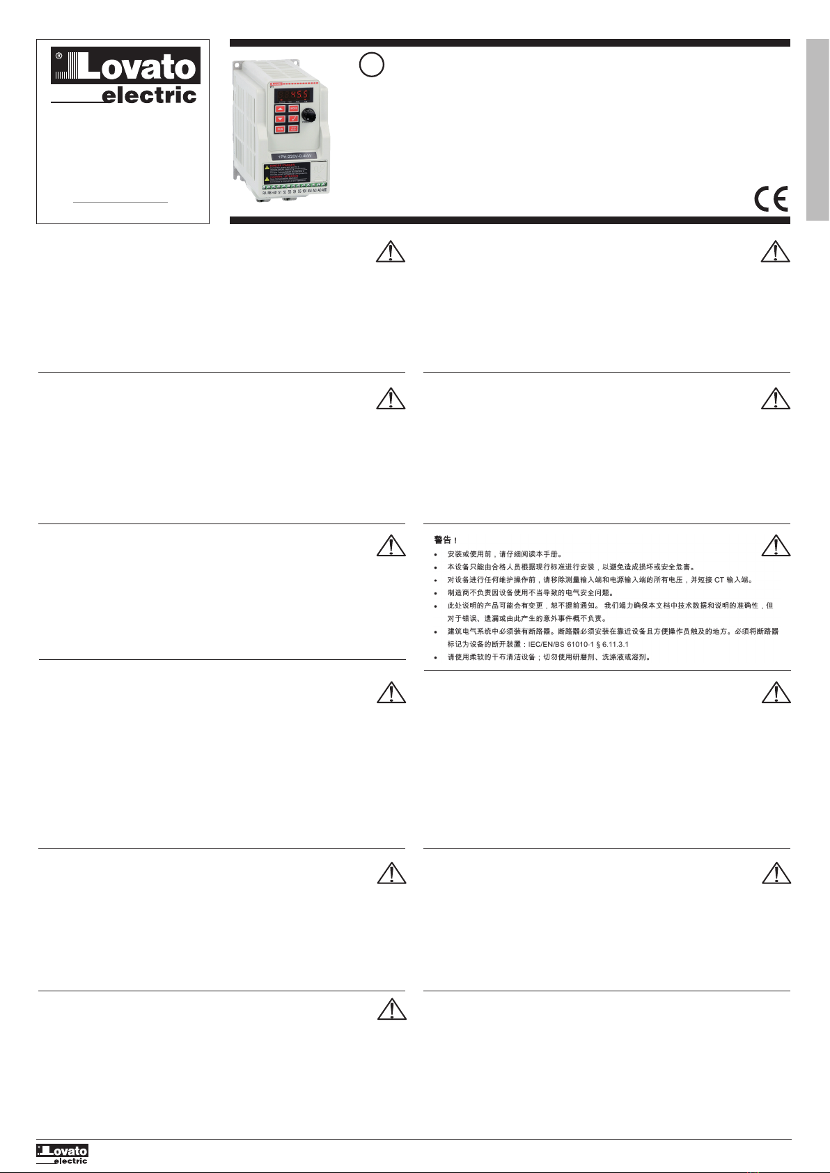
QUICK GUIDE FOR THE CONFIGURATION OF
VARIABLE SPEED DRIVES
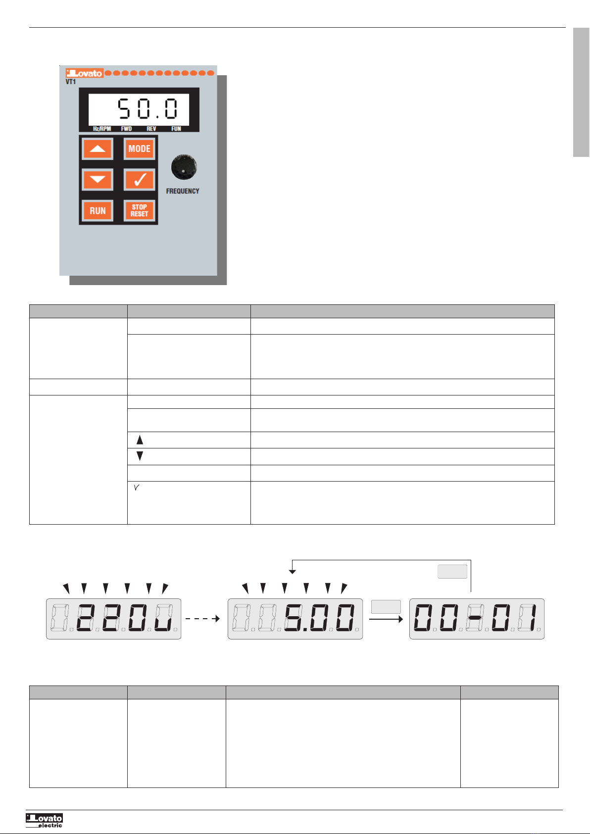
VT1...
GB
G
B
WARNING!
– Carefully read the manual before the installation or use.
– This equipment is to be installed by qualified personnel, complying to current standards, to avoid
damages or safety hazards.
– Before any maintenance operation on the device, remove all the voltages from measuring and supply inpu
and short-circuit the CT input terminals.
– The manufacturer cannot be held responsible for electrical safety in case of improper use of the equipment.
– Products illustrated herein are subject to alteration and changes without prior notice. Technical data and
descriptions in the documentation are accurate, to the best of our knowledge, but no liabilities for errors,
omissions or contingencies arising there from are accepted.
– A circuit breaker must be included in the electrical installation of the building. It must be installed close by
the equipment and within easy reach of the operator. It must be marked as the disconnecting device of the
equipment: IEC /EN/BS 61010-1 § 6.11.3.1.
– Clean the device with a soft dry cloth; do not use abrasives, liquid detergents or solvents.
ATTENTION !
– Lire attentivement le manuel avant toute utilisation et installation.
– Ces appareils doivent être installés par un personnel qualifié, conformément aux normes en vigueur
en matière d’installations, afin d’éviter de causer des dommages à des personnes ou choses.
– Avant toute intervention sur l’instrument, mettre les entrées de mesure et d’alimentation hors tension et
court-circuiter les transformateurs de courant.
– Le constructeur n’assume aucune responsabilité quant à la sécurité électrique en cas d’utilisation impropre
du dispositif.
– Les produits décrits dans ce document sont susceptibles d’évoluer ou de subir des modifications à n’importe
quel moment. Les descriptions et caractéristiques techniques du catalogue ne peuvent donc avoir aucune
valeur contractuelle.
– Un interrupteur ou disjoncteur doit être inclus dans l’installation électrique du bâtiment. Celui-ci doit se
trouver tout près de l’appareil et l’opérateur doit pouvoir y accéder facilement. Il doit être marqué comme le
dispositif d’interruption de l’appareil : IEC/ EN/BS 61010-1 § 6.11.3.1.
– Nettoyer l’appareil avec un chiffon doux, ne pas utiliser de produits abrasifs, détergents liquides ou solvants.
ACHTUNG!
– Dieses Handbuch vor Gebrauch und Installation aufmerksam lesen.
±=XU9HUPHLGXQJYRQ3HUVRQHQXQG6DFKVFKlGHQGUIHQGLHVH*HUlWHQXUYRQTXDOL¿]LHUWHP
Fachpersonal und unter Befolgung der einschlägigen Vorschriften installiert werden.
±9RUMHGHP(LQJULIIDP,QVWUXPHQWGLH6SDQQXQJV]XIXKU]XGHQ0HVVHLQJlQJHQWUHQQHQXQGGLH6WURPZDQGOHU
NXU]VFKOLHȕHQ
±%HL]ZHFNZLGULJHP*HEUDXFKGHU9RUULFKWXQJEHUQLPPWGHU+HUVWHOOHUNHLQH+DIWXQJIUGLHHOHNWULVFKH6LFKHUKHLW
±'LHLQGLHVHU%URVFKUHEHVFKULHEHQHQ3URGXNWHN|QQHQMHGHU]HLWZHLWHUHQWZLFNHOWXQGJHlQGHUWZHUGHQ'LHLP
Katalog enthaltenen Beschreibungen und Daten sind daher unverbindlich und ohne Gewähr.
±,QGLHHOHNWULVFKH$QODJHGHV*HElXGHVLVWHLQ$XVVFKDOWHURGHU7UHQQVFKDOWHUHLQ]XEDXHQ'LHVHUPXVVVLFKLQ
XQPLWWHOEDUHU1lKHGHV*HUlWVEH¿QGHQXQGYRP%HGLHQHUOHLFKW]XJlQJOLFKVHLQ(UPXVVDOV7UHQQYRUULFKWXQJIU
GDV*HUlWJHNHQQ]HLFKQHWVHLQ,(&(1/BS 61010-1 § 6.11.3.1.
– Das Gerät mit einem weichen Tuch reinigen, keine Scheuermittel, Flüssigreiniger oder Lösungsmittel verwenden.
ADVERTENCIA
-Leer atentamente el manual antes de instalar y utilizar el regulador.
-Este dispositivo debe ser instalado por personal cualificado conforme a la normativa de instalación
vigente a fin de evitar daños personales o materiales.
-Antes de realizar cualquier operación en el dispositivo, desconectar la corriente de las entradas de aliment
ción y medida, y cortocircuitar los transformadores de corriente.
-El fabricante no se responsabilizará de la seguridad eléctrica en caso de que el dispositivo no se utilice de
forma adecuada.
-Los productos descritos en este documento se pueden actualizar o modificar en cualquier momento. Por
consiguiente, las descripciones y los datos técnicos aquí contenidos no tienen valor contractual.
-La instalación eléctrica del edificio debe disponer de un interruptor o disyuntor. Éste debe encontrarse cerca
del dispositivo, en un lugar al que el usuario pueda acceder con facilidad. Además, debe llevar el mismo
marcado que el interruptor del dispositivo (IEC/ EN /BS 61010-1 § 6.11.3.1).
-Limpiar el dispositivo con un trapo suave; no utilizar productos abrasivos, detergentes líquidos ni disolventes
ni disolventes.
832=251ċ1Ë
±1iYRGVHSR]RUQČSURþWČWHQHå]DþQHWHUHJXOiWRULQVWDORYDWDSRXåtYDW
±7DWR]DĜt]HQtVPtLQVWDORYDWNYDOL¿NRYDQtSUDFRYQtFLYVRXODGXVSODWQêPLSĜHGSLV\DQRUPDPLSURSĜHGFKi]
Qt~UD]ĤRVREþLSRãNR]HQtYČFt
±3ĜHGMDNêPNROL]iVDKHPGRSĜtVWURMHRGSRMWHPČĜLFtDQDSiMHFtYVWXS\RGQDSČWtD]NUDWXMWHWUDQVIRUPiWRU\SURXGX
±9êUREFHQHQHVHRGSRYČGQRVW]DHOHNWULFNRXEH]SHþQRVWYSĜtSDGČQHYKRGQpKRSRXåtYiQtUHJXOiWRUX
±9êUREN\SRSVDQpYWRPWRGRNXPHQWXPRKRXNG\NROLSURMtW~SUDYDPLþLGDOãtPYêYRMHP3RSLV\D~GDMHXYHGHQpY
NDWDORJXQHPDMtSURWRåiGQRXVPOXYQtKRGQRWX
±6StQDþþLRGSRMRYDþMHQXWQR]DEXGRYDWGRHOHNWULFNpKRUR]YRGXYEXGRYČ0XVHMtEêWQDLQVWDORYDQpYWČVQpEOt]NRVWL
SĜtVWURMHDVQDGQRGRVWXSQpSUDFRYQtNXREVOXK\-HQXWQRKRR]QDþLWMDNRY\StQDFt]DĜt]HQtSĜtVWURMH,(&(1/BS
61010-1
§ 6.11.3.1.
±3ĜtVWURMþLVWČWHPČNNRXXWČUNRXQHSRXåtYHMWHDEUD]LYQtSURGXNW\WHNXWiþLVWLGODþLUR]SRXãWČGOD
AVERTIZARE!
±&LWLĠLFXDWHQĠLHPDQXDOXOvQDLQWHGHLQVWDODUHVDXXWLOL]DUH
±$FHVWHFKLSDPHQWYD¿LQVWDODWGHSHUVRQDOFDOL¿FDWvQFRQIRUPLWDWHFXVWDQGDUGHOHDFWXDOHSHQWUXDHYLWD
GHWHULRUăULVDXSHULFROHOH
±ÌQDLQWHGHHIHFWXDUHDRULFăUHLRSHUDĠLXQLGHvQWUHĠLQHUHDVXSUDGLVSR]LWLYXOXLvQGHSăUWDĠLWRDWHWHQVLXQLOHGHODLQWUăULOH
GHPăVXUDUHúLGHDOLPHQWDUHúLVFXUWFLUFXLWDĠLERUQHOHGHLQWUDUH&7
±3URGXFăWRUXOQXSRDWH¿FRQVLGHUDWUHVSRQVDELOSHQWUXVLJXUDQĠDHOHFWULFăvQFD]GHXWLOL]DUHLQFRUHFWăDHFKLSDPHQ
tului.
±3URGXVHOHLOXVWUDWHvQSUH]HQWXOVXQWVXSXVHPRGL¿FăULORUúLVFKLPEăULORUIăUăQRWL¿FDUHDQWHULRDUă'DWHOHWHKQLFHúL
GHVFULHULOHGLQGRFXPHQWDĠLHVXQWSUHFLVHvQPăVXUDFXQRúWLQĠHORUQRDVWUHGDUQXVHDFFHSWăQLFLRUăVSXQGHUHSHQWUX
HURULOHRPLWHULOHVDXHYHQLPHQWHOHQHSUHYă]XWHFDUHDSDUFDXUPDUHDDFHVWRUD
±7UHEXLHLQFOXVXQGLVMXQFWRUvQLQVWDODĠLDHOHFWULFăDFOăGLULL$FHVWDWUHEXLHLQVWDODWDSURDSHGHHFKLSDPHQWúLvQWUR
]RQăXúRUDFFHVLELOăRSHUDWRUXOXL$FHVWDWUHEXLHPDUFDWFD¿LQGGLVSR]LWLYXOGHGHFRQHFWDUHDOHFKLSDPHQWXOXL
,(&(1/BS 61010-1 § 6.11.3.1.
±&XUăĠDĠLLQVWUXPHQWXOFXXQPDWHULDOWH[WLOPRDOHúLXVFDWQXXWLOL]DĠLVXEVWDQĠHDEUD]LYHGHWHUJHQĠLOLFKL]LVDXVROYHQĠL
ATTENZIONE!
– Leggere attentamente il manuale prima dell’utilizzo e l’installazione.
– Questi apparecchi devono essere installati da personale qualificato, nel rispetto delle vigenti
normative impiantistiche, allo scopo di evitare danni a persone o cose.
– Prima di qualsiasi intervento sullo strumento, togliere tensione dagli ingressi di misura e di alimentazione e
cortocircuitare i trasformatori di corrente.
– Il costruttore non si assume responsabilità in merito alla sicurezza elettrica in caso di utilizzo improprio del
dispositivo.
– I prodotti descritti in questo documento sono suscettibili in qualsiasi momento di evoluzioni o di modifiche.
Le descrizioni ed i dati a catalogo non possono pertanto avere alcun valore contrattuale.
– Un interruttore o disgiuntore va compreso nell’impianto elettrico dell’edificio. Esso deve trovarsi in stretta
vicinanza dell’apparecchio ed essere facilmente raggiungibile da parte dell’operatore. Deve essere marchiato
come il dispositivo di interruzione dell’apparecchio: IEC/EN/BS 61010-1 § 6.11.3.1.
– Pulire l’apparecchio con panno morbido, non usare prodotti abrasivi, detergenti liquidi o solventi.
UWAGA!
±3U]HGXĪ\FLHPLLQVWDODFMąXU]ąG]HQLDQDOHĪ\XZDĪQLHSU]HF]\WDüQLQLHMV]ąLQVWUXNFMĊ
±:FHOXXQLNQLĊFLDREUDĪHĔRVyEOXEXV]NRG]HQLDPLHQLDWHJRW\SXXU]ąG]HQLDPXV]ąE\üLQVWDORZDQHSU]H]
Z\NZDOL¿NRZDQ\SHUVRQHO]JRGQLH]RERZLą]XMąF\PLSU]HSLVDPL
±3U]HGUR]SRF]ĊFLHPMDNLFKNROZLHNSUDFQDXU]ąG]HQLXQDOHĪ\RGáąF]\üQDSLĊFLHRGZHMĞüSRPLDURZ\FKL]DVLODQLDRUD]
]HZU]Hü]DFLVNLSU]HNáDGQLNDSUąGRZHJR
±3URGXFHQWQLHSU]\MPXMHQDVLHELHRGSRZLHG]LDOQRĞFL]DEH]SLHF]HĔVWZRHOHNWU\F]QHZSU]\SDGNXQLHZáDĞFLZHJR
XĪ\WNRZDQLDXU]ąG]HQLD
±3URGXNW\RSLVDQHZQLQLHMV]\PGRNXPHQFLHPRJąE\üZNDĪGHMFKZLOLXGRVNRQDORQHOXE]PRG\¿NRZDQH2SLV\RUD]
GDQHNDWDORJRZHQLHPRJąPLHüZ]ZLą]NX]W\PĪDGQHMZDUWRĞFLXPRZQHM
±:LQVWDODFMLHOHNWU\F]QHMEXG\QNXQDOHĪ\XZ]JOĊGQLüSU]HáąF]QLNOXEZ\áąF]QLNDXWRPDW\F]Q\3RZLQLHQRQ]QDMGRZDü
VLĊZEOLVNLPVąVLHG]WZLHXU]ąG]HQLDLE\üáDWZRRVLąJDOQ\SU]H]RSHUDWRUD0XVLE\üR]QDF]RQ\MDNRXU]ąG]HQLH
VáXĪąFHGRZ\áąF]DQLDXU]ąG]HQLD,(&(1/BS 61010-1 § 6.11.3.1.
±8U]ąG]HQLHQDOHĪ\F]\ĞFLüPLĊNNąV]PDWNąQLHVWRVRZDüĞURGNRZĞFLHUQ\FKSá\QQ\FKGHWHUJHQWRZOXEUR]SXV]F]D
nikow.
ɉɊȿȾɍɉɊȿɀȾȿɇɂȿ
±ɉɪɟɠɞɟɱɟɦɩɪɢɫɬɭɩɚɬɶɤɦɨɧɬɚɠɭɢɥɢɷɤɫɩɥɭɚɬɚɰɢɢɭɫɬɪɨɣɫɬɜɚɜɧɢɦɚɬɟɥɶɧɨɨɡɧɚɤɨɦɶɬɟɫɶɫ
ɨɞɟɪɠɚɧɢɟɦɧɚɫɬɨɹɳɟɝɨɪɭɤɨɜɨɞɫɬɜɚ
±ȼɨɢɡɛɟɠɚɧɢɟɬɪɚɜɦɢɥɢɦɚɬɟɪɢɚɥɶɧɨɝɨɭɳɟɪɛɚɦɨɧɬɚɠɞɨɥɠɟɧɫɭɳɟɫɬɜɥɹɬɶɫɹɬɨɥɶɤɨɤɜɚɥɢɮɢɰɢɪɨɜɚɧɧɵɦ
ɩɟɪɫɨɧɚɥɨɦɜɫɨɨɬɜɟɬɫɬɜɢɢɫɞɟɣɫɬɜɭɸɳɢɦɢɧɨɪɦɚɬɢɜɚɦɢ
±ɉɟɪɟɞɩɪɨɜɟɞɟɧɢɟɦɥɸɛɵɯɪɚɛɨɬɩɨɬɟɯɧɢɱɟɫɤɨɦɭɨɛɫɥɭɠɢɜɚɧɢɸɭɫɬɪɨɣɫɬɜɚɧɟɨɛɯɨɞɢɦɨɨɛɟɫɬɨɱɢɬɶɜɫɟ
ɢɡɦɟɪɢɬɟɥɶɧɵɟɢɩɢɬɚɸɳɢɟɜɯɨɞɧɵɟɤɨɧɬɚɤɬɵɚɬɚɤɠɟɡɚɦɤɧɭɬɶɧɚɤɨɪɨɬɤɨɜɯɨɞɧɵɟɤɨɧɬɚɤɬɵɬɪɚɧɫɮɨɪɦɚɬɨɪɚ
ɬɨɤɚɌɌ
±ɉɪɨɢɡɜɨɞɢɬɟɥɶɧɟɧɟɫɟɬɨɬɜɟɬɫɬɜɟɧɧɨɫɬɶɡɚɨɛɟɫɩɟɱɟɧɢɟɷɥɟɤɬɪɨɛɟɡɨɩɚɫɧɨɫɬɢɜɫɥɭɱɚɟɧɟɧɚɞɥɟɠɚɳɟɝɨ
ɢɫɩɨɥɶɡɨɜɚɧɢɹɭɫɬɪɨɣɫɬɜɚ
±ɂɡɞɟɥɢɹɨɩɢɫɚɧɧɵɟɜɧɚɫɬɨɹɳɟɦɞɨɤɭɦɟɧɬɟɜɥɸɛɨɣɦɨɦɟɧɬɦɨɝɭɬɩɨɞɜɟɪɝɧɭɬɶɫɹɢɡɦɟɧɟɧɢɹɦɢɥɢ
ɭɫɨɜɟɪɲɟɧɫɬɜɨɜɚɧɢɹɦɉɨɷɬɨɦɭɤɚɬɚɥɨɠɧɵɟɞɚɧɧɵɟɢɨɩɢɫɚɧɢɹɧɟɦɨɝɭɬɪɚɫɫɦɚɬɪɢɜɚɬɶɫɹɤɚɤɞɟɣɫɬɜɢɬɟɥɶɧɵɟ
ɫɬɨɱɤɢɡɪɟɧɢɹɤɨɧɬɪɚɤɬɨɜ
±ɗɥɟɤɬɪɢɱɟɫɤɚɹɫɟɬɶɡɞɚɧɢɹɞɨɥɠɧɚɛɵɬɶɨɫɧɚɳɟɧɚɚɜɬɨɦɚɬɢɱɟɫɤɢɦɜɵɤɥɸɱɚɬɟɥɟɦɤɨɬɨɪɵɣɞɨɥɠɟɧɛɵɬɶ
ɪɚɫɩɨɥɨɠɟɧɜɛɥɢɡɢɨɛɨɪɭɞɨɜɚɧɢɹɜɩɪɟɞɟɥɚɯɞɨɫɬɭɩɚɨɩɟɪɚɬɨɪɚȺɜɬɨɦɚɬɢɱɟɫɤɢɣɜɵɤɥɸɱɚɬɟɥɶɞɨɥɠɟɧɛɵɬɶ
ɩɪɨɦɚɪɤɢɪɨɜɚɧɤɚɤɨɬɤɥɸɱɚɸɳɟɟɭɫɬɪɨɣɫɬɜɨɨɛɨɪɭɞɨɜɚɧɢɹ,(&(1/BS 61010-1 § 6.11.3.1.
±Ɉɱɢɫɬɤɭɭɫɬɪɨɣɫɬɜɚɩɪɨɢɡɜɨɞɢɬɶɫɩɨɦɨɳɶɸɦɹɝɤɨɣɫɭɯɨɣɬɤɚɧɢɛɟɡɩɪɢɦɟɧɟɧɢɹɚɛɪɚɡɢɜɧɵɯɦɚɬɟɪɢɚɥɨɜ
ɠɢɞɤɢɯɦɨɸɳɢɯɫɪɟɞɫɬɜɢɥɢɪɚɫɬɜɨɪɢɬɟɥɟɣ
'ø..$7
±0RQWDMYHNXOODQÕPGDQ|QFHEXHONLWDEÕQÕGLNNDWOLFHRNX\XQX]
±%XDSDUDWODUNLúLOHUHYH\DQHVQHOHUH]DUDUYHUPHLKWLPDOLQHNDUúÕ\UUONWHRODQVLVWHPNXUPDQRUPODUÕQD
J|UHNDOL¿\HSHUVRQHOWDUDIÕQGDQPRQWHHGLOPHOLGLUOHU
±$SDUDWDFLKD]KHUKDQJLELUPGDKDOHGHEXOXQPDGDQ|QFH|OoPJLULúOHULQGHNLJHULOLPLNHVLSDNÕPWUDQVIRUPDW|UOHUL
HGHNÕVDGHYUH\DSWÕUÕQÕ]
±hUHWLFLDSDUDWÕQKDWDOÕNXOODQÕPÕQGDQND\QDNODQDQHOHNWULNVHOJYHQOL÷HDLWVRUXPOXOXNNDEXOHWPH]
±%XGRNPDQGDWDULIHGLOHQUQOHUKHUDQHYULPOHUHYH\DGH÷LúLPOHUHDoÕNWÕU%XVHEHSOHNDWDORJGDNLWDULIYHGH÷HUOHU
KHUKDQJLELUED÷OD\ÕFÕGH÷HULKDL]GH÷LOGLU
±%LQDQÕQHOHNWULNVLVWHPLQGHELUDQDKWDUYH\DúDOWHUEXOXQPDOÕGÕU%XDQDKWDUYH\DúDOWHURSHUDW|UQNROD\OÕNODXODúD
LOHFH÷L\DNÕQELU\HUGHROPDOÕGÕU$SDUDWÕFLKD]GHYUHGHQoÕNDUWPDJ|UHYL\DSDQEXDQDKWDUYH\DúDOWHULQPDUNDVÕ
,(&(1/BS 61010-1 § 6.11.3.1.
±$SDUDWÕFLKD]VÕYÕGHWHUMDQYH\DVROYHQWNXOODQDUDN\XPXúDNELUEH]LOHVLOLQL]DúÕQGÕUÕFÕWHPL]OLNUQOHULNXOODQPD\ÕQÕ]
1
31100502I666 GB 06 21

2
G
B
31100502I666 GB 06 21
STEPS TO FOLLOW FOR THE CONFIGURATION OF THE VARIABLE SPEED DRIVE:
See chapter 3 See chapter 4 See chapter 5 See chapter 6See chapter 2See chapter 1
LEARN HOW TO
NAVIGATE THE
MENU
RESET
PARAMETERS TO
DEFAULT
HOW DO YOU
WANT TO COM-
MAND THE RUN
AND STOP OF
THE MOTOR?
HOW DO YOU
WANT TO
ADJUST THE
FREQUENCY OF
THE MOTOR?
SET THE MOTOR
PARAMETERS
CONFIGURE
ADDITIONAL
FUNCTIONS
INDEX
1 NAVIGATION IN THE MENU .................................................................................................................................................. 3
1.1 Operator panel functions ...................................................................................................................................................................... 3
1.2 Digital display description ..................................................................................................................................................................... 3
1.3 Modifying parameters ......................................................................................................................................................................... 5
1.4 Status leds description ......................................................................................................................................................................... 5
2 RESET PARAMETERS TO DEFAULT SETTINGS ........................................................................................................................................ 5
3 COMMAND THE RUN AND STOP OF THE MOTOR .................................................................................................................................... 6
3.1 External terminal block, 2-wire mode, run forward / stop input + run reverse / stop input ...................................................................... 6
3.2 External terminal block, 2-wire mode, run/stop input + forward/reverse direction input ........................................................................ 6
3.3 External terminal block, 3-wire mode .................................................................................................................................................... 6
3.4 External terminal block, 2-wire self-holding run/stop............................................................................................................................. 7
3.5 From the frontal keypad ........................................................................................................................................................................ 7
3.6 From RS485 communication port ......................................................................................................................................................... 8
4 FREQUENCY ADJUSTMENT ..................................................................................................................................................................... 8
4.1 From the frontal keypad ........................................................................................................................................................................ 8
4.2 From the potentiometer integrated on front........................................................................................................................................... 9
4.3 From external potentiometer................................................................................................................................................................. 9
4.4 From voltage analog input signal type 0-10VDC .................................................................................................................................. 10
4.5 From current analog input signal type 0/4-20mA ................................................................................................................................ 10
4.6 Withpresetspeedselections....................................................................................................................................................................11
4.7 From external up/down digital inputs .................................................................................................................................................. 12
4.8 PID control – setpoint adjusted with keypad and feedback signal type 0-10VDC ..................................................................................12
4.9 PID control – setpoint adjusted with keypad and feedback signal type 0/4…20mA ..............................................................................13
4.10 From RS485 communication port ..................................................................................................................................................... 14
5 MOTOR PARAMETERS ........................................................................................................................................................................... 15
6 ADDITIONAL FUNCTIONS ...................................................................................................................................................................... 16
6.1 PID control: functions sleep and wake up ........................................................................................................................................... 16
6.2 Configuration of the function of the relay output ................................................................................................................................. 16
6.3 Configuration of the function of the analog output AO ......................................................................................................................... 17
7 COMMON ERROR CODES ...................................................................................................................................................................... 18

31100502I666 GB 06 21
G
B
3
TYPE ITEM FUNCTION
Digital display and LEDs Main views Frequency, parameters, voltage, current, temperature, fault messages.
LED Status – Hz/RPM: ON when the frequency or line speed is displayed. OFF when the parameters are displayed.
– FWD: ON while the drive is running forward. Flashes while stopped.
– REV: ON while the drive is running reverse. Flashes while stopped.
– FUN: ON when the parameters are displayed. OFF when the measures are displayed.
Potentiometer FREQUENCY Used to set the frequency
Keys on keypad RUN RUN: run at the set frequency.
STOP/RESET
(dual function)
- STOP: Decelerate or coast to stop.
- RESET: Use to reset alarms or resettable faults.
Increment parameter number and preset values.
Decrement parameter number and preset values.
MODE Switch between available displays
(Dual function: a short press for left
shift function, a long press for ENTER
function)
– Left Shift: used while changing the parameters or parameter values
– ENTER: used to display the preset value of parameters and for saving the changed parameter values.
PARAMETER DESCRIPTION RANGE DEFAULT
12-00 Extended display mode 00000 ~77777.
Each digit can be set to 0 to 7
0: Default display (frequency and parameters)
1: Output current
2: Output voltage
3: DC Bus voltage
4: Heat sink temperature
5: PID feedback
6: AVI analog signal input
7: ACI analog signal input
00321
1 NAVIGATION IN THE MENU
1.1 OPERATOR PANEL FUNCTIONS
1.2 DIGITAL DISPLAY DESCRIPTION
On power up digital display screens will be as shown below.
The measures available on the display can be selected with the parameter 12-00. For information about how to modify the parameters refer to chapter 1.3.
POWER SUPPLY FREQUENCY
2 sec. later
PARAMETER
MODE
MODE

4
G
B
31100502I666 GB 06 21
DISPLAY DESCRIPTION
In stop mode shows the set frequency
In run mode shows the actual output frequency
Selected parameter
Parameter value
Output voltage [VAC]
Output current [A]
DC Bus voltage [VDC]
Temperature [°C]
PID feedback value
Error Code
Analog signal value of AVI voltage input or ACI current input. Range ( 0~1000)
MODE
MODE MODE
MODE MODE
MODE MODE
For example, by setting 12-00 = 12345 is enabled the display format shown below.
LED display examples
Temperature
<4>
DC Bus Voltage
<3>
Feedback PID
<5>
Output Current
<1>
2SEC. LATER
POWER SUPPLY
SET FREQUENCY
PARAMETER
Output Volage
<2>

31100502I666 GB 06 21
G
B
5
DESCRIPTION LED status
Frequency / speed indicator Hz/RPM On while displaying frequency or line speed
Menu mode indicator Fun On while displaying parameters
Forward run indicator (FWD)
FWD
On while running forward
FWD
Flashing while stopped in Forward mode
Reverse run indicator (REV)
REV
On while running reverse
REV
Flashing while stopped in Reverse mode
1.3 MODIFYING PARAMETERS
1.4 STATUS LEDS DESCRIPTION
To reset the drive parameters to the factory settings set the parameter 13-08 to one of the following values according to the system rated voltage and frequency (typical value: 1250).
1150: initialization (50Hz,220V/380V)
1160: initialization (60Hz,220V/380V)
1250: initialization (50Hz,230V/400V)
1260: initialization (60Hz,230V/460V)
1350: initialization (50Hz,220V/415V)
1360: initialization (60Hz,230V/400V)
To modify the parameters, use the following keys of the frontal keypad:
• MODE: it allows to switch from the measures view to the parameter view
• : with a quick pressing it is incremented or decremented the selected digit by one (parameter index or value). With an extended pressing it is incremented or
decremented the selected digit continuously
• </ENT : a quick pressing allows to move between the digits of the selected parameter or to access to the parameter to see its value. With an extended pressing it is saved the
value of the modified parameter.
Frequency
short press
MODE
once
short press
</ENT
once
short press
</ENT
twice
long press once
</ENT
long press once
</ENT
short press
once
short press
once
2 RESET PARAMETERS TO DEFAULT SETTINGS

6
G
B
31100502I666 GB 06 21
PARAMETER FUNCTION SETTING DESCRIPTION
00-02 Main run command source selection 1 External run/stop control (terminal block)
00-04 Operation modes for external terminals 0 Forward/stop - Reverse/stop
03-00 Multifunction input S1 0 Forward/stop command
(OFF = stop, ON = run forward)
03-01 Multifunction input S2 1 Reverse/stop command
(OFF = stop, ON = run reverse)
PARAMETER FUNCTION SETTING DESCRIPTION
00-02 Main run command source selection 1 External run/stop control (terminal block)
00-04 Operation modes for external terminals 1 Run/stop - Reverse/forward
03-00 Multifunction input S1 0 Run/stop command
(OFF = stop, ON = run)
03-01 Multifunction input S2 1 Reverse/forward direction command
(OFF = forward, ON = reverse)
PARAMETER FUNCTION SETTING DESCRIPTION
00-02 Main run command source selection 1 External run/stop control (terminal block)
00-04 Operation modes for external terminals 2 3-wire control mode
RA RB +24V S1
S1
S2
S2
S3 S4 S5 10V AVI ACI AO GND
RA RB +24V S1
S1
S2
S2
S3 S4 S5 10V AVI ACI AO GND
RA RB +24V S1
S1
S2
S3
S2 S3 S4 S5 10V AVI ACI AO GND
3 COMMAND THE RUN AND STOP OF THE MOTOR
3.1 EXTERNAL TERMINAL BLOCK, 2-WIRE MODE, RUN FORWARD / STOP INPUT + RUN REVERSE / STOP INPUT
3.2 EXTERNAL TERMINAL BLOCK, 2-WIRE MODE, RUN/STOP INPUT + FORWARD/REVERSE DIRECTION INPUT
3.3 EXTERNAL TERMINAL BLOCK, 3-WIRE MODE
Note. In this mode the terminals S1, S2 and S3 are dedicated to this function according to the diagram above and the preset selections for parameters 03-00, 03-01 and 03-02 have no effect.
S1 = RUN FORWARD / STOP
S2 = RUN REVERSE / STOP
S1 = RUN / STOP
S2 = FORWARD / REVERSE
S1 = RUN (TYPE NO)
S2 = STOP (TYPE NC)
S3 = FORWARD / REVERSE

31100502I666 GB 06 21
G
B
7
PARAMETER FUNCTION SETTING DESCRIPTION
00-02 Main run command source selection 1 External run/stop control (terminal block)
00-04 Operation modes for external terminals 3 2-wire self-holding run/stop
PARAMETER FUNCTION SETTING DESCRIPTION
00-02 Main run command source selection 0 Keypad
RA RB +24V S1 S2 S3
S3
S2S1
S4 S5 10V AVI ACI AO GND
STOP
RESET
RUN = RUN MOTOR
= STOP MOTOR
3.4 EXTERNAL TERMINAL BLOCK, 2-WIRE SELF-HOLDING RUN/STOP
3.5 FROM THE FRONTAL KEYPAD
Timing chart
ON
ON
ON TIME
S1 = FWD command
S2 = REV command
S3 = STOP command
Motor speed
TIME
TIME
TIME
STOP STOPFWD FWDREV
OFF
OFF OFF
Note. In this mode the terminals S1, S2 and S3 are dedicated to this function according to the diagram above and the preset selections for parameters 03-00, 03-01 and 03-02 have no effect.
S1 = RUN FORWARD
S2 = RUN REVERSE
S3 = STOP

8
G
B
31100502I666 GB 06 21
PARAMETER FUNCTION SETTNG DESCRIPTION
00-02 Main run command source selection 2 Communication (RS485)
09-00 Assigned communication station number (serial node) 1 Set the serial node 1…32
09-01 Communication protocol 0 Modbus RTU
09-02 Baudrate 2 Set the communication speed:
0=4800bps, 1=9600bps, 2=19200bps, 3=38400bps
09-03 Stop bit selection 0 Set the number of stop bit:
0=1 stop bit, 1=2 stop bit
09-04 Parity selection 0 Set the parity:
0=none, 1=even parity, 2=odd parity
09-05 Data format selection 0 Set the data format:
0=8bit, 1=7bit
PARAMETER FUNCTION SETTING DESCRIPTION
00-05 Main frequency source selection 0 Keypad
00-12 Frequency upper limit 50 Hz Insert the maximum frequency limit
00-13 Frequency lower limit 0 Hz Insert the minimum frequency limit
00-14 Acceleration time 10 sec Insert the acceleration time
00-15 Deceleration time 10 sec Insert the deceleration time
3.6 FROM RS485 COMMUNICATION PORT
RJ45 connector pinout
For information about Modbus or BACnet messages refer to the instruction I646-VT1 communication manual, downloadable from the website www.LovatoElectric.com
1: Data+
2: Data-
3: Data+
4: Reserved
5: Reserved
6: Data-
7: 5V
8: GND
4 FREQUENCY ADJUSTMENT
4.1 FROM THE FRONTAL KEYPAD
INCREASE THE FREQUENCY
DECREASE THE FREQUENCY

31100502I666 GB 06 21
G
B
9
PARAMETER FUNCTION SETTING DESCRIPTION
00-05 Main frequency source selection 1 Potentiometer on keypad
00-12 Frequency upper limit 50 Hz Insert the maximum frequency limit
00-13 Frequency lower limit 0 Hz Insert the minimum frequency limit
00-14 Acceleration time 10 sec Insert the acceleration time
00-15 Deceleration time 10 sec Insert the deceleration time
PARAMETER FUNCTION SETTING DESCRIPTION
00-05 Main frequency source selection 2 AVI analog signal input
00-12 Frequency upper limit 50 Hz Insert the maximum frequency limit
00-13 Frequency lower limit 0 Hz Insert the minimum frequency limit
00-14 Acceleration time 10 sec Insert the acceleration time
00-15 Deceleration time 10 sec Insert the deceleration time
04-00 AVI/ACI analog input signal type select 0 AVI = signal type 0-10V
RA RB +24V S1 S2 S3 S4 S5 10V AVI ACI AO GND
4.2 FROM THE POTENTIOMETER INTEGRATED ON FRONT
4.3 FROM EXTERNAL POTENTIOMETER

10
G
B
31100502I666 GB 06 21
PARAMETER FUNCTION SETTING DESCRIPTION
00-05 Main frequency source selection 2 AVI analog signal input
00-12 Frequency upper limit 50 Hz Insert the maximum frequency limit
00-13 Frequency lower limit 0 Hz Insert the minimum frequency limit
00-14 Acceleration time 10 sec Insert the acceleration time
00-15 Deceleration time 10 sec Insert the deceleration time
04-00 AVI/ACI analog input signal type select 0 AVI = signal type 0-10V
PARAMETER FUNCTION SETTING DESCRIPTION
00-05 Main frequency source selection 3 Regolazione da segnale analogico in corrente ACI
00-12 Frequency upper limit 50 Hz Insert the maximum frequency limit
00-13 Frequency lower limit 0 Hz Insert the minimum frequency limit
00-14 Acceleration time 10 sec Insert the acceleration time
00-15 Deceleration time 10 sec Insert the deceleration time
04-00 AVI/ACI analog input signal type select 0 or 1 0 = ACI signal type 0…20mA
1 = ACI signal type 4…20mA
RA RB +24V S1 S2 S3 S4 S5 10V AVI ACI AO
0 ...10 VDC
GND
+ -
RA RB +24V S1 S2 S3 S4 S5 10V AVI
0/4...20mA
+ -
ACI AO GND
RA RB +24V S1 S2 S3 S4 S5 10V AVI ACI AO GND
+ -
4.4 FROM VOLTAGE ANALOG INPUT SIGNAL TYPE 0-10VDC
4.5 FROM CURRENT ANALOG INPUT SIGNAL TYPE 0/4-20mA
2 WIRE SENSOR WITH OUTPUT 0/4-20mA, SUPPLIED 24VDC FROM THE DRIVE
Note. If necessary, it is possible to customize the characteristic of the AVI analog input by adjusting the gain (04-02), bias (04-03) and slope (04-05). For more
details refer to the VT1 complete manual I625 (downloadable from the website www.LovatoElectric.com), page 42-43.
Note. If necessary, it is possible to customize the characteristic of the ACI analog input by adjusting the gain (04-07), bias (04-08) and slope (04-10). For more
details refer to the VT1 complete manual I625 (downloadable from the website www.LovatoElectric.com), page 42-43
Note. Alternatively to the supply voltage 24VDC (terminal +24V) it is possible to supply the sensor with voltage 10VDC (terminal 10V).

31100502I666 GB 06 21
G
B
11
PARAMETER FUNCTION SETTING DESCRIPTION
00-05 Main frequency source selection 0...6
Set the frequency source to use when all the preset speed
inputs are OFF
(0=keypad, 1=potentiometer on front, 2=AVI input, 3= ACI
input, etc…)
00-12 Frequency upper limit 50 Hz Insert the maximum frequency limit
00-13 Frequency lower limit 0 Hz Insert the minimum frequency limit
00-14 Acceleration time 10 sec Insert the acceleration time
00-15 Deceleration time 10 sec Insert the deceleration time
00-02 Main run command source selection 1 External run/stop control (terminal block)
00-04 Operation modes for external terminals 0 Forward/stop - Reverse/stop
03-00 Multifunction input S1 0 Forward/stop command
(OFF = stop, ON = run forward)
03-01 Multifunction input S2 2 Preset speed 1 (05-02)
03-02 Multifunction input S3 3 Preset speed 2 (05-03)
03-03 Multifunction input S4 4 Preset speed 4 (05-05)
05-02 Preset speed 1 ...Hz Insert preset speed 1
05-03 Preset speed 2 ...Hz Insert preset speed 2
05-04 Preset speed 3 ...Hz Insert preset speed 3
05-05 Preset speed 4 ...Hz Insert preset speed 4
05-06 Preset speed 5 ...Hz Insert preset speed 5
05-07 Preset speed 6 ...Hz Insert preset speed 6
05-08 Preset speed 7 ...Hz Insert preset speed 7
S4 S3 S2 ACTIVATED PRESET SPEED
OFF OFF OFF Preset speed 0 (frequency adjusted according to setting of 00-05)
OFF OFF ON Preset speed 1 (05-02)
OFF ON OFF Preset speed 2 (05-03)
OFF ON ON Preset speed 3 (05-04)
ON OFF OFF Preset speed 4 (05-05)
ON OFF ON Preset speed 5 (05-06)
ON ON OFF Preset speed 6 (05-07)
ON ON ON Preset speed 7 (05-08)
RA RB +24V S1
S1
S2
S2
S3
S3
S4
S4
S5 10V AVI ACI AO GND
4.6 WITH PRESET SPEED SELECTIONS
S1 = RUN / STOP
S2 = PRESET SPEED 1
S3 = PRESET SPEED 2
S4 = PRESET SPEED 4
Selection table of preset speeds

12
G
B
31100502I666 GB 06 21
PARAMETER FUNCTION SETTING DESCRIPTION
00-05 Main frequency source selection 4 External up/down frequency control
00-12 Frequency upper limit 50 Hz Insert the maximum frequency limit
00-13 Frequency lower limit 0 Hz Insert the minimum frequency limit
00-14 Acceleration time 10 sec Insert the acceleration time
00-15 Deceleration time 10 sec Insert the deceleration time
00-02 Main run command source selection 1 External run/stop control (terminal block)
00-04 Operation modes for external terminals 0 Forward/stop - Reverse/stop
03-00 Multifunction input S1 0 Forward/stop command
(OFF = stop, ON = run forward)
03-01 Multifunction input S2 8 Up command (increase frequency)
03-02 Multifunction input S3 9 Down command (decrease frequency)
PARAMETER FUNCTION SETTING DESCRIPTION
00-05 Main frequency source selection 6 PID output frequency
00-12 Frequency upper limit 50 Hz Insert the maximum frequency limit
00-13 Frequency lower limit 0 Hz Insert the minimum frequency limit
00-14 Acceleration time 5 sec Insert the acceleration time
00-15 Deceleration time 5 sec Insert the deceleration time
04-00 AVI/ACI analog input signal type select 0 AVI = signal type 0-10V
10-00 PID target value selection 4 PID setpoint set from keypad, parameter 10-02
10-01 PID feedback value selection 1 PID feedback = AVI analog signal input
10-02 PID target (keypad input) ...% Set the value of PID setpoint (*)
10-03 PID mode selection 1 PID enabled
10-21 Max PID feedback 100 Insert the value of the PID feedback corresponding to the maximum value of the AVI input (10V).
The unit of measure is defined by 12-02.
10-22 Min PID feedback 0 Insert the value of the PID feedback corresponding to the minimum value of the AVI input (0V).
The unit of measure is defined by 12-02.
12-00 Extended display mode 01256 On the display are showing these measures: frequency, current, voltage, PID feedback, AVI signal
input
12-01 PID feedback display format 1 0=integer, 1=1 decimal place, 2=2 decimal places
12-02 PID feedback display unit setting 1 Display of PID feedback in pressure (pb)
RA RB +24V S1
S1
S2
S2
S3
S3
S4 S5 10V AVI ACI AO GND
RA RB +24V S1 S2 S3 S4 S5 10V AVI ACI AO
0 ...10 VDC
GND
+ -
4.7 FROM EXTERNAL UP/DOWN DIGITAL INPUTS
4.8 PID CONTROL – SETPOINT ADJUSTED WITH KEYPAD AND FEEDBACK SIGNAL TYPE 0-10VDC
(*) Setting of the target PID setpoint
Example. Suppose to have a transducer with output 0-10V corresponding to a pressure 0-10Bar. To set a target of 3.5Bar, set 10-02=35% (which means 35% of the range 0-10V = 3.5Bar).
Note.
• If necessary, it is possible to adjust the PID control constants with the parameters 10-05 (proportional gain), 10-06 (integral time) and 10-07 (derivative time).
• It is also possible to enable the function sleep and wake up, which allows to decelerate the motor until it stops at the reaching of the PID setpoint value, with consequent energy saving.
For more information see the chapter 6.1 PID control: functions sleep and wake up.
S1 = RUN / STOP
S2 = INCREASE FREQUENCY (UP)
S3 = DECREASE FREQUENCY (DOWN)

31100502I666 GB 06 21
G
B
13
PARAMETER FUNCTION SETTING DESCRIPTION
00-05 Main frequency source selection 6 PID output frequency
00-12 Frequency upper limit 50 Hz Insert the maximum frequency limit
00-13 Frequency lower limit 0 Hz Insert the minimum frequency limit
00-14 Acceleration time 5 sec Insert the acceleration time
00-15 Deceleration time 5 sec Insert the deceleration time
04-00 AVI/ACI analog input signal type select 0 or 1 0 = ACI signal type 0…20mA
1 = ACI signal type 4…20mA
10-00 PID target value selection 4 PID setpoint set from keypad, parameter 10-02
10-01 PID feedback value selection 2 PID feedback = ACI analog signal input
10-02 PID target (keypad input) ...% Set the value of PID setpoint (*)
10-03 PID mode selection 1 PID enabled
10-21 Max PID feedback 100 Insert the value of the PID feedback corresponding to the maximum value of the ACI input (20mA).
The unit of measure is defined by 12-02
10-22 Min PID feedback 0 Insert the value of the PID feedback corresponding to the minimum value of the ACI input (0/4mA).
The unit of measure is defined by 12-02.
12-00 Extended display mode 01257 On the display are showing these measures: frequency, current, voltage, PID feedback, ACI signal
input
12-01 PID feedback display format 1 0=integer, 1=1 decimal place, 2=2 decimal places
12-02 PID feedback display unit setting 1 Display of PID feedback in pressure (pb)
RA RB +24V S1 S2 S3 S4 S5 10V AVI
0/4...20mA
+ -
ACI AO GND
RA RB +24V S1 S2 S3 S4 S5 10V AVI ACI AO GND
+ -
(*) Setting of the target PID setpoint
Example. Suppose to have a transducer with output 4-20mA corresponding to a pressure 0-10Bar. To set a target of 3.0Bar, set 10-02=30% (which means 30% of the range
4-20mA = 3.0Bar).
Note.
• If necessary, it is possible to adjust the PID control constants with the parameters 10-05 (proportional gain), 10-06 (integral time) and 10-07 (derivative time).
• It is also possible to enable the function sleep and wake up, which allows to decelerate the motor until it stops at the reaching of the PID setpoint value, with consequent energy
saving. For more information see the chapter 6.1 PID control: functions sleep and wake up.
4.9 PID CONTROL – SETPOINT ADJUSTED WITH KEYPAD AND FEEDBACK SIGNAL TYPE 0/4…20mA
2 WIRE SENSOR WITH OUTPUT 0/4-20mA SUPPLIED 24VDC FROM THE DRIVE
Note. Alternatively to the supply voltage 24VDC (terminal +24V) it is possible to supply the sensor with voltage 10VDC (terminal 10V).

14
G
B
31100502I666 GB 06 21
PARAMETER FUNCTION SETTING DESCRIPTION
00-05 Main frequency source selection 5 Communication (RS485)
09-00 Assigned communication station number (serial node) 1 Set the serial node 1…32
09-01 Communication protocol 0 Modbus RTU
09-02 Baudrate 2 Set the communication speed:
0=4800bps, 1=9600bps, 2=19200bps, 3=38400bps
09-03 Stop bit selection 0 Set the number of stop bit:
0=1 stop bit, 1=2 stop bit
09-04 Parity selection 0 Set the parity:
0=none, 1=even parity, 2=odd parity
09-05 Data format selection 0 Set the data format:
0=8bit, 1=7bit
4.10 FROM RS485 COMMUNICATION PORT
RJ45 connector pinout
For information about Modbus or BACnet messages refer to the instruction I646-VT1 communication manual, downloadable from the website www.LovatoElectric.com.
1:Data+
2:Data-
3:Data+
4:Reserved
5:Reserved
6:Data-
7:5V
8:GND

31100502I666 GB 06 21
G
B
15
PARAMETER FUNCTION SETTING DESCRIPTION
00-00 Control mode 0 0 = V/f mode
1 = Sensorless vector mode (SLV)
01-00 V/f characteristic 1
Set one of the following Volts/Hz patterns:
1 (50Hz) or 4 (60Hz) = linear (general use)
2 (50Hz) or 5 (60Hz) = linear with high starting torque
3 (50Hz) or 6 (60Hz)= decreasing torque (pumps, fans)
7 = customizable by the user
02-01 Motor rated current ___A Set the motor rated current (see motor nameplate)
02-03 Motor rated speed ___rpm Set the motor rated speed (see motor nameplate)
02-04 Motor rated voltage ___V Set the motor rated voltage (see motor nameplate)
02-05 Motor rated power ___kW Set the motor rated power (see motor nameplate)
02-06 Motor rated frequency ___Hz Set the motor rated frequency (see motor nameplate)
1
2
3
5 MOTOR PARAMETERS
All the other parameters must be left to default settings.
In case of setting 00-00=0, the V/f characteristics shape can be set with parameter 01-00.
SLV (Sensorless vector) control is used for obtaining best performance from a motor, especially at low speeds or for applications with dynamic speed change.
To enable the sensorless vector control, follow these steps:
• Set 00-00=1.
• Set the motor parameters 02-01 and 02-03~02-06.
• Activate the motor auto tune function by setting 02-07=1. During the auto tune function the display will show AT and show END briefly when it is completed,
then the display return to the frequency display.
For more information about the characteristics of the available patterns refer to the description of the parameter 01-00 on the VT1 complete manual I625,
downloadable from the website www.LovatoElectric.com.
1
2
3

16
G
B
31100502I666 GB 06 21
PARAMETER FUNCTION SETTING DESCRIPTION
10-17 PID sleep frequency level ... Hz Set the frequency threshold for the activation of the sleep function
10-18 PID sleep function delay time 10 sec Set the delay time for the activation of the sleep function
10-19 PID wake up frequency level ... Hz Set the frequency threshold for the deactivation of the sleep function
(wake up)
10-20 PID wake up function delay time 5 sec Set the delay time for the deactivation of the sleep function (wake up)
PARAMETER FUNCTION SETTING DESCRIPTION
03-11 Relay output function (RA-RB)
0 Run: the relay is active as long as the motor is running
1 Fault: the relay is active in presence of alarm
4 The relay is active when the output frequency is greater than the frequency detection level 03-13
5 The relay is active when the output frequency is below the frequency detection level 03-13
10 Motor overload: the relay is active in presence of the alarm OL1 (motor overload protection)
13 Output current reached: the relay is active when the motor current absorption is greater than the threshold
03-15 for a time longer than 03-16.
14
Brake control: in accelerating mode, the relay will be ON as soon as the output frequency reaches the brake
release level 03-17; in deceleration the output will be OFF as soon as the actual output frequency reaches the
brake engage level 03-18.
6 ADDITIONAL FUNCTIONS
6.1 PID CONTROL: FUNCTIONS SLEEP AND WAKE UP
For the PID control it is possible to enable the function of sleep and wake up, which allows to decelerate the motor until it stops at the reaching of the PID setpoint value, with consequent energy
saving. The functioning of the sleep and wake up function is showing in the following chart.
• When the PID output frequency falls below the sleep frequency threshold (10-17) for a time longer than the sleep delay (10-18), the motor is decelerated up to 0Hz and the
drive enter in the sleep mode.
• When the PID output frequency returns above the wake up frequency threshold (10-19) for a time longer than the wake up delay (10-20), the drive exits the sleep mode and
automatically reactivates the motor to follow the setpoint.
delay
delay
time
PID output frequency
Actual output frequency
To configure the function of the relay output (terminals RA-RB) set the parameter 03-11.
The table below shows the most common used functions.
Relay output
250VAC/1A
(30VDC/1A)
Sleep and wake up function operating chart.
6.2 CONFIGURATION OF THE FUNCTION OF THE RELAY OUTPUT
wake up
threshold
sleep delay
wake up delay
sleep
threshold

31100502I666 GB 06 21
G
B
17
PARAMETER FUNCTION SETTING DESCRIPTION
03-19 Relay output status type 0 or 1 0 = normally open contact (NO)
1 = normally closed contact (NC)
PARAMETER FUNCTION SETTING DESCRIPTION
04-11 Analog output (AO) mode
0 Output frequency
1 Frequency setpoint
2 Output voltage
3 DC bus voltage
4 Motor current
04-11 Measured assigned to AO XmaX
0 Output frequency Frequency upper limit 00-12
1 Frequency setpoint Frequency upper limit 00-12
2 Output voltage Motor rated voltage 02-04
3 DC bus voltage 400V
4 Motor current 2 times rated current of the drive
6.3 CONFIGURATION OF THE FUNCTION OF THE ANALOG OUTPUT AO
The contact type of the relay output RA-RB can be configured with the parameter 03-19:
To configure the function of the analog output AO (0-10VDC, 1mA max) set the parameter 04-11.
Analog voltage
output 0~10VDC
If necessary, it is possible to adjust the following characteristics of the analog output AO: gain (04-12), bias (04-13), bias selection (04-14) and slope (04-15). For more
information refer to the VT1 complete manual I625, downloadable from the website www.LovatoElectric.com.

31100502I666 GB 06 21
G
B
18
ERROR CODE DESCRIPTION POSSIBLE CAUSES CORRECTIVE ACTIONS
– OU – Voltage too high when stopped Detection circuit malfunction Consult with the supplier
– LU – Voltage too low when stopped
1. Power voltage too low
2. Pre-charge resistor or fuse burnt out.
3. Detection circuit malfunction
1. Check if the power voltage is correct
2. Failed resistor or fuse. Consult with the supplier
3. Consult with the supplier
– OH – The drive is overheated when stopped
1. Detection circuit malfunction
2. Ambient temperature too high or bad
ventilation
Improve the ventilation conditions. If no results, consult with
the supplier.
OH – C The drive is overheated during running
– IGBT temperature is too high or poor
ventilation
– Temperature sensor error or circuit
malfunctions
– Reduce carrier frequency (11-01)
– Improve the ventilation conditions. If no results, consult
with the supplier.
OC–A Over-current at acceleration
1. Acceleration time too short
2. The capacity of the motor exceeds the
capacity of the drive
3. Short circuit between the motor coil and
the case
4. Short circuit between motor wiring and
ground
5. IGBT module damaged
1. Set a longer acceleration time
2. Replace drive with one that has the same rating as that of the
motor
3. Check the motor
4. Check the wiring
5. Consult with the supplier
OC–C Over-current at fixed speed 1. Transient load change
2. Transient power change
1. Increase the capacity of the drive
2. Install inductor on the power supply input side
OC–d Over-current at deceleration The preset deceleration time is too short Set a longer deceleration time
OC–S Over-current at start
1. Short circuit between the motor coil and
the case
2. Short circuit between motor coil and
ground
3. IGBT module damaged
1. Check the motor
2. Check the wiring
3. Consult with the supplier
OU–C Excessive voltage during operation or
deceleration
1. Deceleration time setting too short or
excessive load inertia
2. Power voltage varies widely (fluctuates)
1. Set a longer deceleration time
2. Check the power supply voltage
PF Input phase loss Abnormal fluctuations in the main circuit
voltage
– Check the main circuit power supply wiring
– Check the power supply voltage
OC Over-current during stop Detection circuit malfunction Consult with the supplier
OL 1 Motor overload Loading too large Increase the motor capacity
OL 2 Drive overload Excessive load Increase the drive capacity
CL Drive over current Drive over current warning: drive current
reached the level of over current protection
Check load condition and running period time.
Wait 1 minute to reset. If it occurs CL or OL2 up to 4 successive
times then wait 5 minutes to reset.
LU-C Voltage too low during operation 1. Power voltage too low
2. Power voltage varies widely (fluctuates)
1. Improve power quality
2. Consider adding a reactor at the power input side
OUSP Motor rotation over speed The actual rotation speed is different to the
set speed
1. Check for excessive load
2. Check weather frequency setting signal is right or not
OH4 Motor over heat error (PTC)
1. If temperature detected increases above
the set limit in 08-13 and for the delay
time set in 08-12 then the display will
show OH4 and the motor will coast to
stop
2. OH4 can be reset when the temperature
detection level is lower than the set level
in 08-14
1. Improve the ventilation conditions
2. Adjust the parameter 08-15
7 COMMON ERROR CODES

31100502I666 GB 06 21
G
B
19
ERROR CODE DESCRIPTION POSSIBLE CAUSES CORRECTIVE ACTIONS
OPErr Operator setting error
The parameter 09-02 is set to 4 but the
remote keypad (VT1X C02) is
disconnected.
1. Use STOP/RESET key of drive to remove the error code
2. Set 09-02 to 0~3
LOC
1. Parameter locked active
2. Motor direction locked
3. Password enabled
1. Attempt to modify frequency parameter
while 13-06>0
2. Attempt to reverse direction when
11-00=1.
3. Password enabled with parameter
13-07, set the correct password will
show LOC
1. Modify 13-06
2. Modify 11-00 (set 0 to enable the reverse run direction)
Err1 Keypad operation error
1. Press or while 00-05/00-06 > 0 or
running at preset speed.
2. Attempt to modify a parameter which
cannot be modified during operation
(refer to the parameter list on
instruction I624 or I625)
1. The keys or are available for modifying parameters only
when 00-05 / 00-06=0
2. Modify the parameter in STOP mode.
Err2 Parameter setting error
1. 00-13 is within the range of
[11-08 ± 11-11] or [11-09 ± 11-11] or
[11-10 ± 11-11]
2. 00-12 d00-13
3. 00-05/00-06 or 10-00/10-01 set the
same value
4. Modifying parameters 01-01~01-09
when 01-00z7
5. If this parameter is parameterized for
both functions (AVI/PTC) at the same
time, PTC function is enabled by
setting 08-10z0
6. Parameter password 13-07 set
incorrect
1. Modify 11-08~11-10 or 11-11.
2. Set 00-12>00-13
3. Set 00-05 and 00-06 to be different
4. Set 01-00=7
5. PTC function source can not be set the same source (AVI)
with frequency command and PID command
6. Please set correct password
Err5 Modification of parameter is not avai-
lable in communication
1. Control command sent during com-
munication
2. Attempt to modify the function 09-
02~09-05 during communication
1. Issue enable command before communication
2. Set parameters 09-02~09-05 function before communication
Err6 Communication failed
1. Wiring error
2. Communication parameter
setting error
3. Communication ground disconnected
4. External noise
1. Check hardware and wiring of communication
2. Check the setting of parameters 09-00~09-05
3. CON2 connector needs to be connected to the earth
4. Increase the setting value of 09-08
Err7 Parameter conflict
1. Attempt to modify the function
13-00/13-08
2. Voltage and current detection
circuit is abnormal
If reset is not possible, please consult with the supplier
StP0 Zero speed at stop In V/f mode, StP0 comes out at less than 1.3Hz (50Hz set) or at less than 1.5Hz (60Hz set).
In SLV mode, StP0 comes out at less than 1Hz.
StP1 Fail to start directly on power up
If the drive is set for external terminal control mode (00-02/00-03=1) and the run input is active at power
up but the direct start function is disabled (07-04=1) the drive cannot be started and will flash StP1. See
description of 07-04 on the instruction I625.
StP2 Keypad stop operated when drive is
configured in external control mode
If the stop key is pressed while the drive is set to external control mode (00-02/00-03=1) then StP2 flashes
after stop.
Release and re-activate the run contact to restart the drive.
For other error messages and information about the corrective actions refer to the chapter 4.TROUBLESHOOTING AND MAINTENANCE of the complete manual I625,
downloadable from the website www.LovatoElectric.com.
Other manuals for VT1 Series
1
Table of contents
Other LOVATO ELECTRIC Media Converter manuals