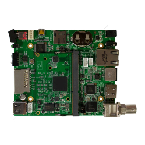
Idis DA-MC1101 User manual

10/100/1000 Base-T
to Gigabit Fiber
Media Converter
DA-MC1101
Operation Manual
Powered by
All manuals and user guides at all-guides.com
all-guides.com

2
Before Using the Product
FCC Compliance Statement
This device complies with part 15 of the FCC Rules.
Operation is subject to the following two conditions:
(1) This device may not cause harmful interference, and
(2) This device must accept any interference received,
including interference that may cause undesired operation.
Note: This equipment has been tested and found to comply with the limits for a Class A
digital device, pursuant to part 15 of the FCC Rules. These limits are designed to provide
reasonable protection against harmful interference when the equipment is operated in a
commercial environment.
This equipment generates, uses and can radiate radio frequency energy and, if not
installed and used in accordance with the instructions, may cause harmful interference to
radio communications. Operation of this equipment in a residential area is likely to cause
harmful interference in which case the user will be required to correct the interference at
his own expense.
User’s Caution Statement
Caution: Any changes or modifications to the equipment not expressly approved by the
party responsible for compliance could void your authority to operate the equipment.
Product Overview
DA-MC1101 is designed to fulfill requirements for forming a Gigabit network, and can
extend a connection up to 10KM using fiber optic cables.
The LED indicators located on the front panel of DA-MC1101 shows the operating status
of the product.
All manuals and user guides at all-guides.com

3
Product Features
●Supports automatic negotiation feature
●Supports automatic MDI/MDI-X detection
●Supports LED status indicators
●Mode switching using DIP switches
Accessories
The product consists of the following components.
Power FDX
Status
Speed
Diag
FO TX
Link / Act
Main Unit (DA-MC1101) 5V DC adapter Operation Manual
Overview
Front
LED indicators
RJ45 port
SFP Slot
Power FDX
Status
Speed
Diag
FO TX
Link / Act
ON
5VDC
1 2 3 4 5 6 7 8
3
1
2
All manuals and user guides at all-guides.com

4
Back
DIP switch
Adapter input
Power FDX
Status
Speed
Diag
FO TX
Link / Act
ON
5VDC
1 2 3 4 5 6 7 8
45
1SFP Slot Insert the SFP module and connect the fiber optic cable.
2LED indicators Shows the status of DA-MC1101. Refer to "Checking LED
Indicators" for more details.
3RJ45 port Use the RJ45 port to connect the UTP cable.
4Adapter input Connect a 5V DC adapter. Connect the adapter first before
turning the device On.
5DIP switch
Settings of DA-MC1101 can be changed using the DIP
switches.
Refer to "DIP Switch Settings" for more details.
Installation
Extending fiber optic cable using two DA-MC1101 units***
1 Connect the Video In port of DirectIP™ NVR and RJ45 port of DA-MC1101 #1
using a UTP cable.
2 Insert an SFP module into SFP slot of DA-MC1101 #1 and connect the fiber optic
cable to the module.
The connection distance can be extended to 500m to 10km using fiber optic cables.
All manuals and user guides at all-guides.com

5
3 Insert an SFP module into SFP slot of DA-MC1101 #2 and connect the fiber optic
cable to the module.
4 Connect the RJ45 port of DA-MC1101 #2 to a DirectIP ™ Switching Hub or a
network camera using a UTP cable.
Installation Layout
Power FDX
Status
Speed
Diag
FO TX
Link / Act
Power FDX
Status
Speed
Diag
FO TX
Link / Act
DirectIP™ NVR
Extending a fiber optic cable using and one DA-MC1101 and
DirectIP™Gigabit PoE Switch***
1 Connect the Video In port of DirectIP™ NVR and RJ45 port of DA-MC1101
using a UTP cable.
2 Insert an SFP module into SFP slot of DA-MC1101 and connect the fiber optic
cable to the module.
Types of Cables
Fiber optic cable
UTP Cable (Data only)
All manuals and user guides at all-guides.com

6
• The connection distance can be extended to 500m to 10km using fiber optic cables.
• The connection distance is determined by the SFP module and the fiber optic cable.
• For more details on supported SFP modules, refer to "7. Supported SFP Modules".
3 Insert an SFP module into SFP slot of DirectIP™Gigabit PoE Switch and
connect the fiber optic cable to the module.
4 Connect the RJ45 port of DirectIP™Gigabit PoE Switchand the network camera
using a UTP cable.
The SFP modules at both ends of the cable and the fiber optic cable must have identical types.
5 Connect the DC 5V adapter and check the status of the LED indicator.
Installation Layout
Power FDX
Status
Speed
Diag
FO TX
Link / Act
DirectIP(tm) NVR
Types of Cables
Fiber optic cable
UTP Cable (Data only)
All manuals and user guides at all-guides.com
all-guides.com

7
Checking Other Information
DIP Switch Settings
In factory settings, Pin 1 and Pin 5 are switched On and the rest are switched Off.
Pin No. Operation Off On
1 TX Auto-Negotiation Disable Enable
2 Manual TX Data Rate 10M/100M 10M 100M
3 Manual TX Data Rate 1000M 10M or 100M 1000M
4 Flow Control Disable Enable
5 Fiber Auto-Negotiation Force Enable
6 Reserved Always Off
7 LLF(Link Loss Forwarding) Disable Enable
8 TX configuration From S/W From DIP
Diag
button
Press the button once to perform a loopback test.
To return to initial settings, press and hold the button for 10 seconds.
Diag button is located in the front panel.
Auto-Negotiation must be disabled to change Data Rate and Duplex Mode settings.
All manuals and user guides at all-guides.com

8
Checking LED Indicators
LED Color Operation
Power Green Turns on when power is connected.
TX Link/Act
Green
Turns on when the connection between remote device and
TX cable is established.
Blinks when transferring data.
Orange Blinks when fiber optic cable connection is disconnected in
LLF Mode.
FO Link/Act
Green
Turns on when the connection between remote device and
fiber optic cable is established.
Blinks when transferring data.
Orange Blinks when fiber optic cable connection is disconnected in
LLF Mode.
FDX Green Turns on in Full Duplex Mode, turns off in Half Duplex Mode.
Speed Green Turns on when TX is operating on 100M network. Turns off
when connected at 10M or disconnected.
Orange Turns on when TX is operating in 1000M network.
Status
Green Turns on when TX and FO are connected.
Blinks during loopback test.
Orange Turns on when connection to TX or FO is disconnected.
Blinks when diagnostics fails.
Supported SFP Modules
The system's SFP ports support the following types of SFP modules:
Standard Diameter
(um)
Wavelength
(nm) Length Mode Connector SFP Module
1000BASE-SX
50/125 850 500m Multi LC Finisar
FTLF8519P3BNL
62.5/125 850 300m Multi LC
1000BASE-LX 9/125 1310 10Km Single LC Finisar
FTLF1318P3BTL
All manuals and user guides at all-guides.com

9
Specifications
Model DA-MC1101
Network Protocols IEEE 802.3, 802.3u, 802.3ab, 802.3z
Port type 1 x RJ-45 LAN connector, 1 x SFP slot
LED type Power, FDX, Status, Speed, FO Link/ACT, TX
Link/ACT
Power adapter I/P AC 100-240V O/P DC 5V, 2A
Power consumption 3.4W
Dimensions (W)X(D)X(H) 71 X 94 X 26 (mm)
Certifications FCC Class A, CE, KC
Environmental
Conditions
Operating
Temperature
0℃ ~ 50℃
Weight 160g
Humidity 5%~90% RH
All manuals and user guides at all-guides.com

All manuals and user guides at all-guides.com

All manuals and user guides at all-guides.com
all-guides.com

IDIS Co., Ltd.
For more information, please visit at
www.idisglobal.com Ver. 1.00
All manuals and user guides at all-guides.com
Other manuals for DA-MC1101
1
Table of contents
Other Idis Media Converter manuals
