LOVATO ELECTRIC CX02 User manual

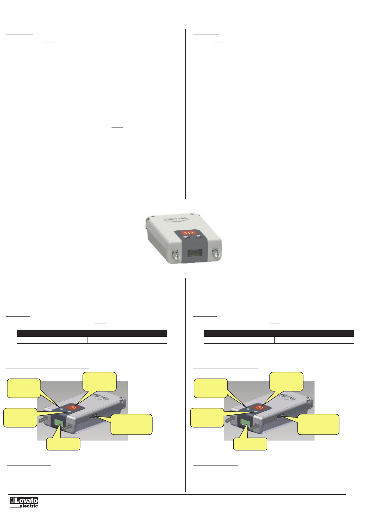
Dispositivo IR – Wi-Fi
MANUALE OPERATIVO
IR – Wi-Fi device
INSTRUCTIONS MANUAL
CX02
Dichiarazione UE: http://www.LovatoElectric.com/CX02/CX02/snp UE declaration: http://www.LovatoElectric.com/CX02/CX02/snp
– Carefully read the manual before the installation or use.
– This equipment is to be installed by qualified personnel, complying to current standards, to avoid damages or safety hazards.
– Before any maintenance operation on the device, remove all the voltages from measuring and supply inputs and short-circuit the CT input terminals.
–The manufacturer cannot be held responsible for electrical safety in case of improper use of the equipment.
– Products illustrated herein are subject to alteration and changes without prior notice. Technical data and descriptions in the documentation are accurate,
to the best of our knowledge, but no liabilities for errors, omissions or contingencies arising there from are accepted.
–A circuit breaker must be included in the electrical installation of the building. It must be installed close by the equipment and within easy reach of the operator. It
must be marked as the disconnecting device of the equipment: IEC/EN/BS 61010-1 § 6.11.3.1.
– Clean the instrument with a soft dry cloth; do not use abrasives, liquid detergents or solvents.
– Leggere attentamente il manuale prima dell’utilizzo e l’installazione.
–Questi apparecchi devono essere installati da personale qualificato, nel rispetto delle vigenti normative impiantistiche, allo scopo di evitare danni a persone o
cose.
– Prima di qualsiasi intervento sullo strumento, togliere tensione dagli ingressi di misura e di alimentazione e cortocircuitare i trasformatori di corrente.
–Il costruttore non si assume responsabilità in merito alla sicurezza elettrica in caso di utilizzo improprio del dispositivo.
–I prodotti descritti in questo documento sono suscettibili in qualsiasi momento di evoluzioni o di modifiche. Le
descrizioni ed i dati
a catalogo non possono pertanto avere alcun valore contrattuale.
– Un interruttore o disgiuntore va compreso nell’impianto elettrico dell’edificio. Esso deve trovarsi in stretta
vicinanza dell’apparecchio ed essere facilmente raggiungibile da parte dell’operatore. Deve essere marchiato come il dispositivo di
interruzione dell’apparecchio: IEC/EN/BS 61010-1 § 6.11.3.1.
– Pulire lo strumento con panno morbido, non usare prodotti abrasivi, detergenti liquidi o solventi.
– Lire attentivement le manuel avant toute utilisation et installation.
– Ces appareils doivent être installés par un personnel qualifié, conformément aux normes en vigueur en matière d'installations, afin d'éviter de causer des
dommages à des personnes ou choses.
–Avant toute intervention sur l'instrument, mettre les entrées de mesure et d'alimentation hors tension et court-circuiter les transformateurs de courant.
– Le constructeur n'assume aucune responsabilité quant à la sécurité électrique en cas d'utilisation impropre du dispositif.
Les produits décrits dans ce document sont susceptibles d'évoluer ou de subir des modifications à n'importe quel moment. Les descriptions et caractéristiques
techniques du catalogue ne peuvent donc avoir aucune valeur contractuelle.
– Un interrupteur ou disjoncteur doit être inclus dans l'installation électrique du bâtiment. Celui-ci doit se trouver tout près de l'appareil et l'opérateur doit pouvoir y
accéder facilement. Il doit être marquee comme le dispositif d'interruption de l'appareil : IEC/EN/BS 61010-1 § 6.11.3.1.
– Nettoyer l’appareil avec un chiffon doux, ne pas utiliser de produits abrasifs, détergents liquides ou solvants.
– Dieses Handbuch vor Gebrauch und Installation aufmerksam lesen.
– Zur Vermeidung von Personen- und Sachschäden dürfen diese Geräte nur von qualifiziertem Fachpersonal und unter Befolgung der einschlägigen Vorschriften
installiert werden.
–Vor jedem Eingriff am Instrument die Spannungszufuhr zu den Messeingängen trennen und die Stromwandler kurzschlie/en.
–Bei zweckwidrigem Gebrauch der Vorrichtung übernimmt der Hersteller keine Haftung für die elektrische Sicherheit.
– Die in dieser Broschüre beschriebenen Produkte können jederzeit weiterentwickelt und geändert werden. Die im Katalog enthaltenen Beschreibungen und Daten
sind daher unverbindlich und ohne Gewähr.
–In die elektrische Anlage des Gebäudes ist ein Ausschalter oder Trennschalter einzubauen. Dieser muss sich in unmittelbarer Nähe des Geräts befinden und vom
Bediener leicht zugänglich sein. Er muss als Trennvorrichtung für das Gerät gekennzeichnet sein: IEC/EN/BS 61010-1 § 6.11.3.1.
–Das Gerät mit einem weichen Tuch reinigen, keine Scheuermittel, Flüssigreiniger oder Lösungsmittel verwenden.
– Leer atentamente el manual antes de instalar y utilizar el regulador.
–Este dispositivo debe ser instalado por personal cualificado conforme a la normativa de instalación vigente a fin de evitar daños personales o materiales.
– Antes de realizar cualquier operación en el dispositivo, desconectar la corriente de las entradas de alimentación y medida, y cortocircuitar los transformadores de
corriente.
–El fabricante no se responsabilizará de la seguridad eléctrica en caso de que el dispositivo no se utilice de forma adecuada.
–Los productos descritos en este documento se pueden actualizar o modificar en cualquier momento. Por consiguiente,
las descripciones y los datos técnicos aquí contenidos no tienen valor contractual.
– La instalación eléctrica del edificio debe disponer de un interruptor o disyuntor. Éste debe encontrarse cerca del dispositivo, en un lugar al que el usuario pueda
acceder con facilidad. Además, debe llevar el mismo marcado que el interruptor del dispositivo (IEC/EN/BS 61010-1 § 6.11.3.1).
– Limpiar el dispositivo con un trapo suave; no utilizar productos abrasivos, detergentes líquidos ni
disolventes.
– Navod se pozorn%pro!t%te, nežza!nete regulator instalovat a použivat.
– Tato za'izeni smi instalovat kvalifikovani pracovnici v souladu s platnymi p'edpisy a normami pro p'edchazeni uraz*osob !i poškozeni v%ci.
–P'ed jakymkoli zasahem do p'istroje odpojte m%'ici a napajeci vstupy od nap%ti a zkratujte transformatory proudu.
– Vyrobce nenese odpov%dnost za elektrickou bezpe!nost v p'ipad%nevhodneho použivani regulatoru.
– Vyrobky popsane v tomto dokumentu mohou kdykoli projit upravami !i dalšim vyvojem. Popisy a udaje uvedene v katalogu nemaji proto žadnou smluvni hodnotu.
– Spina!!i odpojova!je nutno zabudovat do elektrickeho rozvodu v budov%. Museji byt nainstalovane v t%sne blizkosti p'istroje a snadno dostupne pracovniku
obsluhy. Je nutno ho ozna!it jako vypinaci za'izeni p'istroje:
IEC/EN/BS 61010-1 § 6.11.3.1.
–P'istroj !ist%te m%kkou ut%rkou, nepouživejte abrazivni produkty, tekuta !istidla !i rozpoušt%dla.
–Citi)i cu aten)ie manualul inainte de instalare sau utilizare.
– Acest echipament va fi instalat de personal calificat, in conformitate cu standardele actuale, pentru a evita deterior"ri sau pericolele.
– Inainte de efectuarea oric"rei opera)iuni de intre)inere asupra dispozitivului, indep"rta)i toate tensiunile de la intr"rile de m"surare i de alimentare i scurtcircuita)i
bornele de intrare CT.
– Produc"torul nu poate fi considerat responsabil pentru siguran)a electric"in caz de utilizare incorect"a echipamentului.
– Produsele ilustrate in prezentul sunt supuse modific"rilor i schimb"rilor f"r"notificare anterioar". Datele tehnice i
descrierile din documenta)ie sunt precise, in m"sura cunotin)elor noastre, dar nu se accept"nicio r"spundere pentru erorile, omiterile sau evenimentele
neprev"zute care apar ca urmare a acestora.
– Trebuie inclus un disjunctor in instala)ia electric"a cl"dirii. Acesta trebuie instalat aproape de echipament iintr-o zon"uor accesibil"operatorului. Acesta trebuie
marcat ca fiind dispozitivul de deconectare al echipamentului: IEC/EN/BS 61010-1 § 6.11.3.1.
–Cur")a)i instrumentul cu un material textil moale i uscat; nu utiliza)i substan)e abrazive, detergen)i lichizi sau solven)i.
– Przed u+yciem i instalacj#urz#dzenia nale+y uwa+nie przeczyta niniejsz#instrukcj$.
– W celu unikni$cia obra+e&osob lub uszkodzenia mienia tego typu urz#dzenia musz#by instalowane przez wykwalifikowany personel, zgodnie z obowi#zuj#cymi
przepisami.
– Przed rozpocz$ciem jakichkolwiek prac na urz#dzeniu nale+y od#czy napi$cie od wej( pomiarowych I zasilania oraz zewrze zaciski przekadnika pr#dowego.
– Producent nie przyjmuje na siebie odpowiedzialno(ci za bezpiecze&stwo elektryczne w przypadku niewa(ciwego u+ytkowania urz#dzenia.
– Produkty opisane w niniejszym dokumencie mog#by w ka+dej chwili udoskonalone lub zmodyfikowane.
Opisy oraz dane katalogowe nie mog#mie w zwi#zku z tym +adnej warto(ci umownej.
– W instalacji elektrycznej budynku nale+y uwzgl$dni prze#cznik lub wy#cznik automatyczny. Powinien on znajdowa si$w bliskim s#siedztwie urz#dzenia i by
atwo osi#galny przez operatora. Musi by oznaczony jako urz#dzenie su+#ce do wy#czania urz#dzenia: IEC/EN/BS 61010-1 § 6.11.3.1
–Urz#dzenie nale+y czy(ci mi$kk#szmatk#, nie stosowa (rodkow (ciernych, pynnych detergentow lub
rozpuszczalnikow.
–4G<=;< N<C FG?HIJF7IR A CEDI7=J ?B? SAHFBJ7I7M?? JHIGE@HI97, 9D?C7I<BRDE E>D7AECRI<HR H E;<G=7D?<C D7HIEUP<:E GJAE9E;HI97.
–1E ?>8<=7D?< IG79C ?B? C7I<G?7BRDE:E JP<G87 CEDI7= ;EB=<D HJP<HI9BUIRHU IEBRAE A97B?K?M?GE97DDQC F<GHED7BEC 9 HEEI9<IHI9?? H
;<@HI9JTP?C? DEGC7I?97C?.
–4<G<; FGE9<;<D?<C BT8QL G78EI FE I<LD?N<HAECJ E8HBJ=?97D?T JHIGE@HI97 D<E8LE;?CE E8<HIEN?IR 9H< ?>C<G?I<BRDQ< ? F?I7TP?< 9LE;DQ<
AEDI7AIQ, 7 I7A=< >7CADJIR D7AEGEIAE 9LE;DQ< AEDI7AIQ IG7DHKEGC7IEG7 IEA7 (55).
–4GE?>9E;?I<BR D< D<H<I EI9<IHI9<DDEHIR >7 E8<HF<N<D?< SB<AIGE8<>EF7HDEHI? 9 HBJN7< D<D7;B<=7P<:E ?HFEBR>E97D?U JHIGE@HI97.
–2>;<B?U, EF?H7DDQ< 9 D7HIEUP<C ;EAJC<DI<, 9 BT8E@ CEC<DI CE:JI FE;9<G:DJIRHU ?>C<D<D?UC ?B? JHE9<GO<DHI9E97D?UC. 4ESIECJ A7I7BE=DQ<
;7DDQ< ? EF?H7D?U D< CE:JI G7HHC7IG?97IRHU A7A ;<@HI9?I<BRDQ< H IENA? >G<D?U AEDIG7AIE9
–6B<AIG?N<HA7U H<IR >;7D?U ;EB=D7 8QIR EHD7P<D7 79IEC7I?N<HA?C 9QABTN7I<B<C, AEIEGQ@ ;EB=<D 8QIR G7HFEBE=<D 98B?>? E8EGJ;E97D?U 9
FG<;<B7L ;EHIJF7 EF<G7IEG7. 09IEC7I?N<HA?@ 9QABTN7I<BR ;EB=<D 8QIR FGEC7GA?GE97D A7A EIABTN7TP<< JHIGE@HI9E E8EGJ;E97D?U:
IEC/EN/BS 61010-1 § 6.11.3.1.
–3N?HIAJ JHIGE@HI97 FGE?>9E;?IR H FECEPRT CU:AE@ HJLE@ IA7D?, 8<> FG?C<D<D?U 78G7>?9DQL C7I<G?7BE9, =?;A?L CETP?L HG<;HI9 ?B? G7HI9EG?I<B<@.
– Montaj ve kullanımdan once bu el kitabınıdikkatlice okuyunuz.
– Bu aparatlar kiilere veya nesnelere zarar verme ihtimaline karıyururlukte olan sistem kurma normlarına gore kalifiye personel tarafından monte edilmelidirler
–Aparata (cihaz) herhangi bir mudahalede bulunmadan once olcum girilerindeki gerilimi kesip akım transformatorlerinede kısa devre yaptırınız.
–Uretici aparatın hatalıkullanımından kaynaklanan elektriksel guvenlie ait sorumluluk kabul etmez.
– Bu dokumanda tarif edilen urunler her an evrimlere veya deiimlere acıktır. Bu sebeple katalogdaki tarif ve deerler herhangi bir balayıcıdeeri haiz deildir.
– Binanın elektrik sisteminde bir anahtar veya alter bulunmalıdır. Bu anahtar veya alter operatorun kolaylıkla ulaabilecei yakın bir yerde olmalıdır. Aparatı
(cihaz) devreden cıkartma gorevi yapan bu anahtar veya alterin markası: IEC/EN/BS 61010-1 § 6.11.3.1.
–Aparatı(cihaz) sıvıdeterjan veya solvent kullanarak yumuak bir bez ile siliniz aındırıcıtemizlik urunleri kullanmayınız.
I358IGB08_22 31100178

Introduzione
•Il dispositivo CX02 apre agli installatori ed ai manutentori la possibilità di
lavorare in un modo nuovo, libero dagli impedimenti dei cavi e con una
velocità, comodità e sicurezza mai avute prima.
•Esso consente il collegamento fra Tablet, Smartphone o PC verso gli
apparecchi LOVATO Electric dotati di interfaccia IR frontale.
•In tutte le situazioni di lavoro sul campo dove si opera in condizioni difficoltose
(all’aperto o in presenza di ambienti ristretti, rumorosi o scomodi) questo
adattatore permette di ottenere un collegamento veloce, affidabile fino a
grande distanza in modo da operare da postazioni più comode e sicure.
•Il collegamento a raggi infrarossi consente di lavorare in assoluta sicurezza
(isolamento galvanico) su apparecchi IP65 senza la necessità di aprire il
quadro di controllo per ottenere il collegamento con l’apparecchio da
programmare o controllare.
•Oltre a funzionare come convertitore wireless, CX02 è anche dotato di una
memoria interna che consente di memorizzare e scaricare progetti e dati dagli
apparecchi LOVATO Electric, allo stesso modo di una comune chiavetta USB.
Introduction
•The CX02 device open to installers and maintainers the ability to work in a new
way, free from the problems caused by cables and with a very high level of
speed, safety and comfort.
•It enables the connection between a Tablet, Smartphone or PC and any
LOVATO Electric device with front IR interface.
•In all situations of field work where you work in difficult conditions (outdoors or
in the presence of small, noisy or uncomfortable environment) this adapter
allows you to get a fast, reliable link up to a great distance in order to operate
from locations more comfortable and safe.
•The infrared link allows to work in total safety (galvanic insulation) on IP65
devices without the need to open the electrical panel to obtain connection with
the unit to be programmed or serviced.
•In addition to functioning as a wireless converter, CX02 is also equipped with
an internal memory that can store and download data and projects from
LOVATO Electric equipment, in the same way as an ordinary USB stick.
Descrizione
•Connessione verso apparecchi LOVATO Electric tramite interfaccia ottica IR.
•Connessione verso Tablet, Smartphone o PC via Wi-Fi.
•Un tasto per accensione, spegnimento e attivazione menu.
•Due LED per stato collegamento e stato batteria.
•Connettore micro-USB per carica della batteria e per funzionamento come
convertitore USB (non-wireless).
Description
•Connection to LOVATO Electric devices via optical IR port.
•Connection to Tablet, Smartphone or PC via Wi-Fi.
•One button for switching on and off and activate the dongle menu.
•Two LEDs for link status and battery status.
•Micro-USB connector for charging the battery and to operate as a USB
converter (non-wireless).
Compatibilità con i prodotti LOVATO Electric
Il dispositivo CX02 può essere abbinato a tutti i prodotti LOVATO Electric provvisti di
porta ottica IR.
LOVATO Electric products compatibility
CX02 device can be connected to all LOVATO Electric products fitted with a front
optical port.
Indirizzo IP
L’indirizzo e la porta IP di default usati dal CX02 sulla rete Wi-Fi sono riportati nella
seguente tabella:
Queste impostazioni devono essere usate sul PC quando si utilzza il CX02.
Indirizzo IP Porta IP
1.2.3.4 2000
IP Address
The IP address and port used by CX02 on the Wi-Fi network are listed in the
following table:
These settings have to be used on the PC when using CX02.
IP Address IP Port
1.2.3.4 2000
Procedura di connessione del modulo Module connection procedure
Carica della batteria
Prima dell’utilizzo sottoporre l’apparecchio ad una carica completa della batteria,
lasciandolo collegato ad una sorgente di alimentazione USB fino a che il LED
batteria assume il colore verde.
Charging the battery
Before using the device fully charge the battery, leaving it connected to a USB
power source until the battery LED will glow green.
Connessione USB
per comunicazione e
ricarica batteria
Porta ottica IR
Pulsante
accensione/
spegnimento
LED stato di
carica della
batteria
LED di stato
della
comunicazione
USB connector for
communication and
battery recharge
IR Optical port
ON / OFF
pushbutton
LED battery
charge status
LED
link state

Utilizzo non-wireless Non-wireless mode
Quando il CX02 è collegato ad un PC tramite un cavo USB, oltre al caricamento
della batteria si ottiene anche il funzionamento come adattatore USB non-wireless.
In queste condizioni il funzionamento è simile a quello dell’adattatore CX01.
When CX02 is connected to a PC via a USB cable, apart from charging the battery it
is possible to make it operate like a non-wireless USB adapter.
In this conditions, the operation of the dongle is similar to the CX01 adapter.
Accensione
Tenere premuto il pulsante per 2s per attivare il dispositivo CX02.
Spegnimento
Tenere premuto per 3s il pulsante per spegnere definitivamente CX02.
Il dispositivo si spegne automaticamente dopo 30s se non rimane in prossimità di
una porta ottica IR funzionante.
Indicazioni LED
LED IR WIfi Traffico dati
Rosso fisso NO - -
Arancio lamp. OK Connesso, Stand-by -
Arancio fisso OK Connesso, Pronto -
Verde fisso OK Connesso, Attivo No
Verde lamp. OK Connesso, Attivo Si
LED Stato carica batteria
Rosso < 10 %
Arancio >10%, < 90%
Verde > 90%
Power on
Press and hold the button for 2 seconds to activate the CX02 device.
Power off
Press and hold for 3 seconds the button to turn off permanently CX02.
The device automatically turns off after 30 seconds if it is not placed in front to an
active IR port.
LED indications
LED IR WIfi Data traffic
Red steady NO - -
Orange blink OK Connected, Stand-by -
Orange steady OK Connected, Ready -
Green steady OK Connected, Active No
Green blink OK Connected, Active Yes
LED Battery charge status
Red < 10 %
Orange >10%, < 90%
Green > 90%
Menu dongle
Per accedere al menu dongle è necessario eseguire la seguente procedura di
accensione:
•inserire il dispositivo CX02 nell’apposita sede dell’apparecchio con cui si
intende comunicare;
•accendere CX02 premendo il pulsante per 2s;
•attendere che il LED diventi di colore arancio lampeggiante;
•premere per 3 volte consecutivamente e velocemente il tasto del CX02.
Sul display dell’apparecchio base verrà visualizzato il
Menu dongle
rappresentato
nella sezione sottostante:
Menu dongle
Per navigare nel menu dongle usare i tasti freccia sull’apparecchio base, seguendo
le indicazioni della barra sull’ultima riga della pagina.
Selezionare il comando voluto e confermarlo.
Nota: per i comandi da D1 a D4 viene richiesta una seconda conferma per eseguire
l’operazione selezionata.
Descrizione dei comandi:
D1: permette di eseguire lo scaricamento (download) del menu setup
dell’apparecchio. I dati verranno salvati nella memoria non volatile del CX02.
Se durante il trasferimento dei dati avviene un qualsiasi errore (es. chiavetta non
perfettamente collegata all’apparecchio) al termine del download apparirà il
messaggio di errore ‘
CHEKSUM ERROR - RETRY COMMAND’
. In questa
situazione i dati di setup non vengono salvati.
D2: permette di trasferire i dati memorizzati nel CX02 con il comando D1 ad un
nuovo apparecchio.
D3: permette di eseguire il download di tutti i dati dell’apparecchio (setup, logo,
sensori, pagina info, eventi) a cui è collegato il dispositivo CX02. I dati verranno
salvati nella memoria non volatile del dispositivo CX02. Se durante il trasferimento
dei dati avviene un qualsiasi errore (es. chiavetta non perfettamente collegata
all’apparecchio) al termine del download apparirà il messaggio di errore ‘CHEKSUM
ERROR RETRY COMMAND’. In questa situazione i dati non vengono salvati.
D4: permette di trasferire i dati memorizzati nel CX02 con il comando D3 ad un
nuovo apparecchio.
D5: visualizza informazioni sui dati attualmente contenuti nel CX02.
Dongle menu
To enter the dongle menu it is necessary to perform the start-up procedure
described below:
•insert the device CX02 into the IR port of the device with which you want
to communicate
•switch CX02 on by pressing the button for 2s
•wait until the LED becomes orange flashing
•press 3 times consecutively and fast the device button.
The base device display will show the
Dongle menu
represented in the section
below:
Dongle menu
To navigate the dongle menu use the arrow keys on the basic, following the
directions of the bar on the last line of the page.
Select the desired command and confirm it.
Note: for each command from D1 to D4 a second confirmation is requested before
performing the selected operation.
Command description:
D1: allows to download the setup menu from the device to the dongle. The data is
saved in non-volatile memory of the CX02. If during the data transfer any error
occurs (eg dongle not perfectly connected to the device), ten after the download the
display will show error message ‘
CHECKSUM ERROR - RETRY COMMAND
'. In
this situation the setup data is not saved. Retry D1 command.
D2: allows to transfer the data stored in the CX02 (with previous command D1) to a
different device.
D3: allows to download all the data of the device (setup, logo, sensors, page info,
events) and save it in the non-volatile memory of CX02. If during the data transfer
any error occurs (eg dongle not perfectly inserted in the device IR port) then after
the download the display will show error message ‘
CHECKSUM ERROR - RETRY
COMMAND
'. In this situation the setup data is not saved. Retry D3 command.
D4: allows to transfer the data stored in the CX02 with the command D3 to a
different device.
D5: shows information about data currently stored in the internal memory of the
CX02.

Vedere seguente figura:
Dongle Info
•DEVICE ID indica la descrizione dell’apparecchio dal quale è stato
eseguito il download dei dati.
•MODEL – SW. REV – HW. REV - PAR. REV indicano il modello, la
revisione software, hardware e parametri dell’apparecchio dal quale è
stato eseguito il download dei dati.
Esistono 2 pagine, selezionabili con i tasti e .
La prima si riferisce alle informazioni dei dati salvati nel CX02 con il comando D1
mentre la seconda pagina si riferisce ai dati salvati con il comando D3. Questo
significa che si possono avere dati trasferiti con il comando D1 da un tipo di
apparecchio e dati trasferiti con il comando D3 da un apparecchio differente.
Esempio:
Comando D1 dati memorizzati da RGK800.
Comando D3 dati memorizzati da RGK700SA.
Se si tenta di inviare dati ad un modello di apparecchio che non corrisponde ai dati
memorizzati nel CX02, apparirà il seguente messaggio:
‘DEVICE DOES NOT MATCH WITH DATA IN CX02’.
Se le revisioni parametri non coincidono apparirà invece il messaggio:
‘DIFFERENT PARAMETERS REV. SAVED IN CX02’
Sulla barra di fondo del display appare un codice tipo:
CX02: ##
Le 2 cifre ‘##’ indicano il codice Wi-Fi per riconoscere in una rete wireless qual’è il
dispositivo CX02 a cui ci si vuole connettere. Il codice è univoco e non è possibile
modificarlo.
Sul PC o Tablet, il CX02 viene visto come un access point, sarà indicato con:
Wi-Fi-CX02-##
Per uscire dal menu dongle selezionare il comando D6 e confermare con OK.
Le indicazioni dei tasti da premere sono indicate dai simboli sulla barra a piè pagina.
See picture below:
Dongle Info
•DEVICE ID which indicates the description of the device from which the
data has been downloaded.
•MODEL – SW. REV – HW. REV - PAR. REV indicate the model,
software, hardware and parameters revision of the device from which the
data has been downloaded.
There are 2 pages, selectable using buttons -and ,.
The first page refers to the information of the data transferred to the CX02 with the
command D1 while the second page refers to data transferred with the command
D3. This means that you can have data transferred with the command D1 by a
device type and data transferred with the command D3 by a different device.
Example:
D1 command data stored by RGK800.
D3 command data stored by RGK700SA.
If you try to send dongle data to a particular device model that does not match with
the data stored in the CX02, the display will show the following message:
'DEVICE DOES NOT MATCH WITH DATE CX02'.
If parameters revisions do not match, the message:
'DIFFERENT PARAMETERS REV. SAVED IN CX02 '
On the bottom bar of display there is a code like:
CX02: ##
The 2 digits ‘##’ indicate the code in a Wi-Fi network to identify which is the CX02
device to which you want to connect. The code is unique and cannot be changed.
On the PC or Tablet, the network generated by the CX02 is seen like an access
point, indicated by:
Wi-Fi-CX02-##
To exit the dongle menu, select the command D6 and confirm with OK.
The indication of the keys to press are indicated by symbols on the bar at the bottom
page.
Dimensioni meccaniche [mm (in)] Mechanical dimensions [mm (in)]
72 (2.95”) 35 (1.38”)
15
(0.59”)

Caratteristiche tecniche Technical characteristics
Alimentazione Supply
Tensione alimentazione 5V=
(fornita attraverso porta USB) Supply voltage 5V=
(supplied through USB port)
Corrente assorbita 400mA max Supply current 400mA max
Potenza assorbita/dissipata 2W Power consumption/dissipation 2W
Batteria Battery
Tipo di batteria Li-Ion Battery type Li-Ion
Tensione nominale 3,7V Rated voltage 3.7V
Capacità 700mA Capacity 700mA
Autonomia >5 ore Battery life before recharging >5 hours
Carica della batteria Battery charging
Dispositivo di carica Porta USB alimentata da PC
o altro dispositivo oppure
alimentatore con uscita USB
Battery charger devices USB port from a PC or
other USB host device or
power supply with USB output
Corrente di carica Max 350mA Charging current Max 350mA
Connessione porta USB USB port connection
Connessione Micro USB tipo B Connection Micro USB type B
Wi-FI Wi-Fi
Frequenza di funzionamento 2400 – 2483.5MHz Operation frequency 2400 – 2483.5MHz
Potenza di uscita RF 802.11b: 19.74dBm (e.i.r.p)
802.11g: 19.43dBm (e.i.r.p) RF output power 802.11b: 19.74dBm (e.i.r.p)
802.11g: 19.43dBm (e.i.r.p)
Condizioni ambientali Ambient conditions
Temperatura d’impiego 0 - +50°C Operating temperature 0 - +50°C
Temperatura di stoccaggio -20 - +60°C Storage temperature -20 - +60°C
Umidità relativa <80% (IEC/EN/BS 60068-2-70) Relative humidity <80% (IEC/EN/BS 60068-2-70)
Inquinamento ambiente massimo Grado 2 Maximum pollution degree Degree 2
Sequenza climatica Z/ABDM (IEC/EN/BS 60068-2-61) Climatic sequence Z/ABDM (IEC/EN/BS 60068-2-61)
Resistenza agli urti 15g (IEC/EN/BS 60068-2-27) Shock resistance 15g (IEC/EN/BS 60068-2-27)
Resistenza alle vibrazioni 0,7g (IEC/EN/BS 60068-2-6) Vibration resistance 0.7g (IEC/EN/BS 60068-2-6)
Contenitore Housing
Materiale Poliammide RAL 7035 Material Polyamide RAL7035
Grado di protezione IP20 Degree of protection IP20
Peso 55g Weight 55g
Omologazioni e conformità Certification and compliance
Conforme alle norme EN/BS 60950-1, EN 62311,
EN 301 489-1 V2.2.0, EN 301 489-17 V3.2.0,
EN 300 328 V2.1.1
Reference standards EN/BS 60950-1, EN 62311,
EN 301 489-1 V2.2.0, EN 301 489-17 V3.2.0,
EN 300 328 V2.1.1
•Spegnere sempre il dispositivo e scollegare il caricabatterie prima di rimuovere la batteria. Quando
si scollega il cavo di un caricabatterie o di un accessorio, afferrare e tirare la spina e non il cavo.
•Quando il caricabatterie non viene utilizzato, scollegarlo dalla presa elettrica e dal dispositivo. Non
lasciare una batteria completamente carica collegata al caricabatterie, in quanto una carica
eccessiva può limitarne la durata. Se non utilizzata, una batteria anche completamente carica si
scarica con il passare del tempo.
•Consigliabile utilizzare la batteria ad una temperatura compresa tra 15°C e 25°C. Le temperature
estreme riducono la capacità e la durata della batteria. Un dispositivo con una batteria molto calda
o molto fredda potrebbe non funzionare temporaneamente.
•Non gettare le batterie nel fuoco in quanto potrebbero esplodere. Smaltire le batterie rispettando le
normative locali. Riciclarle, quando possibile. Non gettare le batterie nei rifiuti domestici.
•Non smontare, tagliare, aprire, comprimere, piegare, forare o rompere le celle o le batterie. In caso
di fuoriuscita di liquido dalla batteria, evitare il contatto del liquido con la pelle o gli occhi. Qualora il
contatto si verifichi, sciacquare immediatamente la parte colpita con abbondante acqua oppure
consultare un medico.
•Non modificare, manomettere o tentare di inserire oggetti estranei nella batteria e non immergerla o
esporla all'acqua o ad altri liquidi. Le batterie potrebbero esplodere sedanneggiate.
•Non utilizzare le batterie e il caricabatterie per scopi diversi da quelli prescritti. L'uso improprio o
l'uso di batterie o caricabatterie non approvati o incompatibili può comportare il pericolo di incendio,
deflagrazione o altri pericoli e può far decadere qualsiasi garanzia o approvazione.
•Non utilizzare mai una batteria o un caricabatterie che risulti danneggiato.
•Usare il caricabatterie solo in luoghi chiusi.
•Always switch off the device and disconnect the charger before removing the battery. When you
disconnect a cable with a charger or an accessory, grasp and pull the plug, not the cord.
•When a charger is not in use, unplug it from the electrical plug and the device. Do not leave a fully
charged battery connected to a charger, since overcharging may shorten its lifetime. If left unused, a
fully charged battery will discharge itself over time.
•It is recommended to use the battery at a temperature between 15 ° C and 25 ° C. Extreme
temperatures reduce the capacity and lifetime of the battery. A device with a hot or cold battery may
not work temporarily.
•Do not dispose of batteries in a fire as they may explode. Dispose of batteries according to local
regulations. Please recycle when possible. Do not dispose as household waste.
•Do not dismantle, cut, open, crush, bend, puncture, or shred cells or batteries. In case of leakage of
liquid from the battery, avoid contact with the skin or eyes. If contact occurs, flush the affected areas
immediately with water, or seek medical advice.
•Do not modify, remanufacture, groped to insert foreign objects into the battery, immerse or expose to
water or other liquids. Batteries may explode if damaged.
•Do not use the battery and charger for purposes other than those prescribed. Improper use, or use
of unapproved chargers or batteries or incompatible chargers may present a risk of fire, explosion, or
other hazard, and may invalidate any approval or warranty.
•Never use a battery or charger is damaged.
•Only use the charger indoors.
Smaltimento delle batterie Li-Ion
Le batterie devono essere smaltite secondo
le normative locali.
Le batterie non devono essere mescolate
con i rifiuti domestici o industriali
Disposal of Li-Ion batteries
Batteries must be disposed of according to
local regulations.
The batteries should not be mixed
#""!$%
#""!$%
Table of contents
Other LOVATO ELECTRIC Media Converter manuals
Popular Media Converter manuals by other brands

austriamicrosystems
austriamicrosystems AS5043 Operation manual

Comnet
Comnet CWFE2SC2 Installation and operation manual

CTS
CTS CVT-3002-PLUS SERIES user manual

MACH SYSTEMS
MACH SYSTEMS 100BASE-T1 user manual

Wavecrest
Wavecrest OE-2 User guide and reference manual

Siko
Siko WH58MR Original Installation Instructions