Lowel Fluo-Tec Models & Control Panel
Dimmable Models
The fixtures of the Lowel Fluo-Tec studio
line are all available in dimmable models,
which can be controlled either manually on the
fixture or remotely via DMX-512 protocol
(console of IR DMX Controller). To operate
the Control Panel, first familiarize yourself
with the placement and functions of the
controls. Note: Fluorescent systems typically
require a minute or 2 to reach full brightness
on cold startup, depending on ambient
room temperature.
Control Panel Functions
AC Power Switch
Turning on the AC Power switch, starts the
fixture’s dimmer at whatever level it was at
when last powered down (factory shipped
at 100%). The unit will retain its previous
dimming level even if unplugged.
MODE Key/LED Display
Repeated pressing of the MODE Key scrolls
the unit thru its various control functions,
as displayed in the LED Display window.
MODE displays, in order of appearance:
1) Hours of lamp operation,
2) Unit dimming level (preceded by L),
3) Dimming to 0% or 1% (LP on oF)
4) DMX address (preceded by A).
If a valid DMX signal is detected, fixture will
automatically display its DMX address (ex. -
A1). However if another display MODE is cho-
sen, it will display that mode until the fixture is
powered down or DMX signal is lost.
Model & Software Version Display:
When the unit is first powered up, the LED
display will scroll the model name of the
fixture (ie.–Studio 250cy), followed by the
version number of the installed software
(ie. r2-3, for version 2.3). Make note of the
software version number in case the fixture
needs service.
1) Hours:
The manufacturers expected lamp life is
approximately 8 - 10,000 hours. The display
counts the hours of lamp operation between
0 to 9,999 hours. If the hours pass the 9,999
point, the display will flash 9999 indicating
that it is time to change the lamps.
To reset the counter after relamping, while
in the Hours mode, hold down the MODE key
for over 4 seconds. This resets the counter
to 0. To avoid confusion, it is recommended
that you replace all lamps in the fixture at the
same time if you plan to monitor lamp life
with this function.
2) Unit Dimming Level:
This value (preceded by L) shows either the
level set using the Up/Down Arrows (Manual
Mode), the level stored in a selected Memory
(1-4), or the level as controlled by the DMX
lighting console (DMX Mode). All models
have a dimming range from 100% to 0%
or 1%, depending on how the fixture is set.
3) Dimming to 0% or 1%
The dimmable models with software revision
2.3 or later can be set to dim fully from
100 to 0%, or from 100 to 1% depending
upon user preference.
Fixtures dimmed to a minimum of 1% can be
quickly dimmed up full, whereas fixtures
dimmed to 0% will experience a brief delay
in graceful dimming as the lamps start up.
To set the fixtures, first make sure they are
not connected to a DMX chain. Scroll thru the
MODE menu on the back of each until you
reach "LP on oF" on the LED display. Holding
the MODE button for 3 seconds will toggle the
function between “LP on” & “LP oF” (Off).
“LP on” means the lamp powering will dim
down to 0% when control is faded all the way
down, and “LP oF” means the lamp powering
function is kept at 1% when control is faded
all the way down. This setting gets saved
inside the fixtures memory, even when
powered down, and is in effect regardless
of manual or DMX dimming.
4) DMX Address:
DMX-512 protocol allows you to assign
one of 512 possible control addresses to the
fixture. The letter A precedes the DMX
Address of the unit.
Up/Down Arrows
Used for moving up or down in numerical
value for functions chosen by the MODE key.
ex. – manual dimming, DMX Address selec-
tion, etc.
MEMORY
The 4 Memory buttons are used to select &
recall stored dimmer levels.
Manual Dimming
The dimming level of the fixture is shown with
a value that begins with L. Manual dimming
can be controlled with the Up/Down arrows
on the control panel of the fixture, or by the
4 stored Memory settings. The unit will
restore its last dimming level, when powered
up even if it has been unplugged. Manual
dimming can only happen if the unit is not
receiving a valid DMX signal from the
console. All models have a dimming range
from 100% to 0% or 1%, depending on how
the fixture is set.
sing Memories
When using the unit manually (non-DMX
operation) there are 4 user-storable dimming
memories, which will be saved, even when the
unit is turned off and unplugged.
To store a memory setting,
1Bring the fixture to the desired level (for
example 72%) using the Up/Down Arrows.
2Hold down the chosen memory key for 4
seconds. The display will flash, and the level
will be saved. When you press a memory but-
ton, it will recall the setting saved on that
memory.
The unit is shipped with 4
factory preset memory settings
1– 25%
2– 50%
3– 75%
4– 100%
To recall a memory setting,
Press a Memory button (1-4) to bring the fix-
ture to its previously stored level.
Dimming (via DMX)
To set or change
the DMX address:
1) Make sure the unit is not receiving a DMX
signal by either turning off console, or dis-
connecting DMX cable.
2) Press the MODE Key repeatedly to scroll
the LED to DMX Address.
3) Hold down the MODE key for 4 seconds.
The DMX address will flash, and you can then
set or change that address by using the
Up/Down arrows from 1 to 512.
4) After selecting the desired DMX address,
hold down the MODE key for 4 seconds, and
the address will be saved, even when the unit
is turned off and unplugged, until it is reset
again as described above.
Control Panel & sing Dimmable Models
Non-dimmable Models DMX Dimmable Control Panel
Connecting for DMX Use
To control a single unit using DMX-512,
connect a DMX cable between the output of
the console and the DMX In connector
on the back of the unit.
DMX connections to multiple units must be
daisy chained from the consoles DMX Out
to the 1st unit’s DMX In connector, and then
from that unit’s DMX Out connector to the next
unit’s DMX In connector, etc. For proper
DMX operation, the final unit should have
a DMX terminator plugged into its
DMX Out connector.
Note: When the unit is receiving a valid DM
signal, the only active function that you can
use manually on the rear control panel is the
MODE button. You cannot set or recall memo-
ries, set the DM address, change dimming
status between 0 & 1%, or reset the lamp
hour counter.
DMX Dimming
While you are in DMX mode (as soon as
you plug in the console and there is a valid
DMX signal), the LED Display will show the
DMX Address of the unit. Its level will reflect
the intensity sent by the console for that
channel. All models have a dimming range
from 100% to 0% or 1%, depending on how
the fixture is set.
Remote Port
The unit can also be controlled by the option-
al IR DMX Controller, a handheld wireless IR
remote control for use in controlling single or
multiple units without the need for a DMX
console. See “IR DMX Controller for use with
Lowel Fluo-Tec Studio Fluorescent System”
instructions, for more information.
3
All non-dimming models have multiple lamp
switches, each controlling 1 pair of lamps
(except Studio250). Output can be varied
by use of the switches.
Model Switches x Lamp-pairs
Studio 250 1 x 1
Studio 250cy 2 x 2
Studio 450 2 x 2
Studio 650 3 x 2
Studio 850 2 x 4
Note: Fluorescent systems typically require
a minute or 2 to reach full brightness on cold
startup, depending on ambient room
temperature.
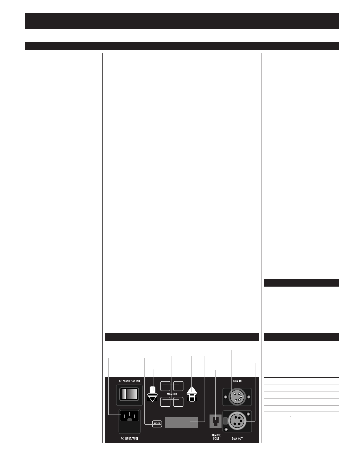
AC Power
Switch
Up
arrow
LED Display
Remote
Port
DM In
DM OutDown
arrow
MEMORY
buttons
AC
Input/Fuse
MODE
Key
Phase Dimmable Models
Phase Dimmable models do not have
dimmmers installed inside. Instead they have
the ability to be dimmed via an AC powered
phase dimming system.
Plug the AC cable of fixture into dimmer and
power the fixture up, to control via the dimmer.