Lumacell LER3000 Series User manual
Lumacell Tel: (888) 552-6467 ext. 547 or 255 Fax: (888) 867-1565 www.lumacell.com 06/04 750.1048 Rev. B
1/4
LER3000 Series – Polyvinyl Exit Sign
LER3000 Series – Polyvinyl Exit Sign
AC/DC & Self-Powered Models
IMPORTANT SAFEGUARDS
When using electrical equipment, basic safety precautions should
always be followed including the following:
READ AND FOLLOW ALL SAFETY
INSTRUCTIONS
1. Do not let power supply cords touch hot surfaces.
2. Do not mount near gas or electric heaters.
3. Use caution when handling batteries. Avoid possible shorting.
4. Equipment should be mounted in locations and at heights where it
will not readily be subjected to tampering by unauthorized personnel.
5. The use of accessory equipment not recommended by the manufac-
turer may cause an unsafe condition.
6. Do not use this equipment for other than intended use.
7. All servicing should be performed by qualified service personnel.
SAVE THESE INSTRUCTIONS
Installation Instructions
1. Turn off unswitched AC power.
Canopy Mount
a. Remove canopy assembly from carton. Remove mounting plate
from canopy and retain securement screw.
b. Route unswitched AC circuit wires into the junction box and leave
6” of wire length.
c. Remove proper knockouts in canopy backplate for desired
mounting position.
For Nexus option, install the liquid tight fitting, provided with the
unit. For Ceiling mount, use the k’out located on side of the unit
(opposite side of the diagnostic display). For Side mount, use the
k’out located on top of the unit (see fig. 4).
d. Feed unswitched AC wires through large hole in canopy mount-
ing plate.
e. Make sure the securement screw is accessible (see fig.1 part #
13). Use existing screws in junction box to secure canopy back-
plate to the junction box.
f. Remove lens, exit panel and diffuser panel on the front of the unit
(use the supplied bit to remove the tamper-proof screws).
g. In order to access the knockouts of the frame, remove the 4 elec-
tronic module screw(s) holding the electronic module to the frame
and separate them (see fig.2).
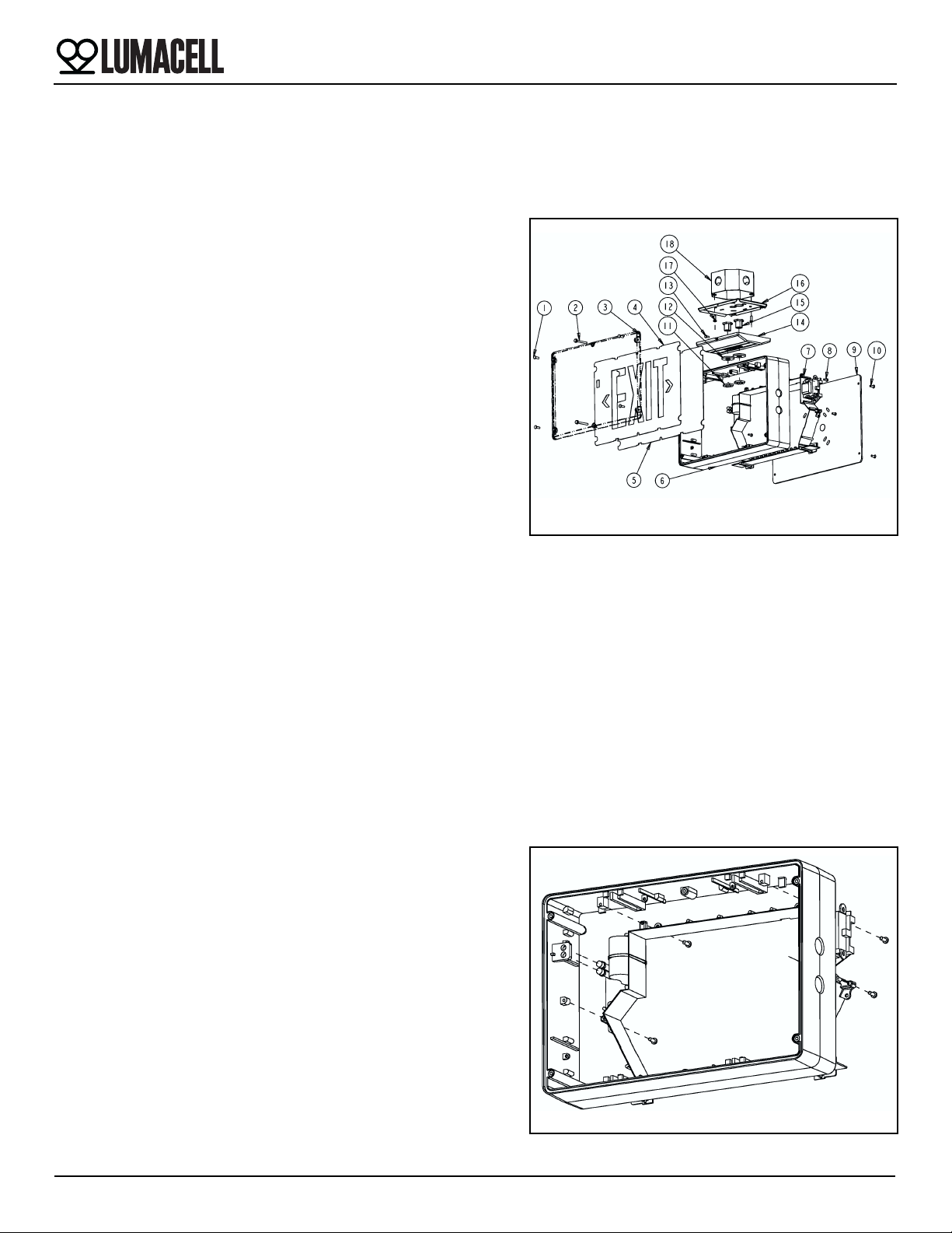
Figure 1
Part List
1. Tamper-proof screws short
(4 per lens)
2. Tamper-proof screws long
(2 per lens)
3. Lens
4. EXIT panel
5. Diffuser panel
6. Frame
7. Electronic module
8. Electronic module screws
(4)
9. Backplate (single face sign)
10. Backplate tamper-proof
screws (4)
11. Lock-nuts (2)
12. Gasket washer (2)
13. Canopy securement screw
14. Canopy
15. Nipple assembly (2)
16. Canopy backplate
17. Junction box screws (not
supplied)
18. Junction box (not supplied)
19. Nylon washer (2 for wall
mount)
20. Junction box gasket (for
wall mount)
Figure 2
LER3000 Series – Polyvinyl Exit Sign
2/4
Lumacell Tel: (888) 552-6467 ext. 547 or 255 Fax: (888) 867-1565 www.lumacell.com 06/04 750.1048 Rev. B
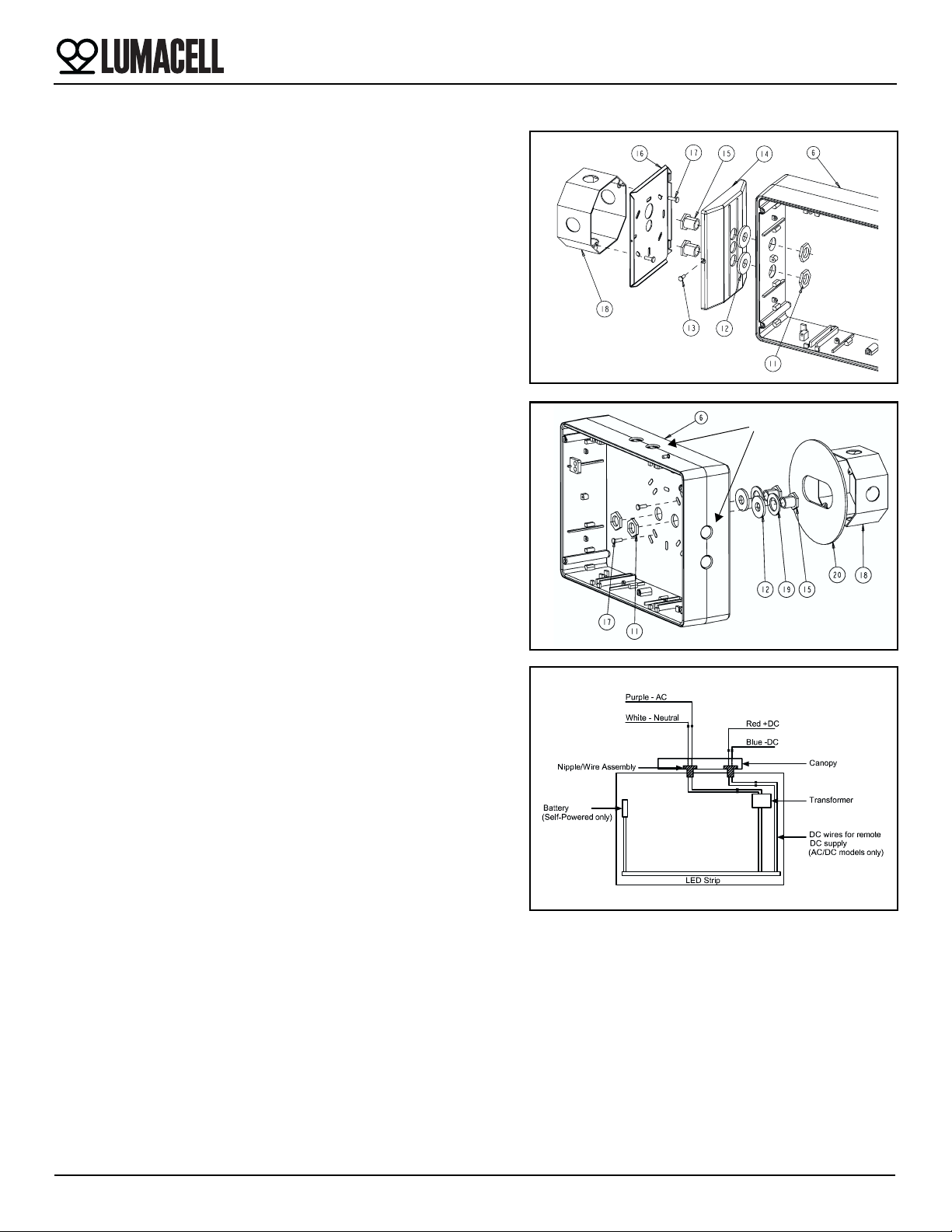
h. Determine which holes in the exit frame will be used for mounting
(see fig.1 & fig.3). Support frame by two blocks of wood, maxi-
mum one inch apart. Strike knockouts with a hammer and screw-
driver. Clear holes of burrs to allow proper assembly of nipple/
wire assembly.
i. Secure canopy to the frame using the provided nipple/wire
assembly. Make sure the gasket washers are between the can-
opy and frame, and the nuts inside the exit sign (see fig. 3).
j. Reassemble the electronic module inside the frame.
Wall Mount (Single Face Model Only)
a. Remove the backplate from the packaging. Determine the proper
knockouts to remove for mounting to a junction box (see fig.4).
For Nexus option, install the liquid tight fitting, provided with the
unit (see fig. 4).
b. Support area around knockouts with two blocks of wood. Strike
knockouts from the inside with a hammer and a screwdriver.
c. Mount parts 11, 12, 15, 17 & 19 to backplate, as shown in fig. 4,
and reinstall the backplate to the frame using the 4 tamper-proof
screws (use the supplied bit).
2. Electrical connections: Using the sealed AC nipple/wire assembly
(3 wires), connect one end to the transformer leads, inside the enclo-
sure, and the other end, to AC line voltage inside the junction box.
Connect the white lead to neutral and the purple lead to AC line volt-
age (the input is universal 110 to 347 VAC). (See fig. 5).
Optional: For AC models used with DC remote power, the sealed
DC nipple/wire assembly (2 wires) will also need to be installed. One
end connects to the LED-STRIP leads, inside the enclosure, and the
other end to DC input inside the junction box. Connect the red lead
to positive, and the blue lead to the negative of the remote DC input
(See fig. 5).
3. For canopy mount: Attach the canopy backplate to the junction box
using the junction box screws. Mount the frame and canopy assem-
bly to canopy back plate by using the provided securement screw.
For wall mount: Attach the frame to the junction box, using the junc-
tion box supplied screws.
4. Reinstall the diffuser and the EXIT panel (if required, remove the
appropriate chevron).
5. Install the lens by using the 4 short and 2 long tamper-proof screws.
The tamper-proof screws should be equally torqued to approxi-
mately 5 lbs-in (0.6 N-m).
6. Energize AC. Sign will illuminate.
Manual Testing (Self-Powered Models)
Operate the magnetic “test switch” by holding the provided magnet
underneath the unit where indicated on the frame. The AC pilot lamp will
go out, the legend will flicker, but remain lit. Remove the magnet. The
AC pilot light will turn on, the legend will flicker but remain lit.
Automatic Testing (Self-Powered Models)
The unit will perform an automatic self-test of 30 seconds every 30 days,
60 second every 60 days and a 90 minute self-test once a year.
Figure 3
Figure 4
Knockouts
Figure 5
LER3000 Series – Polyvinyl Exit Sign
3/4
Lumacell Tel: (888) 552-6467 ext. 547 or 255 Fax: (888) 867-1565 www.lumacell.com 06/04 750.1048 Rev. B
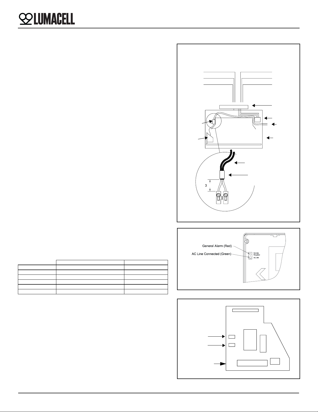
Nexus models
Refer to figure 6 for the wiring of Nexus models.
These units can accept an input voltage of 120 or 347 VAC:
120 VAC — Connect the black (120 VAC) lead and white (neutral) lead
to the building utility. Insulate the red wire.
347 VAC — Connect the red (347 VAC) lead and white (neutral) lead to
the building utility. Insulate the black wire.
Feed excess wire into the junction box.
Leave as much space as possible between the live voltage cabling and
the unsheathed low voltage data cabling.
Run the double insulation of data cables past the line cabling section and
only strip back the last 30mm of the data cable sheathing.
Automatic Diagnostics (Self-Powered Models)
There are three diagnostic indicators: one external and two internal. Unit
must be opened to gain access to internal indicators.
External: General alarm, “Service Required”. The LED will blink if any
alarm condition is detected (see fig. 7).
Internal: Battery Alarm & Charger Alarm. Steady ON if alarm condition
exists (See fig. 8).
Normal operation, No fault — “Service Required” is OFF and one of
the two internal LED blinks, showing that the micro controller is active.
Faulty operation — “Service Required” blinks.
Battery Alarm ON, Charger Alarm OFF: Check battery or replace battery.
Battery Alarm ON, Charger Alarm ON: Check LED strip.
Battery Alarm OFF, Charger Alarm ON: Check charger circuit.
Nexus models
Nexus models use two local indicators. One is a green LED for AC pilot
lamp. The other is a tricolor LED (Service) which identifies and displays
the Nexus status. The table below describes each status:
Nexus Tricolor LED — Status table
Maintenance (All Models)
None required. If AC supply to the unit is to be disconnected for 2
months or more, the battery must be disconnected, Self-Powered Mod-
els only.
Canopy
Figure 6
LED Strip
Nexus data
Black (120)
Red (insulate)
White (neutral)
Black (insulate)
White (neutral)
Red (347)
120 VAC or 347 VAC
Sign
30 mm
Interface
Data
Tape
Nexus data cables
Nexus data
Nexus
Transformer
Nexus model wiring
terminal block cables
Figure 7
Figure 8
Battery Alarm
Charger alarm
Diagnostic board
Uncommissioned Commissioned
Normal Red/Off pulsing Green steady
Under test N/A Green/Off pulsing
Wink mode Yellow-orange/(red or off) pulsing Yellow-orange/Off pulsing
Neuron faulty Red Steady Red steady
Power fail Off Off
Battery disconnected N/A Off
LER3000 Series – Polyvinyl Exit Sign
4/4
Lumacell Tel: (888) 552-6467 ext. 547 or 255 Fax: (888) 867-1565 www.lumacell.com 06/04 750.1048 Rev. B
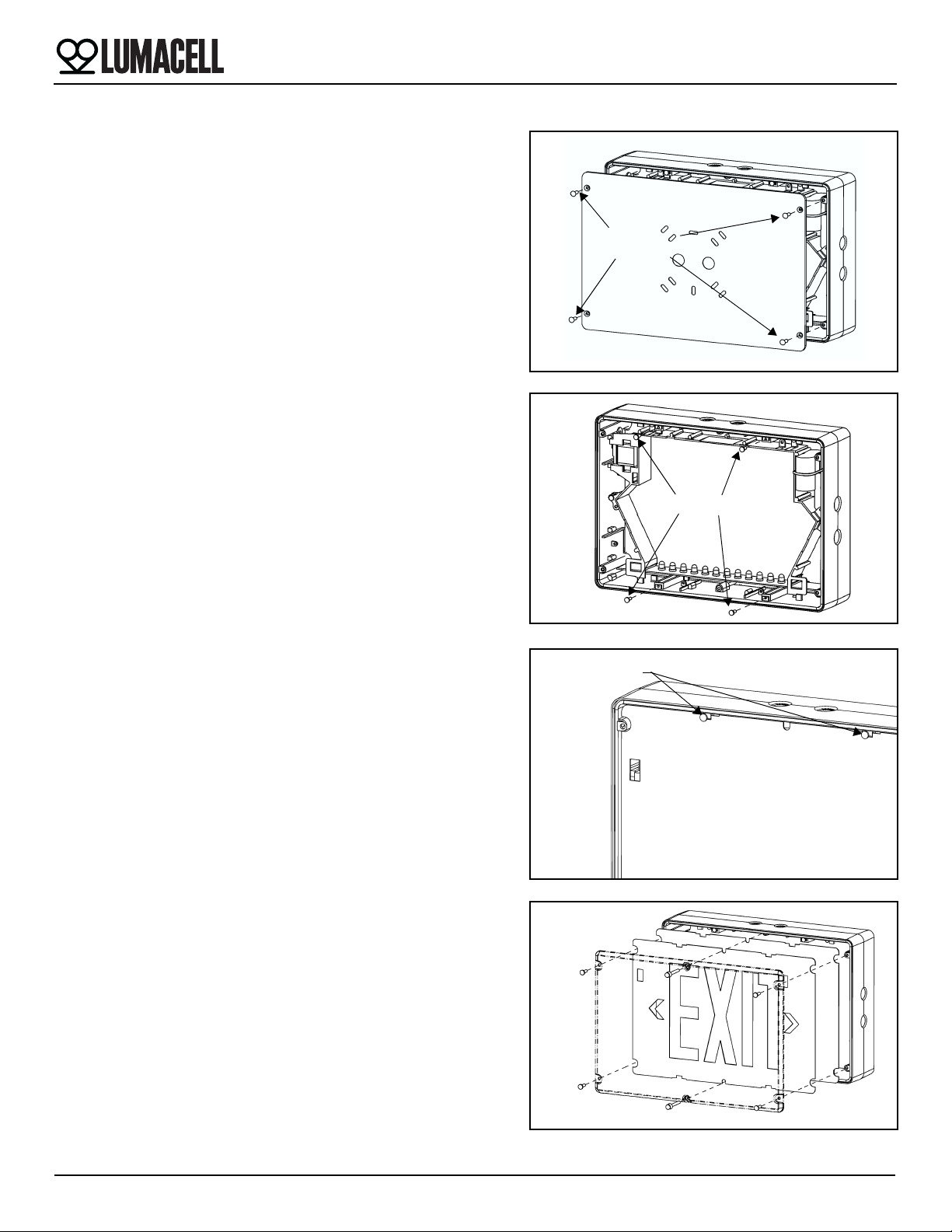
Double Face Installation
Installation Instructions
1. Turn off unswitched AC power.
2. Remove backplate by unscrewing the four tamper-proof screws hold-
ing the backplate to the frame (see fig. 9)
3. Install the four backpanel retention screws (see fig. 10)
Note: The four screws may already be installed.
4. Install the diffuser panel by snapping the top edges under the two top
retention screws and then snapping the bottom edges under the two
bottom retention screws (see fig.11).
5. The EXIT panel installs in the same manner (if required, remove the
appropriate chevron).
6. Install the lens by using the 4 short and 2 long tamper-proof screws
(see fig.12).
The tamper-proof screws should be equally torqued to approxi-
mately 5 lbs-in (0.6 N-m).
7. Energize AC. Sign will illuminate.
Figure 9
Backplate
screws
tamper-proof
Figure 10
Backpanel retention screws
Figure 11
Snap panel under
these screws
Figure 12


