WARNING:
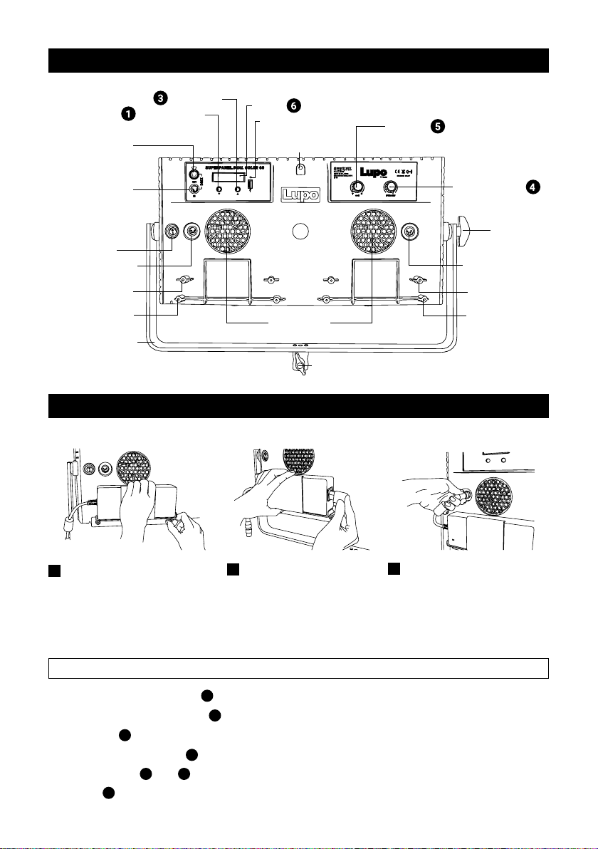
When hanging the xture from higher position, please make sure you use safety cable to
attach the barndoors to the yoke of the panel.
Barndoors should always be used to secure the xture and the application when used in this
way.
Another safety cable should be used to secure the xture to the mounting pipe or truss.
Both safety cables must be properly dimensioned for the xture and the application when
the xture is operated in hanging position please ensure that the accessories are installed
correctly with top latch locked.
SAFETY PRECAUTIONS:
Do not operate the equipment before studying
the instruction manual and the accompanying
safety precautions. Make sure that Lupo
Safety Instruction is always included with
the equipment! Lupo products are intended
for professional use. Do not place or use
the equipment where it can be exposed to
moisture, extreme electromagnetic elds or in
areas with ammable gases or dust! Do not
expose the equipment to hasty temperature
changes in humid condition as could lead to
condensation water in the unit. Equipment
must only be serviced, modied or repaired by
authorized. Dealers or the factory.
CAUTION - BURN HAZARD - HOT PARTS
Do not touch hot parts with bare ngers! LED
bulbs and certain metal parts emit strong heat
when used!
Do not point lamps too close to persons.
Always use the xtures with the front part
closed.
NOTICE - EQUIPMENT OVERHEATING RISK
Do not obstruct ventilation by placing lters,
diffusing materials, etc. over inlets and outlets
of the equipment ventilation or directly over
glass cover or LED bulbs.
FINAL DISPOSAL
Equipment contains electrical and electronic
components that could be harmful to the
environment.
Equipment may be returned to Lupo distributors
free of charge for recycling according to WEEE.
Follow local legal requirements for separate
disposal of waste, for instance WEEE directive
for electrical and electronic equipment on the
European market, when product life has ended.
MAINTENANCE AND CARE
Please do not forget that the safe operation of
lampheads also includes their maintenance
and care.
A visual inspection should be conducted before
every use and an inspection of electrical safety
should be conducted at least once every 12
months.
WARRANTY
The warranty period for Lupo products and those
marketed by Lupo is twelve months from the
date of delivery. Lupo guarantees that the goods
it supplies are well manufactured and of good
quality. The warranty guarantees the repair of
any parts that show acknowledged defects in
materials, construction or workmanship during
the warranty period. The guarantee excludes
any liability for direct or indirect damage of any
kind and for any reason, for which Lupo will
therefore not be required to pay compensation.
The customers shall see to deliver the parts
that need repair or replacement to Lupo’s works
at their own expense and risk. The repaired or
replacement parts shall be delivered by Lupo
ex-works. The customers will be charged for
materials and labor or replacement of the
product after the expiration of the warranty
period.
Thanks for having purchased Lupo products. All the products are made in Italy and all the efforts
have been put to keep the quality standards high. We hope this product can help you in your job and
make your life easier as a professional. We also hope you will enjoy its use and we would be happy to
receive your feedback about it.
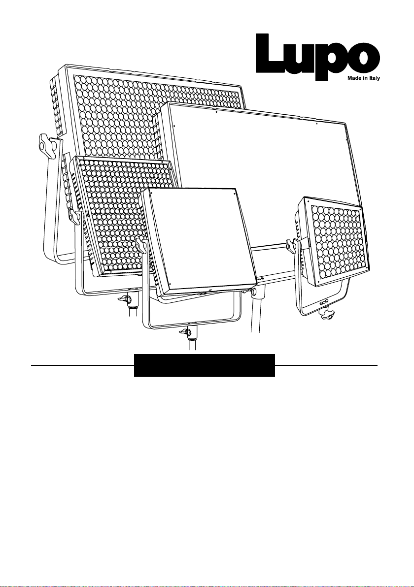
Superpanel 30 Dual Color
Superpanel 60 Dual Color
Actionpanel Dual Color
Ultrapanel 30 Dual Color
Ultrapanel 60 Dual Color