5
INTEGRATED AMPLIFIER L-507Z
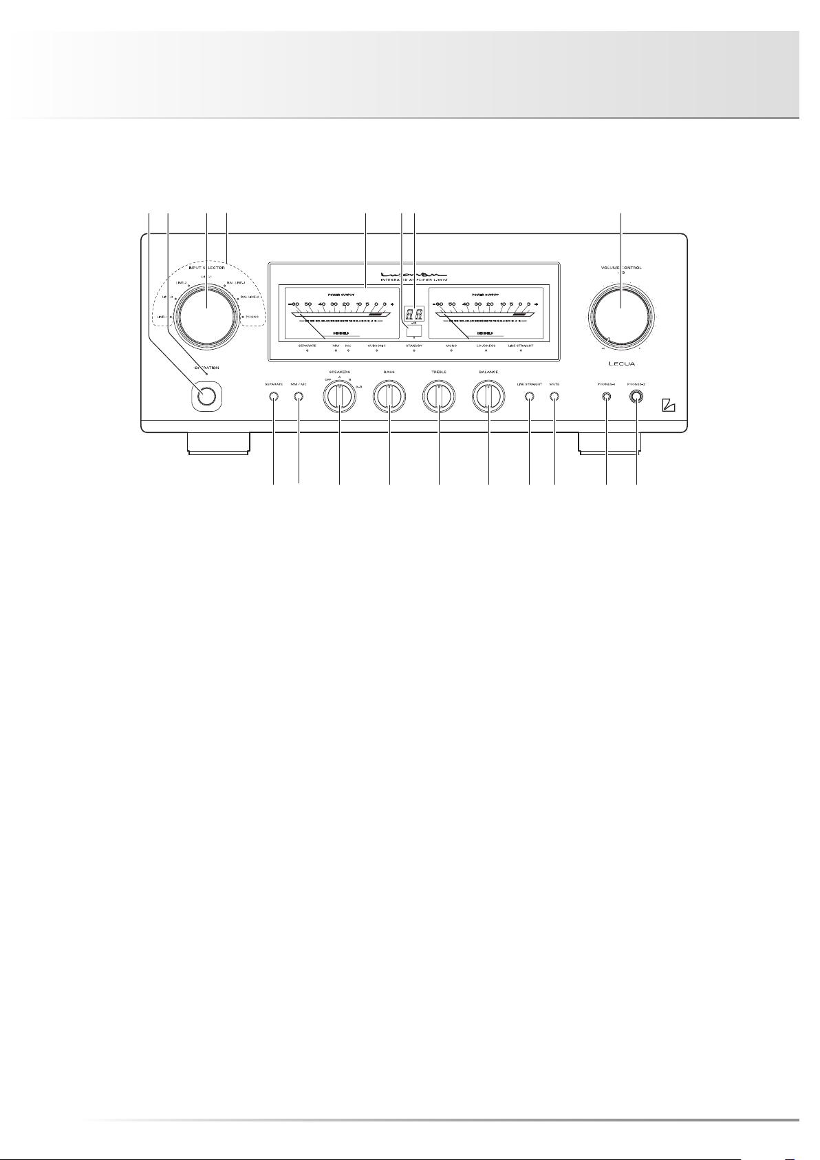
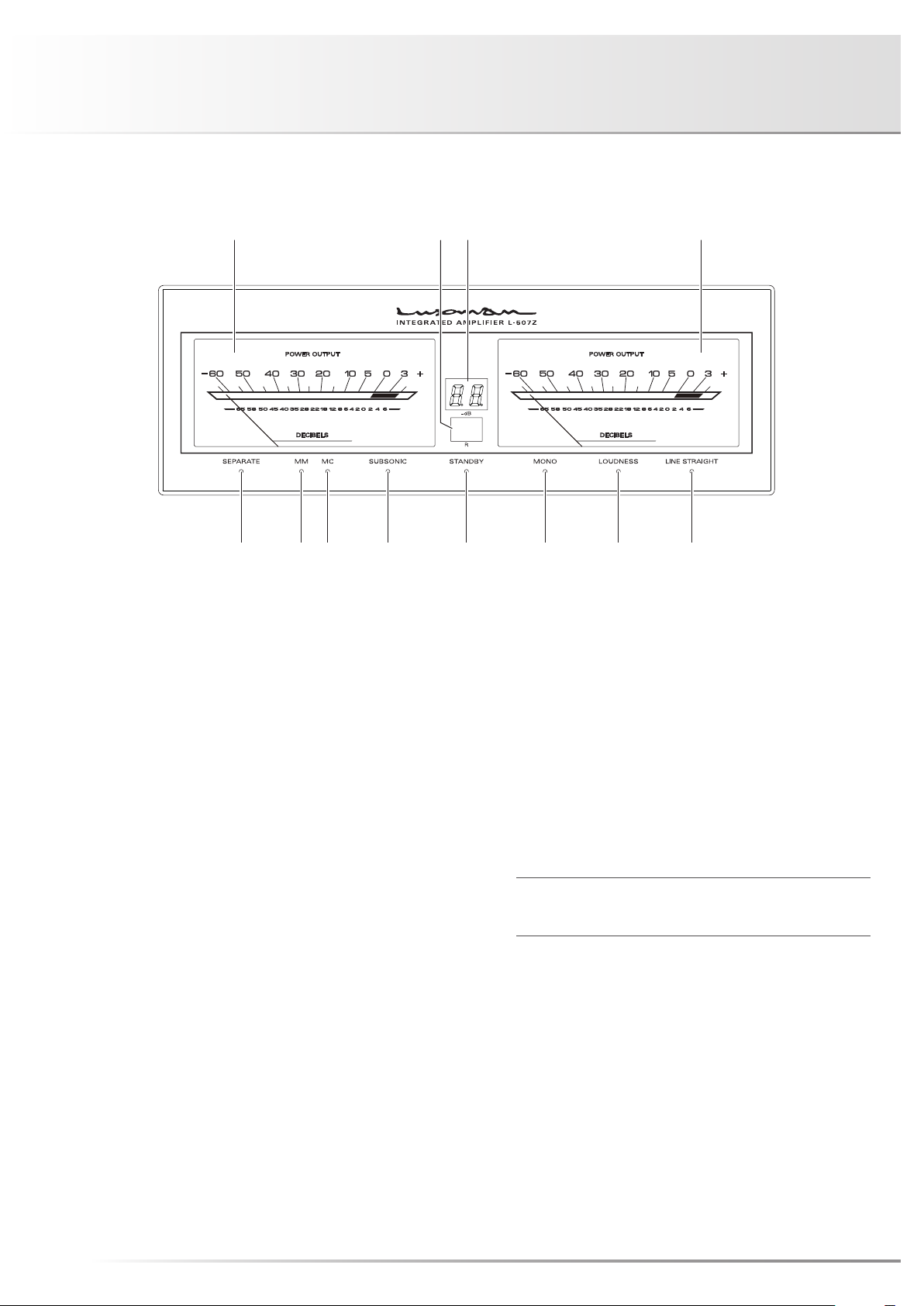
5. Display window
Displays the operation status of this unit.
This display is composed of 8 indicators, sound volume in-
dicator, and 2 power meters.
6. Remote control infrared receiver (R)
Receives signals from the accessory remote control.
7. Sound volume indicator
Indicates the amount of volume attenuation in –dB.
8. Volume control (VOLUME CONTROL)
Adjusts the sound volume.
Sound will not be heard when this control is rotated ful-
ly counterclockwise. Volume will gradually increase as the
control is rotated clockwise as follows: mute →–87 dB →
–86 dB →... →0 dB in steps of 1 dB.
9. Phone jack (PHONES-2)
Insert your standard 6.3mm headphone plug into this out-
put jack when listening with stereo headphones. Even when
a headphone jack is inserted, signals to the speaker output
terminal are not interrupted. To listen to music using only
your headphones, set the speaker selector to OFF.
10. Phone jack (PHONES-1)
This jack is an output jack to be used with a 4.4mm stereo
headphone plug.
Even when a plug is inserted in the same way as PHONES-2,
signals to the speaker output terminal are not interrupted.
The PHONES-1 (di. 4.4) phone jack of this unit is a ground
separation type connection model with an unbalanced
amplifier.
Connection of compatible headphones allows you to enjoy
listening with high separation performance thanks to inde-
pendent wiring of right and left (-) signals.
11. Mute button (MUTE)
When this button is pressed and the mute function is
activated, the operation indicator will start blinking and there
will be no audio output.
Pressing this button again sets the mute function to off.
12. Line straight button (LINE STRAIGHT)
Enhances the purity of the sound quality by bypassing cir-
cuits such as balance control and tone control.
OFF (Line straight indicator off):
Line straight off/bypass off
ON (Line straight indicator on):
Line straight on/bypass on
• This button toggles the line straight function on and off.
The line straight indicator lights up when the line straight
is set to on.
When the line straight button is set to on, the balance
control, tone control, subsonic, monaural and loudness
cannot be adjusted.
13. Balance control (BALANCE)
Adjusts the balance of sound volume between right and left
channels.
Rotating the control counterclockwise gradually cuts the
volume of the right channel, rotating the control clockwise
gradually cuts the volume of the left channel.
This knob should be set to the center position under normal
conditions, and rotated to make adjustment if necessary.
When the line straight button is set to on, this control cannot
be adjusted.
14. Tone control for treble TONE CONTROL
(TREBLE)
Controls the frequency characteristics of the high-frequen-
cy range.
Setting this control to the center position provides flat fre-
quency characteristics. Rotating this control clockwise en-
hances the high-frequency range, and rotating this control
counterclockwise attenuates the high-frequency range.
When the line straight button is set to on, this button does
not function.