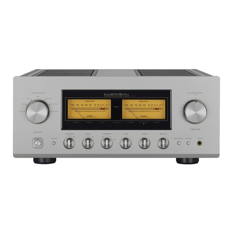
Luxman C-383 User manual

Stereo Preamplifier
OWNER'S MANUAL
BEDIENUNGSANLEITUNG
MODE D'EMPLOI
MANUAL DE
OPERACION
LIBRETTO DELLE ISTRUZIONI


ReferenceIllustrations
.............................................................................................................
4
Introduction
...............................................................................................................................
6
.............................................................................................................
Connection Guidelines 7
Names
&
Functions of Parts
....................................................................................................
8
Operation Guidelines
..............................................................................................................
12
Care and Maintenance
............................................................................................................
15
In caseof Difficulty
.................................................................................................................
16
Specifications
..........................................................................................................................
17
Abbildungen
..............................................................................................................................
4
Vor der lnbetriebnahme
..........................................................................................................
18
AnschluO
..................................................................................................................................
19
Bezeichnungder Teile und Funktionen
................................................................................
20
Bedienung
...............................................................
:
................................................................
24
Wartung und Pflege
................................................................................................................
27
Im Storungsfall
........................................................................................................................
28
Technische Daten
....................................................................................................................
29
Illustrations de Reference
........................................................................................................
4
Introduction
.............................................................................................................................
30
....................................................................................................
Directives de Branchement 31
Nomenclature
..........................................................................................................................
32
Directives de Fonctionnement
..............................................................................................
36
Soin et Entretien
......................................................................................................................
39
En cas de problemes
..............................................................................................................
40
Specifications
..........................................................................................................................
41
......................................................................................................
lllustrationes de referencia 4
lntroducction
...........................................................................................................................
42
.....................................................................................................
Guias para las conexiones 43
.................................................................................
Nomenclatura funciones de las partes 44
Guias para la operacion
.........................................................................................................
48
Cuidados
y
mantenimiento
....................................................................................................
51
En caso de dificultad
..............................................................................................................
52
Especificaciones
.....................................................................................................................
53
lllustrazioni di riferimento
........................................................................................................
4
lntroduzione
.............................................................................................................................
54
lstruzioni sul collegamento
..................................................................................................
55
Nomenclatura efunzioni delle parti
.......................................................................................
56
lnformazionisul funzionamento
............................................................................................
60
Cura e manutenzione
..............................................................................................................
63
In
caso di problemi
..................................................................................................................
64
Dati Tecnici
..............................................................................................................................
65

Fig.
1IAbb. 11III. 1
.Speaker Syste'i;s
T,jner
-
T,,ne, liloni:or TV Lauls~rerne.oc~en
.Totier .Mori:or Systemes d e~,ie,.itas
.
S~nto!i,zadar .Mon~:r?,~rTV S~slcrr~,isdc!
n
aces
.
Sinton~zza!ore Televisor nonilor S1s1err.lall~~,lil~.lI~
Taev~sore
----------
/
0
I(--
00
)
.RC-50; Sensor :Eye) Locate in a Rrmole Roonl
.
L.e'!unilsausgang
Soole de ligne
.Sn iaa de lhneh
.
!Jsc,ta
;q
11nt.i:
Povjer Arnpilf
I:
.Enduerslarker
A~~piIicateurde pu~ssar~:e
Usct;i in lnea Ampll~cadarde polencla
Arnol~'~cztore
CI
oaterza
d al~mi.n!o'~o:~
secteili
.Le~~urlgsausgang Cdbe dl: CA
Lcne
iii
Sort e de Igne Lared CA
.Lettungzelngang .Salida de iinea
En:ree de kgne Usclta in !.lea
En!rada de l~nea
.
Ing'esso n lbnea
.Line
In lineOut
.Ll.lU Out
.
ie~lungsririgang Le~lurigsnu!,ga~ig
.
Ta,?:abi+, .Leil;irigsausgC3r~g Eritrce de Ibgr;e Sorte de Iigrle
P1a:lersp~ler Sortie
ds
lane .Entrada da hnea .Sai~ddde linea
P1al'r.e lod~npd-qbe Sallda de lhlea ngresso
11
lhnaa
IJsc,:a
tn
llnea
G
r~dscos ?Js~t~i
~n
llrea
.G~tad!scr~
I
tiliii
fi
tiiiti
]
.
Lfne Our
.Le~lurigsa~sgarg
Sortie de Ihgne
Saljda de (Pea
u
U
Sraphic Equal~ze:elc
GraphicEgaliseurEqoal:zergraphrqueus5.#(etc
i
Ecdallzcor gralico elc
0,
-
Uscila
I-
lnea
fl
Tape Deck
7
U
Line In
Laser Dtsc Pldyer
.
Lnsa;~Bi!dolal:erisp~elar
.Lellunpselngang
Locleui dedsques laser .Entreede Igre
.Reproductor de dlscos laser Eritrada de Ihii~a
ieliore di laserd~sc lngresso ~nIine,i
-
C;issnllendeck
PP.atre
a
!:assi?lte
Deck de
CRSBICS
.
~1.3strda r:dssetre
CD Pldye,
CD Pidyer
0
I1
n
~ecteur
CD
Reproductor de
-
Llne Out Equaiiz:atore grdlco (ecc
:
.Leitungsausgang
Sortie de l~gne
Sallda do Irea
-
Usci!a in Inea
U
d~scosLanlpaclos
.l.c:l:ore
CD
u
u
On
0
-1
GU
--
0
00

Fig.
2iAbb. 21111.
2
System "BUS" and AC cord connections for "BUS"operation.
illustration
shows a typical combination example.
'.BUSLINE"-Systernanschlusse und Netzanschlusse fur den '-BUS"-Systernbetrieb.Die Abbildung zeigt ein typisches Kombinat~onsbeispiel.
Branchements du systeme "BUS" et du cordon d'alirnentation secteur pour une utilisation "BUS'. L'illustralion indique un exernple de
cornbinaison caracteristique.
Conexiones del sisterna "BUS"y de 10s cables de al~rnentac~onde CA para la operacion del sisterna "BUS". En la ilustrac~onse muestra un
ejernplo decornbinacion tipico.
Colegarnenti del sisterna "BUS" e del cavo di alirnentazione per I'operazione "BUS". L'11iustrazionernostra un esernplo dl cornb~nazione
tlplca.
CD Player
CD-Player
Lecteur CD
Reproductor de
discos cornpactos
Lettore CD
to a wall outlet
an elne Wandsteckdose
a une prise secteur
una torna de la red
ad una presa di rete
Tape Deck
-
Cassettendeck
Piatme
a
cassette
Deck de casetes
P~astraa cassette
Fig.
31Abb. 31111. 3
lnnerhalb
I
.
within
l6
feet
(5
rn)
5
rn
$
Distance inferieure
B
16
pieds (5rn.)
Distancia ~nferiora
5
metros
(1
6
p~es)
Entro
5
metri
Fig.
4lAbb. 41111.4

When You Open the Box
Welcome!
At Luxman, Ultimate Fidelity is a goal we consider
most important. Yourpurchase of this component
has told us you feel the same. We take great pride
in the long tradition of excellence in sonic quality
that the Luxman name represents. Now, as part of
that tradition, we welcomeyou to thegrowing
number of discerning audiophiles who own and
operate Luxmanproducts. This manual has been
prepared to help you maximizeyour enjoyment of
the outstanding performance and feature capa-
bilities of your new Luxman
C-383.
Thisstereo preamplifier represents a novel con-
cept in system and design technology for simpli-
fiedsystem operation and high sonic quality. It
has System Bus, multi-room capability, full system
remote control, motor driven volume control,
Video Input/Outputjacks and LINE straight
...
are
some of the items that combine to achieve this
goal.
Torealize the exceptional performance for which
this Preamplifier is capable, it is necessary that all
signal sources,power amplifier and speaker
systems used with it are of the highest sonic
quality. Werecommend complementary Luxman
components whereverpossible.
Please study this manual carefully and become
acquainted with all the special features, operation
and capabilities of your new Luxman
C-383.
Shouldyou have any questions or desire informa-
tion on other Luxman products, please contact
your local Luxman dealer.
Beforeany Luxman product leaves the factory
it is carefully inspected for physical imperfec-
tions as a routine part of Luxman's systematic
quality control. This, along with full electrical
testing, should insure quality craftsmanship and
performance.After you have unpacked the unit.
inspect it for any physical damage. Save the
shipping carton and all packing materials, as
they are essentialto reduce to a minimum the
possibility of transportation damage, should the
product ever need to be shipped again.
In the unlikely event that damage has occurred,
notify your dealer immediately and requestthe
name of the carrier so that a written claim to
cover shipping damages can be initiated.
The right to any claim against
a
public
carrier can be forfeited if the carrier is not
notified promptlyand if the shipping carton
and packingmaterial are not available for
inspection.Save all packing materials until
the claim has been settled.
Installationand Placement
The Luxman
C-383
generates almost no heat,
therefore its placement is not critical. However
it should not be placed on top of or completely
enclosedwith high power amplifier. If placed in
a cabinet with such components, be sure
adequate ventilation is provided. With these
considerations implemented, the Luxman
C-383
should provide exceptional performance
inany reasonable environment.
Of course, such normal considerations as
protectionfrom excessive dust and moisture
should always be observed. The Luxrnan
C-383
Preamplifier has been carefully designed
with h~ghquality components so that longterm
undiminishedperformance may be expected
when it is operated in accordance with the
instructions provided.
Before Making Connections
It is always wise to ensure that all AC power cords of
the various components that you are interconnecting
are unplugged fromthe wall outlets during the hook-
up process.This will prevent any inadvertent damage
to your speakers or amplifier from incorrect control
settings or connections.
Interconnecting Leads
Be sure that left and right channel identification is
correct when making interconnections.Most patch
cords are colour coded with RED ends for the right
channel and BLACK or WHITE ends for the left
channel, to makethis job easier.
In addition, all jacks on the rear of the C-383 have red
centres for right channel and white for left channel.
When making connections, follow the Reference
Illustrationon page
4,
referringalso to the descrip-
tions for items #27 through #45 on pages 10 and 11.
Power Amplifier Connections
Connect the "PRE OUT"jacks of the C-383to the
Input jacks of your power amplifier with phono type
patchcords.
Ifthe Luxman power amplifier M-363or M-383 is
used with the C-383, connect it to the "TO POWER
AMP" jack on the rear panel of the C-383.Refer to
the owner's manual of the power amplifier for details.
Note on the Signal Processor Jacks
-
Keep the jumper bars inserted when the "SIGNAL
PROCESSOR" jacks are not inuse.
If
the jumper
bars are removed, there will be no sound output.
Removethe jumper bars only when connecting a
graphic equalizer or signal processorto the "SIG-
NAL PROCESSOR"jacks.
AC Power Cord
Insert the AC plug of the C-383 into an appropriate
wall outlet.
SYSTEM
REMOTE
JACK CONNECTIONS
Bus
Line Jack
To control "SYSTEM BUS" equipped models (such
as a Luxman D-373CD player and a K-373tape
deck) connect them to this jack. Connect the audio
leads of the tape deck to the Tape-1 inputs and
place the "TAPE-IITAPE-2"switch on the back
panel of the tape deck to the Tape-1 position.
For remote operation of two
BUS
equipped tape
decks, you may connect the audio leads of one to
the Tape-1 inputs and the other to the Tape-2
inputs. Place the "TAPE-IJTAPE
2"
switch on the
back panel of the first deck to Tape-l position and
the second to Tape-2.The two decks can then be
selected by the Tape-l:Tape-2 switch on the C-383
(item
#5)
or the RA-383remote control (item#19).
When interconnecting source units, the mini phone
cables may be inserted into either jack (thecontrol
signals are bidirectional, therefore no
"IN
OUT
protocol is required).
Plug the AC power cords of each unit included in
the "BUS"system into wall AC outlets.
"SYSTEM BUS,"indentified by the symbol
printed on the carton and owner's manual of the
unit, indicates the Luxman models that work with
the "BUS LINE"jacks on the rear panel.
EXT
REMOTESENSOR
In
Jacks
These 2 jacks may be connected directly to Luxman
RC-501 Infrared Remote Sensor "eyes,"located in
other rooms, via standard coaxial cable (RG-6is
recommended). This allows all remote functions to be
controlled from other rooms as desired, or, in the
same room if the C-383 is placed behind closed
cabinet doors.
Up to six RC-501smay be connected to the C-383 if
a DC pass 3-way splitter (suchas PHILMORE CS14)
is usedat each sensor input.
Repeater Output Jack
This repeater jack may be connected directly to a
Luxman RC-503 IR repeater unit, also via standard
coaxial cable. Remote control of non Luxman units,
such as a VCR, may then take place through the
C-383 remote system.
Note:
Place the C-383so that its remote sensor will not
receive the signals transmitted fromthe RC-503.

Front
Panel
1
2
1.
"POWER" button
Pressing this button turns the unit on and off.
When this button is depressed, the time delay
muting circuit isturned on, putting the amplifier
into perfect operational condition in about
5
seconds.
2.
"stand-by" indicator
This indicator shows that the unit is ready to receive
remote control commands and will stay lit at all
times as long as the power cord is plugged in.
3.
"LINE STRAIGHT" button and indicator
Press this button to bypass control and switching
functions.
4.
\nput Se\ect indicators
The LED indicator for the selected input source will
light up to tell which source is selected with the
Input Select buttons (item
#5).
5.
lnput Select buttons
Press one of these buttonsto select any one of
eight sources; CD. TUNER, PHONO, TAPE-1,
TAPE-2.LD.
AV
and VCR.
6.
"VOLUME CONTROL"
Allows precision,low noise adjustment of volume
level. It is recommendedthat the volume control be
set to a low position prior to power turn on and
when switching between sources.
7.
"loudness"button
Depressingthis button introduces a moderate
boost of the very low and high frequencies when
the volume control is set below the half-way
position. This compensates for the humanear's
characteristic at low listening levels.
8.
"attenuator"button
Press this button to reduce the volume level to
111
0
of the current level.
9.
"balance"control
Adjusts for unequal volume level between chan-
nels. Normally,with today's high quality sources,
it is seldom necessary to move this control from
its precision centre detent position.
10.
"mono" button
Place inthe mono (in)position for mono sources,
for balance control adjustment, for lower noise
operation from high noise stereo source: or for
checking speaker phasing. Otherwise, leave it in
the stereo (out)position.
11.
"remote sensor"
When using the hand held remote control, it
must be pointed toward this sensor to activate
operational functions.

"Continuous play" button and indicator
When this button is depressed during cassette or
CD play, the cassette deck or CD player will
continue to operate even when the lnput Selector
is switched. However,you can hear the sound of
the selected source with the lnput Selector.
"treble" control
This control will increase or decrease high fre-
quency content in the program material.At the
centre detent position, a flat frequency response
results.
"bass" control
This control will increase or decrease low fre-
quency content in the program material. At the
centre detent position, a flat frequency response
results.
15. "REC OUT SELECTOR" switch
This
8
position rotary switch selects any one of 5
sources. AV. LD, phono, tuner and CD, to be fed
to the "REC OUT" jacks of both tape
1
and tape 2
for recording purpose. And two tape dubbing
positions, tape-1
b2IVCR and tape-2
b
1IVCR,
are also selectable. All of these recording opera-
tionscan be performed independently of any
selected source that you may w~shto listento at
the same time.
Set it to the off position, when recordings or dubs
are not being made.
16. "CD synchro" button and indicator
CD play and tape recording can be started
simultaneously by simply pressing the "CD
synchro" button. Inaddition the LED indicator will
blink.
Notes:
CD Synchro only works with a BUSconnected
system.
The "REC OUT SELECTOR" switch (item#15)
must be in the "CD" position.
Remote Control Unit
(RA-383)
18. "SLEEP" button
19. "TUNER CDITAPE-1 TAPE-2" Select switch
20. "TUNER" Station Presets1"CD" Direct Access
buttons (1
-
10 and +lo)
21. CDITUNER Control buttons
22.
Tape Deck Control buttons
23. "VOLUME UPIDOWN" buttons
24. "MUTE" button
25.
"DIMMER" button
26. "RESET" (dimmer) button
17. "phones" jack
Connection of stereophonic headphones to this
jack allows private listening. There is signal at the
jack at all times.

Rear
Panel
27.
"LD (AUDIOiVIDEO)"lnput
jacks
Connect the video and audio output terminals of
a laser disc player to these jacks.
Note:
See Reference Illustrations, page 4, for typical con-
nectionsto all jacks and terminals (items
#27
through
45).
28. "AV (AUDIOIVIDEO)" lnput
jacks
Connect the video and audio output terminals of
a video deck or laser disc player to these jacks.
29.
"VCR IN
and
OUT (AUDIOIVIDEO)"
jacks
Connect the video and audio outputlinput termi-
nals of a video deck to the
VCR
INIOUT jacks on
the C-383 respectively.
30.
"TV MONITOR OUT"
jack
Connect the video input jack of a TV to the "TV
MONITOR OUT" jack of the (2-383.
32. "EXT. REMOTE SENSOR IN"
jacks
These
"F"
type coaxial connectors are for
connection of Luxman's RC-501 remote room
sensor "eyes." This permits remote control of
a
complete C-383 system from other rooms.
33. Remote Control "BUS LINE"
jacks
Usethese jacks only with Luxman CD players.
Tape Decks and Tuners that are also equipped
with BUS linejacks, such as the D-373 and the
K-373.
When interconnecting these units with the C-383.
the mini phone cables may be inserted into either
of their two BUSjacks (thecontrol signals are
bidirectional, therefore no "IN OUT" protocol is
required).
34. "TO POWER AMP"
jack
When the L.uxmanpower amplifier M-383 or M-
363 is connected to this jack, the power amplifier
can beturned on or off simultaneously with the
C-383.
31.
"REPEATER"
jack
For connection of Luxman's remote control
command repeater, RC-503.

35. "LINE PHASE SENSOR" indicator
When plugging the AC power cord into the wall
outlet, check the polarity of the AC power cord at
this sensor and indicator. When the sensor is
touched after connecting the AC power cord, the
polarity iscorrect if the indicator remains unlit.
If
the indicator lights up, unplug the AC power cord
then plug its other side into the AC wall outlet.
40. "TAPE-2 IN and OUT"jacks
Connect a 2nd tape deck to these jacks in the
same manner as item #39 above.
41. "TUNER IN"jacks
This set of jacks is for connection of a tuner.
They may also be used for any other high level
signal source as well.
Note:
Check the polarity before connecting any sources.
If
you live in an apartment building where the power
supply is floating, the indicator may not change
status.
36. AC Power Cord
Insert the AC plug of the C-383into an appropri-
ate wall outlet.
37.
"PREOUT"jacks
Use these jacks for connection of a power ampli-
fier.
38. "SIGNALPROCESSOR IN and OUT"jacks
For connection of a surround sound processor,
an equalizer or other signal processor as desired.
Note:
Jumper bars are factory installed in these jacks. They
need to be removedonly when connecting a proces-
sor. Retainfor possible future reuse.
42. "CDIN"jacks
This set of jacks is for connection of a CD (com-
pact disc) player. They may also be used for any
other high level signal source as well.
43. "PHONOIN"jacks
Connect a phono turntable equ~ppedwith an MM
(moving magnet) or MC (moving co~l)cartridge.
Set the MMIMC cartridge select switch (item
#44)
inthe matching position.
44. "MM/MCUCartridge Select switch
Use this switch to match with the cartridge type
connected to the (2-383's PHONO INjacks.
45. "GND"terminal
Connect the common (ground) lead of your
phono turntable to this terminal.
39. "TAPE-I IN and OUT" jacks
Connect the LlNE IN and LlNE OUTjacks of your
audio tape deck to these OUT and INjacks
respectiveiy
.

The following guidelines assume that all connections
have been made according to the "Reference Illustra-
tions,"page
4.
Power and Source Switching
To prevent the possibility of excessive, sudden sound
levels, it is recommended that the volume control be
placed at a low level position each time the power
button isturned on or when switching between
sources by the INPUT SELECTORS.
To Play Source Units
1. Turn the power on to all the components in use.
2. Choose your desired source with the lnput Selec-
tor buttons (item#5).
3. Operate the source unit.
TAPE
DECK
OPERATIONS
Tape Recording Operations
To makea tape recording of any source, proceed as
follows:
1. Rotate the "REC OUT SELECTOR" (item #15) to
the source you wish to record.
2. The source signal will now be fed to the tape deck.
Follow the recording instructions for the tape deck
in use.
3.
If
you have a 3 headdeck, you can monitor the
actual recording by depressing the corresponding
"TAPE-1"or "TAPE-2"buttons (item #5) on the
C-383.
Video Recording
To make a video tape recording of any video source.
proceed as follows:
1. Rotate the "REC OUT SELECTOR, (item #15) to
the source you wish to record (LDor AV).
2. The source signal w~llnow be fedto the connected
VCR. Follow the recording instructions for the VCR
in use.
Tape Dubbing
Tape copies can be made from TAPE-1 to TAPE-21
VCR or fromTAPE-2to TAPE-IIVCR as follows:
1. To dub from TAPE-1 to TAPE-2IVCR, rotate the
"REC OUT SELECTOR" (item#15) to the tape-
1b21VCRdubbing position.
2. Place tape deck 1 in the PLAY mode and deck 2 in
the RECORD mode.
3.
If
audio tape deck 2 is
a
3 head machine,actual
monitoring ofthe audio recording can take place
by selecting "tape-2"on the Input Select button
(item #5).
4.
Similarly, to dub fromTAPE-2to TAPE-IIVCR,
rotate the "REC OUT SELECTOR" to the tape-
2.1 /VCR dubbing position.
5. Follow steps (2)and (3)above except remember
decks 1 and
2
are reversed.

Remote Control Operation
To Turn Power ON or OFF
Press "POWER ON/OFFWbuttons (item #I).
Operating the
C-383
To select a desired source, press
a
source button
(item
#5),
CD, TUNER, PHONO, LD,AV. TAPE-1,
TAPE-2 and VCR.
To turn up the volume, press "VOLUME UP" button
(item
#23).
To turn down the volume, press "VOLUME DOWN"
button (item#23).
To mute the sound temporar~ly,press "MLITE"
button (item #24).
To restore the sound, press it again.
(During muting, the volume indicator blinks.)
BUS
SYSTEM
OPERATIONS
Products connected to the "BUSLINE"jack allow
following operations from the RA-383remote control
unit.
Automatic Source Switching and Play of Music
Sources
When
a
source button on the RA-383is pressed, the
corresponding source unit will automatically be placed
in the PLAY mode and be heard Similarly,when a
play button is pressed on a source unit or the tuning
or station preset buttons pressed on the tuner, the
input source selector on the C-383will automatically
be switched to the corresponding source. This feature
works only with Luxman CD players, Tuner and Tape
Decks that are equipped with BUS line jacks.
Operating the Cassette
Deck
The operations in the following table are possible for
either one or two "SYSTEM BUS"decks connected to
the "TAPE-1"and "TAPE-2"jacks. Choose the de-
sired deck with the "TAPE-1nAPE-2"selector (item
#19).
1
To start playback
,
>
To start reverse playback
1-5-
To fast forward to the righthewind
to the right
To fast-forwardto the leftlrewind to
the left
---
-
..
To music search to the right
I-!--
>
or
<
Each time a
>>
or
cc
button is
pressed,a track is added. (Up to
8 tracks in both directions.)
I
>>
To music search to the left
Each time a
>>
or
cc
button
7-
is
pressed, a track is added.(Up to
8 tracks in both directions.)
--
--
To select deck A or
B
-
-.
--
I
To stop playback or recording
,
STOP
--A
To set the cassette deck to record- REC
ing pause mode PAUSE
To record
Pressthe
c
or
>
button, use REC
direction that isthe same as that PAUSE
indicated by the tape direction
indicator on the tape deck.
-
Note:
Location of the switches will be different depending
upon the models connected, so perform operations by
referringto the Owner's Manual for each model.

Operating a
CD
Player
3. Select the Dolby NR mode with the "DOLBY NR"
The following operations are possible. switch (item#B).
Set the "TUNER CD" switch to the CD postion.
To start play
To stop play
.~
-.
Note:
Locationof the switches will be different dependirlg
upon the models connected, so perform operations by
referringto the Owner's Manual for each model.
PLAY
--
STOP BIC button
B NR mode
-
1
C
C NR mode (depressed) (depressed)
-
-
-.-
-
-
-
"CD
Synchro" Recording
TOrecord without
1
OFF
Dolby NR mode
i
(released)
When the C-383 is used with BUS line equipped
source units. such as the Luxman D-373 CD player
and K-373cassette tape deck. synchronized start:
record,pause and stop functions are possible when
making recordings of CDs with the press of a slngle
button. For instance,when the "CDsynchro" button
(item#I
6)
on the C-383 is pressed,the K-373cas-
settedeck will go into record mode and the D-373
begins playing at the same time.
Any
position
To stop play temporarily
+..~
PAUSE
~.
To skip tracks in forward direction
-
-.-A
>>I
To skip tracks in backward direction
1
I<<
-.-
To search a track in forward direction
1
>>
-
~.
-
To search a track in backward direction
:
<<
Use the following procedure:
..
.
-
.
-
.-
To select a disc in a CD changer
1. Set the "REC OUT SELECTOR" (item
#15)
to
"CD."
2.
Insert a tape for recording into the deck (item #A in
a previousdiagramj.
--
DISC SEL
1
I<< >>I
4.
Place the disc in the CD player (item #C).
Recordings can be made to fit the length of the
tape used, if your CD player has an editing func-
tion. For further details, refer to the manual of the
CD player.
5.
Turn "REC LEVEL"control (item #D) to rec and
adjust the recording level.
6. Press "CD synchro" button (item #16) of the
C-383.CD play and tape recording w~llstart
simultaneously. The recording level is indicated by
the level indicator. When +3 lights up on music
peaks,the level is set appropriately.
7. To stop synchronized recording, press the STOP
button on the cassette deck or CD player.
Notes:
CD Synchro recording can only be performed using
the tape deck connected to the "TAPE-1" jacks on
the C-383.
Be sure to advance past the leader tape before
recording. Otherwise, the beginning of the CD may
not be recorded.
Location of the switches will be different depending
upon the models connected, so perform operations
by referringto the Owner's Manual for each model.
To record on both sides using an auto-reverse
deck,start with the front side Recording cannot be
continued from the reverse side to the front side.
Therefore, when the recording on the reverse side
is completed, it stops.
Recording will not start if the playback button for the
opposite direction is pressed when using an auto-
reverse deck.
--

How to Use Sleep Timer
When a tuner with the sleep timer function is
connected to the system control, timer operations are
available.The power can be cut off automatically after
90
-
10minutes. Setting step is 10minutes.
1.
Pushthe "SLEEP" button (item
#18)
during
playback.
2.
Set a desired time by repeatedly pushing the
"SLEEP" button. The time will be changed by
10
minutes step each time the button is pushed.
With the tuner used, various timer playback can be
made. For further details, refer to the manual for the
tuner.
Remote Operations
For reliable operation, use the hand-held remote
control within the basic dimensional area shown on
page
5,
Fig.
3.
Cleaning
The durable finishof the knobs and front panel will
last indefinitely with proper care and cleaning. Never
use scouring pads. steel wool, scouring powders, or
harsh chemical agents, such as lye solution. These
will mar the finish. Clean with a soft, lint-freecloth or
cotton swab slightly dampened with a mild solution of
detergent and
water.
Repackingfor Shipment
Should it become necessary to ship your
C-383
for
any reason, use the original packing materials. If
these are no longer available, be sure that adequate
materials, at least equivalent to the original, are used,
Battery Replacement (Fig. 4, page
5)
1.
Open the battery compartment cover on the rear of
the remote control unit. The cover should open
easily if you press on it with your thumb and slide it
inthe direction of the arrow.
2.
Place two "AA" size dry batteries in the battery
compartment in accordance with the diagram in
the compartment, then replace the cover.
Incorrect use of batteries may lead to leakage or
rupture. Besure to follow these guidelines:
A. Always insert batteries into the battery compart-
ment correctly matching the positive
(+)
and
negative
(-)
polarities as shown inthe diagram
inside the compartment.
6.
Never mix new and used batteries together.
C.
Both rechargeable and non-rechargeablebatteries
are available. Be sure to use your batteries in
accordance with the instructions provided on the
cells.
Repairs
Only the most competent and qualified service techni-
cians should be allowed to service the
C-383.
The
Luxman company and its factory-trained warranty
station personnel have the knowledgeand special
equipment needed for repair and calibration of this
precision instrument.
Inthe event of difficulty, call the Luxman Authorized
Service Station nearest your home or business. In
many cases, the dealer where you purchased your
Luxman unit will be equipped to provide service.

If you encounter a problem, please review the items in amp, speakers, turntable, CD player.TV, cassette
the following checklist. Also, be sure to thoroughly deck. equalizer, etc.
check other connected components,such as power
Check AC power cord to ensure good connection at AC outlet.
PROBLEM
-
--
--
No sound
PROBABLE CAUSE AND SOLUTION
-.
-
-..
--
.
-
-
-
-
-
-
I
I
lncorrect input selected. Check input leads on rear panel (besure they
match input selected).
Line inputs and outputs of a connected tape deck are reversed.
,
SIGNAL PROCESSOR OUTilNjumper bars are removed. Replace.
"VOLUME" control (item
#6)
is set at its minimum position.
I
No record signal.
*
Incorrect settings of "REC OUT SELECTORq'(item#I
5).
..
.
--
-
-
-
~.
I
Remote inoperative
1
Check "AA" batteries. See page1
5.
/
Reset unit. Unplug power cord for
15
seconds. Then replug.

Pre-out Levelllrnpedance (PRE-OUT)
.............................................................
1
.0Vl20 ohms
Total Harmonic Distortion (CD Input):
1kHz: 2 V
.....................................................................................................................
o.oo3°/~
Input Sensitivityllmpedance:
Phono (MM)
..............................................................................................
2.
rnVl47 kohrns
(MC)
...................................................................................................
200 ~1v1100ohms
CD,TUNER. LD. AV, VCR. TAPE-1,TAPE-2
.............................................
150 mVl47 kohms
Video
..............................................................................................................
1 VP-P/75 ohms
Signal-to-NoiseRatio (IHF"A"):
Phono (MMIMC)
.........................................................................................................
91176 dB
CD. TUNER, LD, AV, VCR, TAPE-1. TAPE-2(2V)
......................................................
106 dB
Frequency Response:
Phono (RIAA)
........................
..
.................................................
20 Hz to 20 kHz (+0.
-3
dB)
CD. TUNER, LD,AV, VCR, TAPE-1, TAPE-2
.....................
10 Hz to 100kHz (+0.2.-0.8 dB)
Tone Control Range:
Bass (at 100Hz)
........................................................................................................
,,.?dB
Treble (at 10 kHz)
......................................................................................................
8 dB
Loudness Compensation:
(at 100Hz)
......................................................................................................................
+6 dB
(at I0kHz)
.......................................................................................................................
+4 dB
General
Power Supply
............................................................................................................
230 V. 50 Hz
...............................................................................
Dimensions (W
Y
H
x
D)
438
x
125
x
363 mm
Weight:
(Net)
...............................................................................................................................
7.0kg
(Gross)
........................................................................................................................
8.6kg
Supplied
Accessories
RA-383remote control unit (1)
Size "AA" batteries (2)
Audio phono-plug cord (1
)
Control cord
(1)
Design and specifications are subject to change without notice

LUX
CORPORATION,JAPAN
1-8,1-Chome,Nishigotanda. Shinagawa-ku. Tokyo 141,Japan
Tel: 03-3493-4381 Facsimile: 03-3494-8426
68P21552W76-0
Pr nled 'nJapan
lmpr~meau Japon
Table of contents
Other Luxman Amplifier manuals

Luxman
Luxman P-750u User manual

Luxman
Luxman sq 507 User manual

Luxman
Luxman LV-122 User manual

Luxman
Luxman L-505uX User manual

Luxman
Luxman LV-122 User manual

Luxman
Luxman MQ-300 User manual

Luxman
Luxman LV-117 User manual

Luxman
Luxman L-550AX User manual

Luxman
Luxman C-600f User manual

Luxman
Luxman SQ700X User manual

Luxman
Luxman M-900u User manual

Luxman
Luxman A-371 User manual

Luxman
Luxman 5M20 User manual

Luxman
Luxman SQ507X User manual

Luxman
Luxman L-507Z User manual

Luxman
Luxman L-590AXII User manual

Luxman
Luxman L-550AXII User manual

Luxman
Luxman C-03 User manual

Luxman
Luxman LV-105u User manual

Luxman
Luxman L-505uX User manual