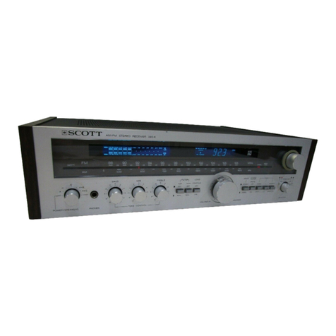
Scott R-316 User manual

price
$6.00
SERVICE
MANUAL
stereo
components
R-316
R-31GL
R-326
1-526
1-526L
®
Ci
SS
C
©)
I
I
_..
where
innovation
is
a
tradition
H.
H.SCOTT,
INC.,
111
Powder
Mill
Road,
Maynard,
Massachusetts
01754,
Tel.
617
897-8801

AUDIO
SPECIFICATIONS
R316,
R326
R316L
Output
Power
R316.
.
20
watts
per
channel
min.
RMS
at
8
ohms
from
40-20,000
Hz
with
no
more
than
0.5%
total
harmonic
distortion,
R326
.
.
30
watts
per
channel
min.
RMS
at
8
ohms
from
40-20,000
Hz
with
no
more
than
0.5%
total
harmonic
distortion.
Input
Sensitivity
PHONO
cee
ey
ce
ce
sae
le
eS)
aes
Se
BR
Se
a
Se
ee
ee
ee
Sgt
Se
die
ee
2.5
mV
MEG
eee
et
Grater.
God Cee
Sey
slant
id
ate
te)
Ser
Set
esr
tat
te
al’
set Sel
Wel,
wh ae ae
eh
ee,
He
Bees,
§
6.0
mV
BUR
ia os
de
Bree,
i
Sema
ak
er
LE
ates
once
Mel
foo
VE
we
rec
wi.
“82
Hal ey, “ee
ere
Pes
160
mV
Tape
Recorder
..
6.
@
ea
6.
we
8
Se
ee
a
ee
we
160
mV
Signal-to-Noise
PHONO}
S2 @s
seks:
Geico
wis
“eke
Leo
tot
lee
abc
@e
et)
ae
fee
Fo
goles
ei-vey
we,
Sel,
Jets
6S
"es
Sec
o
Sere
60
dB
MAG.
Geo
cok
Sy
Teeth
Gel
Satie
Sn
Bile
Sek
Wi
ate
a
SP ta Se
otk
ee
CS,
eh
Ge
ee
eh
Oh
ee
65
dB
UKE
scar
Gea
tow
Seis
ol
VSe
Db Ge
eis
Bie
oe,
Pes
Vee
i
Fae
Oe
agen
eh
Gea
ak,
se
ater
wise
“bes,
He
75
dB
Fréquency
Response
ei6 <4)
Sie
“woe
we
6
Bowe
we
SW
AOS
Re
Te
tO:
35
Ke
Phono
Response
RIAA
..
2.
6
6 © ©
©
©
oe ew
we
ew
ww
tw
ww
ww
wl
+1
dB
Phono
Overload
. .
2.
2.
2» 2»
eee
se
ee
we
we
eo
vr
veneer
ere
eee
s
60
mV
Max.
Input
Signal
‘Phono:
(IHF).
v.06
«©
¢ 6 #
S64
Wee
ee
ee
we
42
dB
Input
Impedance
Phono
°
e
.
e
. .
e °
e
.
°
.
° e °
.
° . e
. . e °
e
.
°
. .
°.
47
,000
ohms
Aux
°
e
e
e
«
e e e ° e
e e
e
e
e e
e
e °
°.
e
. e
° °
e
°
°
e °
60
,000
ohms
Tape
°
*
e
°.
e
e
e
e °
° e
e
e e
e
e
e e
. °
e
°
.
°
°
° °
. .
60
>
000
ohms
Gross.
Talk:
:@
2
KAS
wi,
oo en
cee
ver
ee
oy
0
eS
Soe
es
Sle
SP
ees
Bs
se
ew
EE
ca
45
dB
(LO
KHZ
45
es is
ces
es
Pa:
GA
os ew
6
oe be
Nex
oc
Ue
4
SO
4
ee
Wi
0
Ge
cs
35
dB
Rated
Harmonic
Distortion
RIG:
sees,
Sr
ee
ae RS
eo
BS
Gee
worm
Re
sie
Te
sash
a
tee
Be Se aS
wes
se
0.5%
R326
«ee
2» eo
we
ee
we we
we
ww
we we
th
hw
ht
we
th
ww
hh
wt
0.5%
Intermodulation
Distortion
12S
Bo
a
Ya
a
0.15%
R326%.
verse
oh
ree
ey
fo
vee
wel
Ser
ate
ce)
Seo
er
Ge ae
Te ah
te
see
Gel
Se?
Ge
ees
Se
0.1%
From
0.5
Watts
to
rated
equivalent
sine
wave
power
at
8
ohms
with
both
channels
operating.
CONTROLS
Bass
Control
Range
. .
2.
1 6
6
6
ee
ee
ew
oe ew
ew
ew
©
610.5
dB
(+1
dB)
100
Hz
Treble
Control
Range
.
.
2.
6
«©
2 © © ©
@
© ©
te
ww
ee)
607
GB
(+1
dB)
10
kHz
High
Filter
2
@
éo8
6%.
lg
ye
ace
Se
Sow
aa
me
Seb
aR
et
IO
kam
ah
dB
Low
Filter,
R326
.
1.
1
1 6
es
ew we
eo
we
eo
ee
we
7.5
dB
at
100
Hz
+1
dB
Loudness
Comp
2.
2.
ss
6
©
©
©
ee
ew
ee ew
we
ww
3.5
dB
at
10
kHz
+1
dB
iat
pte
hE,
ee
me,
oe
ok,
eS
ee
ee
BO
200
ee
EP
SAB

Usable
Sensitivity
MOO:
6-6:
ei
Se
Se
Stereo
.
6.
6
« 6
«
50
dB
Quieting
Sens.
Mono
.
2. 2. «6
«©
«©
Stereo
.
.«
«
»
«@
e
Signal-to-noise
@
65
dBf
Mono
.
2.
6
©
«©
©
eo
Stereo
....«s-.
FM
TUNER
SECTION
7
e
.
so
©
e
ee
«
ee ee
eo
e
e@
2
. .
«©
&®
e©
#8
«
«6
eo
e
@
eo
e«
@
ee
@
°
oe
e e ©
#@
@
@
Frequency
Response
30-15,000
Hz
Mono
...
e«
«©
«
«
Stereo
.
.«
«6
«
«
e
Distortion
@
65
dBf
Mono
.
2.
«6
«©
«
« »
Stereo
.
.
.
«
©
e
Alternate
Channel
Selectivity
......
Stereo
Separation
100
Hz
e
e e
° e
e
1,000
Hz...
10,000
Hz
....
Tuning
Range
.
..
«
Deemphasis
(switchable)
Tuning
Indicators.
.
Interstation
Muting
.
Stereo
Threshold
..
Muting
Threshold
..
Antenna
Input...
.
Usable
Sensitivity
Selectivity
.....
Signal-to-noise
Ratio
.
Total
Harmonic
Distortion
Tuning
Indicator
..
Antenna
. .
6 »
«6
«ss
Tuning
Range
....
Long
Wave
Tuning
Range
*signal
strength
meter
only,in
Model
R316
b.
dtp
cin
ee
eR
Se
FO
SBE
“COS
Lhe}
bel
elw
cel
gw
22a
ABE
“CES
a)
oe
ee
wie
wt &.
TOBE
43.5)
e e
e©
© ©
© #
# @
«@
36
dBf
(70
nV)
af
ee
ee
eee
a
ee
eat
ae oe
“08>
dB
LAS,
Fey
Eee:
Se
le
42
we)
eens)
Bo
enpae
20D
dB
ao es
eh
nah
ae
ee
te
ees
Te
ee
ee ee
a
eee
beet
thr
GS.
Se
Meee
er es
cep
ar
ee
0.3%
Bs
9,6
Tok
te
eis
arto
wd? Jat ole
Ja
SEN
Za)’
gas
ry
0.5%
Oe
6
coe
veep
aire
De!
Tendeha,
a: 1,
tas
DS4GB
e
e
ee
©
e@©
@
@ ©
e@
8
# @
.
:
e
36
dB
ee
e
e e
e@
©
©
@
@
@
@
. .
.
.
40
dB
oo
e
e
@
ee
e
e
ee e@ ee
e@
8
@ °
34
dB
oe
we ew
ww ww
ew
©
8725-108
MHZ
Sh
ie
goes
ba
datte
ot
Diy
GORE
TES
Meter,
Signal
Strength
&
Center
Tune*
bi,
Se
eS
Rw
Se
oe
ey
OWE
Eehab
Le
oe
ee
ww
ow we ow ew
ed
J-15
AV
Preset
7-15
uV
Preset
(switchable,
On-Off)
300
ohm
Balanced,
75
ohm
Unbalanced
ee
me
ee
ee
ee
ee
200
»pV/m
oe
ee ew
ow
ww
we we he he
3D
GB
min.
ee
eo
eee
ole
wee
6
ee
650
GB
Be
Bowe
we
ee
oe
2.0%
(=
era
Built-in
Ferrite
Loopstick
ee
See
Tea
SP
535
kHz-1605
kHz
es
8
6
eo
te
ww
150
kHz-350
kHz

Power
Line
Requirement
Power
Consumption
R316.
1.
2
2
we
ee
R326
.
2
6
©
2
oo
Dimensions
.«
.«
« »
e«
»
Weight
R316
e e e
e
e
e
e
e
R326:
ie
eee
So
es
as
Shipping
Weight
....
Output
Impedance
GENERAL
SPECIFICATIONS
Add
4
ibs.
120
Volts,
60
Hz
205
Watts
max.
270
Watts
max,
25
Watts
min.
28
Watts
min.
7/16
x
15
3/16
x
5
5/8
inches
466
x
390
x
142
mm.
os
e 8
ee
@
.
oe
ee
@
25.5
lbs.
. .
11.6
kg.
26.5
lbs...
12
kg.
oe «¢
e
ee
@
oe
e e
@
1.82
kg
for
container
and
materials.
AUDIO
SPECIFICATIONS
Tape
Output
and
Fixed
Output
Adjustable
Output
.
Output
Level
°
Tape
Output
and
Fixed
Output
Adjustable
Output
.
Power
Line
Requirement
Power
Consumption...
Dimensions
.....«.
Weight
.
2.
»«
6
»«
« o
»
Shipping
Weight...
.
Models
R316L
&
T526L
.
e
T526
10,000
ohms
Approx.
10,000
ohms
oe ee
ew ew ew
ew wh
wh
el
«6005
Volts
@
400
Hz
0
-
0.5
Volts
@
400
Hz
GENERAL
SPECIFICATIONS
120
Volts,
60
Hz
«
©
@#
e
e
@
*
e@
2©
@
# 6
15
Watts
x
13
3/4
x
5
5/8
inches
-
400
x
350
x
142
mn.
16.5
lbs.
7.5
kg.
lbs.
1.5
kg.
for
container
and
materials.
POWER
LINE
REQUIREMENT
100V,
120V,
220V,
or
240V
50
or
60
Hertz

TEST
AND
ALIGNMENT
PROCEDURES
RECOMMENDED
EQUIPMENT
(or
equivalent)
1.
AC
vacuum
tube
Voltmeter
(H.P.
400D)
Zs
DC
millivolt
meter
(Fluke
8000A)
3.
Oscilloscope
4,
Volt-Ohm
meter
(Triplett
model
630)
5.
Harmonic
Distortion
meter
(H.P.
331A)
6.
AM
Signal
Generator
(H.P.
606A)
7.
FM
Signal
Generator
(Measurements
Corp.
model
88)
8.
Multiplex
Generator
(Scott
model
830)
9.
Audio
Oscillator
(H.P.
200
CD)
10,
Standard
AM
dummy
antenna
(200
ppF
ceramic
or
mica
capacitor)
ll.
Standard
FM
dummy
antenna
for
300
ohm
balanced
input
(see
circuit,
Figure
FM-1)
12,
Suitable
alignment
tools,
cables,
etc.
13.
Two
8
ohm
resistive
loads,
compensated
for
L
&
C
(min.
50W)
14,
Variable
power
line
transformer
(General
Radio
5A)
15.
Suitable
line
Voltage
and
current
monitoring
meters
Note:
Equipment
specifications
are
minimum,
Set
controls
to
following
positions
for
test
procedure.
Deviate
from
these
settings
as
instructed
in
the
test
procedures.
Return
to
these
settings
at
the
beginning
of
each
new
test.
All
tests
are
to
be
made
with
117V
AC
line.
Unless
otherwise
specified,
supply
input
to
both
channels
and
read
both
outputs.
Front
Panel
Input
Selector
Aux
Tone
Controls
Flat
(12
O'clock)
Loudness
Minimum
(full
CCW)
Balance
12
O'clock
Speaker
#1
On
Note:
When
troubleshooting
defective
power
circuits,
it
is
some-
times
useful
to
switch
a
small
line
voltage
lamp
in
series
with
equipment
under
test
before
applying
power.
The
lamp
will
limit
the
current
drawn,
thus
preventing
further
damage
to
circuit
com-
ponents.
The
variable
power
line
transformer
is
also
useful
to
determine
if
additional
short
circuits
exist,
if
used
with
a
power
line
current
and
Volt
meter.
Note:
When
power
line
voltages
other
than
120
V.A.C.
are
used
for
testing,
be
sure
voltage
selector
in
the
unit
is
set
to
the
appro-
priate
position
and
that
equivalent
test
equipment
is
used.

Where
a
standard
FM
antenna
matching
network
is
not
available
for
the
particular
signal
generator
in
use,
a
suitable
network
can
be
assembled
on
a
small
phenolic,
or
plastic
board,
using
the
circuit
below.
The
completed
assembly
should
use
short
leads
for
connection
to
the
receiver
antenna
terminals.
Some
generator
cables
may
permit
the
circuit
block
to
be
attached
directly
to
the
cable
terminals.
300.0
From
52.30
Gnd.
500L
Generator
=
300
1
=
150.)
Note:
All
resistors
are
1/2
Watt,
carbon
composition,
selected
on
a
DVM,
or
Wheatstone
bridge.
NOTE:
Models
R-~316L
and
T-526L
are
designed
to
tune
two
AM
frequency
bands.
See
tuning
ranges
listed
on
page
2.
In
model
R-316L,
band
switches
replace
FILTER
AM
and
FILTER
MPX.
In
model
T-526L,
band
switches
replace
DIM
switch
and
DE-EMP
switch.

emer
a
ee
a
came
|
es
jee
POSITIVE
PROBE
|
NEGATIVE
PROBE
i?
i.
“7
a
NPN
|
None
Triplett
Ohms
+
Filter
cap
P809
9K
+1K
Output
Unit
630A
X
1000 P806
transistor
|
"OFF"
Q807
&
Q817
“le
[
; :
|
NPN
None
Triplett
Ohms
P809
-
Filter
cap
700
ohms
+1K
Output
Unit
630A
X
1000
P806
transistor
|
"OFF"
+200
Q810
&
ohms
Q820
eee
eee
eee
z
i
Bt
None
Volume
Triplett
Volts
+
Filter
cap
Chassis
1
R316
-
26V
Supply
Unit
"Minimum"
630A
R326
-
32V
415%
"ON"
Selector
T526
-
24V
_”
ey!
eee
eee
eee
B-
None
Volume
Triplett
Volts
Chassis
-
Filter
cap
R316
-
26V
Supply
Unit
"Minimum"
630A
60
DC
R326
-
32V
415%
"on"
Selector
-_""
Wet
—_t—
—4
|
Regulated
None
Volume
Triplett
Volts
P901
Regulator/
Chassis
+13V
DC
+10%
B+
Voltage}
Unit
"Minimum"
630A
60
DC
Supply
Board
"ON"
Selector
Wpylt
ee
|
al
|
Output
None
Volume
DC
Milli-
100mV
Speaker
#A
Speaker
#A
+100mV
Max.
Offset
Unit
"Minimum"
|
Voltmeter
bs
Fi
Ng"
max.
Voltage
"On"
Selector
"Aux"
_|
t
Bias
None
None,
if
|
Triplett
12mA
DC
"E"
of
Q807
"Cc"
of
Q810
Adjust
pad
for
+100%
Check
Unit
necessary,
630A
only
"E"
of
Q817
"Cc"
of
Q820
0.2mA
DC
nominal
-0
"on"
adj.
padd-
|
ing
resis-
Unit
temperature
tor
across
approx.
100°F,
R808
L.
Ch.
42°C
R830
R.
Ch.
2
tee
ee
al
en
ees
_
pan
IE

AUDIO
TEST
PROCEDURE
|
‘
1
vei
eee
ae
Sees
re
eres
samen
ak
|
POSITIVE
PROBE
NEGATIVE
PROBE
Speaker
A
|
1000
Hz
Selector
AC
VIVM
30V
Speaker
A
Speaker
A
Adjust
input
signal
+1
dB
Audio
"Aux,"
i
Ng
for
output
of:
-O
dB
Level
Aux.
Mono
Switch
8
ohm
load
high
8
ohm
load
low
R-316
-
12.7V
8
ohm
Vin"
Scope
10V/DIV
R-326
-
15.5V
Volume
(No
Clipping
per-~
"Maximum"
mitted)
Tape
1
Tape
1
in|
Tape
AC
VIVM
Speaker
A
Speaker
A
Same
as
above
Inputs
1000
Hz
|
Monitor
My
NGM
Switch
8
ohm
load
high
8
ohm
load
low
Tape
2
Tape
2
in!
"Monitor"
Inputs
1000
Hz
(Volume
Maximum)
oe
Ee
i
Se
sues
4
Tape
Aux.
Selector
AC
VIVM
Tape
Out
Ground
Output
of
0.15V
Monitor
"Aux."
with
input
of
0.15V
Output
Volume
"Minimum"
|
+
—-
——-|
Audio
Aux.
Selector
AC
VIVM
Speaker
B
Speaker
B
Adjust
input
signal
Level
1000
Hz
"Aux."
"L"
"gn
for
output
of:
8
ohm
Mono
Switch
8
ohm
load
high
8
ohm
load
low
R-316
-
12.7V
"Mono"
R-326
-
15.5V
Volume
(No
Clipping
per-
"Maximum"
mitted)
Spkr.
B.
On}
eS
ee
Spa
Ss
Check
|
Same
as
As
above
AC
VTVM
30V
Speakers
A
&
B
Speakers
A &
B
Output
check
only,
Spkr.
=
above
except
ie
aie
a
"G?
check
at
low
level
A&B
|
Spkr.
A
&
B
8
ohm
load
high
8
ohm
load
low
Frequency
|
Aux.
Tone
Con-
ACG
VIVM
1V
Speaker
A
Speaker
A
Adjust
input
for
+1dB
Response
trol
"Flat"
oh
Fi
Ng"
O
dB
(.775V)
output
Power
Amp
Volume
8
ohm
load
high
8
ohm
load
low
(3
dB
down
points
&
Tone
“Maximum
should
be
below
Control
Adjust
bal-
10
Hz
and
above
ance
for
30
kHz)
center

AUDIO
TEST
PROCEDURE
west
|
wor
|
SQetes
[xqinimn
|
series
|
‘esi
|
amannxes
mo.
[
POSITIVE
PROBE
|
NEGATIVE
PROBE
freadenee
|
Phono
Selector
AC
VIVM
1V
Speaker
A
[
Speaker
A
Adjust
input
for
Response
|
1000
Hz
"Phono"
el
FA
NG
0
dB
(.775V)
output
8
ohm
load
high
8
ohm
load
low
Note:
Phono
Keep
setting
100
Hz
+12.5
dB
41.5
dB
(RIAA)
listed
above
10
kHz
-13.0
dB
_*
i
=
+
4
—t
roel
Tone
Aux.
Selector
AC
VIVM
3V
Speaker
A
Speaker
A
Adjust
input
for
Control
|
1000
Hz
"Aux."
a
iy
eh
O
dB
(.775V)
output
Response
Mode
Switch
8
ohm
load
high
8
ohm
load
low
Note:
@
100
Hz
"Mono"
Bass
boost
+10
dB
Tone
Control
Bass
cut
-10
dB
41.5
4B
"Flat"
@
10
kHz
Treble
boost
+10
dB
Treble
cut
-10
ap
|
+5
dB
Loudness
Aux.
Selector
AC
VIVM
3V
Speaker Speaker
A
Adjust
input
for
Compensa-|
1000
Hz
"Aux."
i
Pa
Ng"
0
dB.
Frequency,
to
|
tion
Tone
Control
8
ohm
load
8
ohm
load
low
10
kHz;
Note
3
dB
+1
dB
"Plat"
increase.
Volume
Frequency
to
100
Hz;
"11
O'clock"
Note
7
dB
increase
x1
ds
Loudness
Sw.
Non"
aa
l
Grosatalk
Aux.
Selector
I
Ac
VIVM
3V
Speaker
Speaker
A
Set
output
for
0
dB
Left
NAux,"
iy
Ng"
Channel
|
Tone
Control
8
ohm
load
8
ohm
load
low
Read
right
channel
,
10
kHz
"Flat"
output
35
dB
down
Bema
Comp.
Sw.
"oFfel
Volume
"Maximum"
Mode
Switch
"Stereo"
|
east
“|

AUDIO
TEST
PROCEDURE
appropriate
supply
voltage.
Aux.
1000
Hz
Damping
Factor
Selector
NWAux
2
ih
Mode
Switch
‘Mono!
Balance
"Center"
Volume
"Maximum"
}
ee
AC
VIVM
3.0V
Speaker
A
Us
ae
8
ohm
load
high
Speaker
A
Ly
ela
8
ohm
load
low
ee
CONTROL
TEST
SCALE
MEASURE
AT
TEST
INPUT
é
READINGS
TOL
I
SETTINGS
|
EQUIPMENT
|
SETTINGS
|
posiTIVE
PROBE
|
NEGATIVE
PROBE
;
Balance
Aux.
Selector
AC
VIVM
3V
Speaker
A
Speaker
A
Set
output
for
0
dB
Control
TAux,!!
typ
Mau
i
Left
Tone
Control
8
ohm
load
high
8
ohm
load
low
Note
45
dB
drop
in
42 dB
Channel
"Flat"
output,
right
chan.
=
1000
Hz
Comp.
Sw.
"Nofe"
Volume
"Maximum"
Mode
Switch
"Mono"
Balance
CCW
Balance
CW
Note
45
dB
drop
in
42
dB
output,
left
chan,
=
fe
a
Harmonic*|
Aux,
Selector
AC
VIVM
Speaker
A
Speaker
A
Adjust
input
for
Distortion
"Aux,"
""
"g"
output
@
both
chan,
20
Hz
*
|Mode
Switch
|
Harmonic
8
ohm
load
high
8
ohm
load
low
R316
-
12.7V
0.5%
1000
Hz
"Mono"
Distortion
R326
-
15.5V
en
20,000
Hz|
Balance
Analyzer
*(R316
&
"Center"
R326
-
Volume
40
Hz)
"Maximum"
Be
a
Rh
it
-
*Note:
Power
line
Voltage
120
VAC
<2.0%
line
THD.
When
transformer
primary
is
connected
for
other
than
120
Volts,
use
Set
output
to
2,45V
(+10
dB)
Remove
load
and
note
increase
in
level
Max.
0.5
dB

AM
MW
TEST
PROCEDURE
SIGNAL
SIGNAL
INPUT
DIAL
TEST
STEP
ANTENNA
GENERATOR
GENERATOR
SELECTOR
SETTING
INSTRU-
ADJUST
REMARKS
COUPLING
FREQUENCY
SWITCH
MENTS
I.F.
coils
>
uae
guee
for
maximum
signal
1,
|
Connect
exter-|
External
455
kHz
Approx.
Scope,
nal
antenna
antenna
60%
mod,
600
kHz
VIVM
T207
output
terminal
thru
terminal.
400
Hz
(No
sta.)
|
@
Tape
[208
220
pF
dummy
Keep
signal
Output
antenna
level
low.
Same
AM
MW
Osc.
Adjust
for
calibration
T203
Same
as
above
Same
as
above
600
kHz
600
kHz
1
Same
as
above
|
Same
as
above
1400
kHz
1400
kHz
AM
MW
Osc.
Adjust
for
calibration
Trimmer
AM1
(F.E.
ass'y)
1400
kHz
1400
kHz
MW
R.F.
Trimmers
AM2,
AM3
(F.E.
ass'y)
above
Adjust
for
maximum
signal
Same
as
Same
as
600
kHz
600
kHz
MW
Antenna
slider
under
bracket
(See
figure)
Adjust
for
maximum
signal
(soften
wax,
then
reseal)
Same
as
Same
as
J
|
6.
Repeat
steps
2,
3,
4,
5
for
maximum.
1400
kHz
1400
kHz
60%
mod.
VIVM
&
|
Detector
Adjust
for
maximum
undis-
Distor-|
T1209
torted
output
(1%
or
less).
tion
Output
should
fall
between
Anal-
600
and
800
mV.
yzer
Same
as
Step
1
8.
Whistle
Filter
Alignment:
Connect
output
of
audio
oscillator
to
junction
of
R215
&
C225.
Set
oscillator
frequency
to
1.0
kHz,
adjust
audio
oscillator
output
for
1.0
Volt
at
tape
output.
Change
oscillator
frequency
to
9.5
kHz
and
adjust
T210
for
minimum
output.
ol

LL
AM
LW
NOTE
ae
are
installed.
AM
IF
is
aligned
at
the
factory
using
sweep
generator.
TEST
PROCEDURE
_
ne
eee
SIGNAL
SIGNAL
INPUT
DIAL
TEST
STEP
ANTENNA
GENERATOR
GENERATOR
SELECTOR
SETTING
INSTRU
-
ADJUST
REMARKS
COUPLING
|
FREQUENCY
SWITCH
MENTS
F
[ie
a
ee
7
9.
|
Same
as
Step
1{
Same
as
Step
1
150
kHz
150
kHz
AM LW
Osc.
Adjust
for
calibration
T204
(ee
eeeeeeeee|
|
10.
Same
as
above
Same
as
above
350
kHz
AM
LW
Osc.
Adjust
for
calibration
Trimmer
C236
ee
ee
een
li.
Same
as
above
|
Same
as
above
350
kHz
350
kHz
LW
R.F.
Adjust
for
maximum
signal
Trimmers
C235,
C237
Same
as
above
|
Same
as
above
150
kHz
150
kHz
LW
Antenna
Adjust
for
maximum
signal
slider under
|
(soften
wax,
then
reseal)
bracket
(See
figure)
13.
Repeat
steps
9,
10,
11,
12
for
maximum.
14.
Same
as
Step
1|
Same
as
Step
1
455
kHz
AM
Approx.
Scope,
455
kHz
trap
|
Tune
for
Null
LW
350
kHz/
probe
T206
(No
sta.)}
at
IC
PIN
1
i
(aA
720)
bts
Do
not
disturb
coil
adjustment
unless
replacement
coils
Align
new
coil
using
5
kHz
generator
modulation.
Adjust
for
maximum
audio
output.

él
STEP
FM
1.
|
Dummy
antenna
(-Staare
FM-1
Same
TEST
PROCEDURE
a
SIGNAL
SIGNAL
INPUT
ANTENNA
GENERATOR
GENERATOR
SELECTOR
ees
eta
ADJUST
REMARKS
at
COUPLING
FREQUENCY
SWITCH
ae
——
——
External
10.7
MHz
Off
VIVM
Front
End
|
Adjust
for
maximum
signal
300
ohm
term.
100%
mod.
Station]
@
Tape
IF
strength
meter
indication
Use
low
signal
Output
level
as
above
|
Same
as
above
90
MHz
Same
Same
Front
End
|
Adjust
for
dial
calibration
1
kHz
Modu-
LO
lation.
Keep
generator
output
low.
Same
as
above
Same Same
Front
End
|
Adjust
for
maximum
audio
LA
output.
Keep
signal
level
LR,
low.
LR,
No
output
Same
Off
Same
Detector
Use
center
tune
meter
(R326).
Same
as
above
Station
R316
use
DC
VIVM
con-
Use
T102
nected,
negative
to
ground,
noise
positive
to
P106.
Adjust
for
only
zero
DC
Volts.
5.
Same
as
above
|
External
|
90
MHz
|
FM
90
MHz
VIVM
T1O1
Adjust
for
maximum
output
and
300
ohm
term.
@
Tape
minimum
distortion
Use
low
signal
Output
level
T
ae
6.
Same
as
above
|
Same
as
above
106
MHz
Same Same
TCO
Adjust
for
dial
calibration
Keep
Gener-
ator
output
|
low
aes
as
above
|
Same
as
above
|
106
MHz
Same
Same
TCA,
TCR,
Adjust
for
maximum
audio
and
TCR
OuEDUEs
keep
input
level
low
2
for
noisy
signal
Repeat
steps
2,
3,
6
and
7
until
no
further
improvement
is
noted.
Check
specification.
———_—$—______

El
MULTIPLEX
USE
19
kHz
OUTPUT
OF
MX
GENERATOR
TO
TRIGGER
OSCILLOSCOPE
HORIZONTAL
SIGNAL
SIGNAL
INPUT
STEP
ANTENNA
GENERATOR
GENERATOR
|
SELECTOR
pence
-
ae
ADJUST
REMARKS
COUPLING
FREQUENCY
switca
|
>=
Generator
output
to
zero.
Scope
Vertical
to
P116.
Muting
on
(19
kHz
Osc.
adj.)
Use
conven-
ient
freq.
Dummy
antenna
|
External
FM
Tune
to
R143
for
Figure
FM-1
300
ohm
term.
Gen.
stationary
waveform
Same
as
above|
Same
as
above
Same
FM
Same Same
Generator
output
1.0mV
Stereo
Note
waveform
is
synchronized
Note:
Multiplex
filter
coils
L101,
L102,
L103
and
L104
are
pre-aligned.
Do
not
adjust
unless
circuit
component
is
replaced.
If
necessary,
adjust
for
null
at
specified
frequency.
DEEMPHASIS:
With
output
level
reference
at
400
Hz,
switch
modulation
frequency
to
10
kHz.
Output
level
as
follows:
+1
dB
75
ps
13.7
dB
50
ws
9.5
dB
25
ws
4.5
dB

SCHEMATIC
DIAGRAM
TUNER
SECTION
R316,
R326
1
B
TR
O
PAM
ANTS
FM
ANT
>
EXT
GND
3004
6ND
75
OO
OOD
TUNER
SECTION
SEMICONDUCTOR
LIST
Ql01,
Q102,
Ql03..
.
...
=.
CS
9016G
or
SE
1001
Ql04,
Q105
.
........
28C
374
or
CS
9014C
Ql06.
2...
1...
sw.
©6286
374
or
CS
9014C
Ic101,
1c102
.......
.
LM
703
or
pA
703
Q20l
........2.
2...
2N
3823
or
JF
1033
AM
Integrated
Circuit
...
pA
720
Multiplex
IC
.........
wA
758
or
ULN
2244
FL
516U
INGO
X2
c
RIG.
47K
Oto.
COC00O
ANT
coiL
ye
&£
2N
9623
L2en,
eo
p202
ok
JEIO$3
_
L204
0
Cree
tue
se
e
a
c2is
*1o/0
c2i7
0.0047(M.
c7tt
DC
VOLTAGES
AT
INTEGRATED
CIRCUIT
PINS
OE-EmPHssiS
sw
PIN#
Ic101
IC
102
MA
758
BA
720
1
1.4V 1.4V
3.2V
5V
2
Seats
a
4.6V
7.3V
3
1.4V
1.4V
(station)
5.2V
7.4V
0.9V
(mute)
me
Lye,
|e
4
OV
OV
4.5V
5V
2
2
2
5
11.4V
11.4V
4.5V
0.2V
0-O0-6—0
6
13V
13V
5.0V
12V
afeel
ae
s
7
12V 12V
13.7V
0,8V
“We?|
“ig
°
A
8
a
—
ov
ov
ake
9
1.5V
(mono)
ov
To
2.8V
(stereo)
Feo!
10
2.8V
0.7V
12V
40mA
11
1.8V
0.7V
i
CENTRE
13
2.8V
12v
METER
14
2.8V
13V
MINI
JEDEC
i5
2.5V
‘*
j
ICIOI
,IC
102
TO
78
16
13.7V
TOP
viEw
e.)
Og
oe
94-00!
oEM*
L703
REPLACE
WITH
HH.S."4-007
or
yA703
a
4-008
1
HIGH
INPUT
1
DECOUPLING
2
GND
2NC
3
Low
INPUT
3
HIGH
INPUT
4NC
4
GND
5
OUTPUT
6
LOW
INPUT
6
Bt
6
NC
7
DECOUPLING
7
OUTPUT
enc
6
Bt
14
tb

SCHEMATIC
DIAGRAM
TUNER
SECTION
R316L
PUG
TR
PAM
ANTS
FM
ANTS
EXT
GND
0,
GND
73
TUNER
SECTION
SEMICONDUCTOR
LIST
Pp
9
Eg]
|
oe
|,
lh
aa
ae
t—
apd
1
IN6O
%
~
w
al
Hatch
|"
ZEbee
|
a5)
pees]
|
ma
std
;
1
L..
x
ar
=
°
+
Q101,
Q102,
Q103..
....
=.
CS
9016G
or
SE
1001
“E
“
‘°
ad
it
We
fe
ees
see
.
Q104,
Q105..
.
....
1.
.
28C
374
or
CS
9014C
Cyt
H
a
g
ib
Syl!
nig"
Q106.........
+...
28C
374
or
CS
9014
She
cl
:
ES
fnew
age
ECLOL,,
IC102
2.2
ae
ewe
oe
IM
7.03:
or
A
703
‘
: ;
Zo
Ma
.
.
Q201:
3.2
ree
me
ea
ee
we
O2N°3823.0r
JF
1033
N
4
«fe
Rea
.
AM
Integrated
Circuit
..
.
wpA
720
N
5
7
|
Multiplex
IC
.......
.
wA
758
or
ULN
2244
is
¥
WA
a
y
‘
|
+
RE
€
ft
eS
Feo
cao
G
q
3
o
38
z=
oP
4
ss
aia.
a
R136
7
=
FERRITE
ANTENNA
y
\
F
=
ae
4
B
te
4
a
‘
ate
§
a
ees
B35
DC
VOLTAGES
AT
INTEGRATED
CIRCUIT
PINS
cs
PIN#
IC101
1c
102
BA
758
RA
720
1
1.4V
1.4V
3.2V
5V
2
paar
—
4.6V
7.3V
3
1.4V
1.4V
(station)
5.2V
7.4V
0.9V
(mute)
4
ov
ov
4.5V
5V
5
11.4V 11.4V
4.5V
0.2V
3
|g
ns
6
13V
13V
5.0V
12V
Ou
a
a
oo.
7
12V 12V
13.7V
0.8V
ian
ee
Oma
a
8
ances
a
ov ov
ze
EE
Wes
9
1.5V
(mono)
ov
ae
8
2.8V
(stereo)
10
2.8V
0.7V
11
1.8V
0.7V
15K
en
oma
2
2.7V
0.7
4
|
ev
13
2.8V
12V
=
CENTRE
14
2.8V
13V
MINI
jepee
=
METER
15
2.5V
4
\
IC
101
,IC
102
TO
7e@
16
13.7V
TOP
VIEW
e
:)
5
rs
bd
4-00!
oem*
LM703
REPLACE
WITH
HH.S."4-007
or
A703
—_—_—
4-008
|
HIGH
INPUT
1
DECOUPLING
2
GND
2.NC
3
LOW
INPUT
3
HIGH
INPUT
anc
4
GND
5
OUTPUT
8
LOW
INPUT
6
Bt
6
NC
7
DECOUPLING
7
OUTPUT
@NC
8
B+

SCHEMATIC
DIAGRAM
Oot
AMPLIFIER
SECTION
Le
R316,
R316L
©
tape
ouT
4
R70!
IN/OUT
ere
L
VRGEO3SA
1
«
R6IG
cé6ll
R6IB
P60!
TAPE
OUT
‘a
I
als
Se
a
RIN
Seg
tets
ss
$5
os
.
aa
3
ot
|
zi
:
2a
eS
Serre
am
LC
a
pan
Pa
f
TAPE|
MON
MODE
cO|MP
873
(8
7
@
@—~,
TO
PI0E
1]
C
TO
Pi04
Pe604
fs]
«
°°
O20
x
82a
C706
2
°
aie
«
.0033
.
0
8
Fs
i.
8 3
z
z 6
z
5
P6os
&]®
P6r!
=
“
ms
“
t
;
¢
=
=
2
oO
S
2
e
ie
3
1
K
CTO7
FILJTER
0035
FILITER
z
|
cay
4
m
ee
eo
TS
Rap
Raz0
33K
14
7OR|
:
CHS)
C416)
68"
sh
OUB2
(M)
27K
|
AL
yreo.
100
P6IO
C4I7
TO
FM
PCB
err
Pilz
PHONO
9633
rR
©
O
MPS9633D0r
U
a
{x
c.608
pris
PHONO
aats
=\2
°
L
©
O
x
S732
2
702
5
elo
@
5.0047
DECK
3
mic
[|
K40148
L
o
:
2
TRANSFORMER
re
2
P/N
35023
a
<Aq!
«
ry
=
=o
=
aie
2a
logy"
x4
=
i
tTe
c4oa
|
+7
P906
=
=
[eerr
td
z
_
4
6
401
+1.3VlQ
402
AAG
2
9
3
C1000
BL
96330
€
+.04V
R
406465"
°
=
<
30K
s
z
2
F3
al,/8
:
caw
=
4
rao7
Raoe
=] |S
“4
2a
47K
-
7
3
L
w
a
a
a
3
wi
2
x
5:
:
&
a
<
=
oO
316/R316L
2
+
Rae
i.
K40149]
_26y
~26v
R
U
\OTES
:
NOTES
ouT
a
IN
P
—-x
:
Resistance
in
ohms
+10%
1/4
watt,capacitance
in
microfarads,
unless
otherwise
specified.
it
ag
|
L
TO
PIT
ie
fa)
».
Arrowheads
indicate
main
signal
path.
FM
RF
B+
=~
joy
30mA
‘a
:
eo
4
:
.
TO
PHO
ACCESSORY
Po
)
Unless
otherwise
specified,
all
DC
voltages
+15%
measured
with
respect
to
chassis
ground,
OSC
KILL
wi
using
VIVM,
power
line
120V
AC,
300
ohm
external
antenna
terminal
terminated
with
300
ohm
TO
P210
=
resistor,
tuner
off
station
and
input
selector
in
"FM"
position,
AM
voltages
measured
off
AM
RF
B+
Wi
station
with
selector
in
"AM"
position,
LAMP
RATING
=
a
a.
DC
Offset
Voltage
-
With
no
signal
applied,
read
0
volts
+25
mV
at
speaker
A
output
terminal
eV
4ome.
R
Fo]
(25
mV
is
1.25
mA
on
triplett
630A
12
mA
scale).
fey
AOR.
POWER
CORD
5.
Bias
current
of
output
transistors
is
measured
as
follows:
Set
VOM
to
12
mA
range.
Measure
SV
6OmA
5
22
RECEPTACLE
current
across
both
0.27
ohm
resistors
on
the
driver
amplifier
board.
Read
1.2
mA
on
triplett
avreowk
c
es
F4
630A
on
12
mA
scale.
Use
same
procedure
for
other
channel,
Allow
5
minute
warm-up
before
™
O
O
adjusting
bias,
(See
also
Test
Procedure.)
i2v
40mA
x
2A
7
"
Fe
:
©.
FM
AGC
Voltage
(Front
End
AGC
Terminal)
+.10
to
-2.10V
with
0
to
100K
uV
signal
fed
into
i
t
2
*
300
ohm
external
FM
antenna.
330
IN
kx
=
a
On
4
Iw
Sy
7.
The
following
controls
in
the
left
channel
are
mechanically
ganged
with
identical
controls
in
OTe
er
ecTOR
.
0
the
right
channel.
BASS,
TREBLE
&
VOLUME
le)
St
.
6
DECK
Rotary
switches
§$-]
and
S-2
are
shown
in
maximum
counter
clockwise
position
(Position
1).
*
positions
are:
1.
MIC
AUDIO
AMPLIFIER
TRANSISTOR
LIST
2,
PHONO
MODEL
NOS.
R-316/R-316L
3.
FM
K40l41
4.
AM
Q401,
Q403..
2...
1
ee
«
BC
109
or
28C
1000
5.
AUX
Q402,
Q404
.
2
1
2
1
ee
ss
+
MPS
9633
or
BC
109
(Front
decks
shown
from
knob
end
and
rear
decks
shown
from
end
opposite
knob.)
Q601,
Q602,
Q603,
Q604
. .
. .
.
MPS
9633
or
2SC
1000
Q801,
Q802,
Q811,
Q812....
.
.
28C
374
or
BC
521
9,
Power
Switch
is
mechanically
ganged
to
speaker
selector
switch.
Q803,
Q809,
Q813,
Q819.
.
.
.
.
2SA 661
or
MPS
A56
Q804,
QB14..
2
1
ewe
e+.
MPS
9630
or
28C
372
NOTE:
MODEL
R-316L
.
‘Indicator
lamp
for
LW
and
MW
in
long
wave
models
are
wired
directly
to
AM
P.C,
board.
Q806,
Q816..
. .
«+
+
++
+ +
+
MPS
AD6
or
FCS
1860
‘
F
Q805,
Q8I5.
.
.
1s
ts
ss
+
MPS
9630
or
28C
372
Delete
filter
switches
MPX
and
AM.
Add
band
switches
LW
and
MW
shown
1.
Fuses
Q808,
QB18.
.
2...
ss
ee
+
MPS
9680
or
28A
495
, 3
,
—_—
Q807, Q810,
Q817,
Q820.
.
. .
.
TIP
31B
or
28C
1173
on
schematic
diagram,
tuner
section
of
R-316L.
Speaker...
4.4
+ + +
+
+
2-0A
Normal
blow
Q901,
Q903,
Q904
. . .
.
.
«~~
28C 374
or
BC
521
Dial
and
Function
Lamp...
+
Suitable
lengths
of
#38
SWG
copper
wire
(0,006
inch,
0.15mm
dia.)
Power
F-l
.
,
vee
ew
ee
©
100-120V
.
.
.
1.5A
Slow
blowing
time
delay
type
NOTE:
ALTERNATE
DEVICES
ARE
FOR
USE
IN
THIS
AMPLIFIER
ONLY,
THEY
ARE NOT
.
220-240V
.
.
.
0.75A
Slow
blowing
time
delay
type
NECESSARILY
APPLICABLE
TO
OTHER
CIRCUITS,
Time
delay
type
--
2.0A
Pigtail
leads,
wired
internally.
(May
not
be
used
in
all
production
units)
Power
F-2
, ,
18
19

TAPE
IN/OUT
SCHEMATIC
DIAGRAM
AMPLIFIER
SECTION
R326
TAPE
out
R70!
2207
isa
REQ2
1OK
copy
TAPE
OUT
R
LOW
FILTER
HIGH
FILTER
c70s
vR
1OOK
MODE
SC
1000
BL
+.04V
R418
IN
|
c
{
STEREO
TO FM
PCB
PH2
C6Q7
|+66V
0602
aioe
MPS9633D0r
U
ON
@
@—7TO0
Plos
K40148
|
cE
TO
P104
PHONES
TRANSFORMER
P/N
35025
Deos
MA
150X2
‘ai
ic076
3 7
z
«
rae
$
R407
R408
Sto
pa
3K
470K
6
C404
C406
elt
rs
v}o
peo
cD
0044
jO
0022
0.0062
(Mm)
(mM)
SPEAKER
8B
+
[rece
1
—32v
4
pasos
CARTRIDGE
TYPE
DIAL
LAMPS
R326
NOTES
K40149
NOTES:
1.
Resistance
in
ohms
+10%
1/4
watt,
capacitance
in
microfarads,
unless
otherwise
specified.
x
in
"AM"
position,
[ed
2.
Arrowheads
indicate
main
signal
path.
TO
PIT
wo
FM
RF
B+
oz
4
s
35
.g5
otherwise
specified,
all
DC
voltages
+15%
measured
with
respect
to
chassis
ground,
To
Plio
=
i
ne
120V
AC,
300
ohm
external
antenna
terminal
terminated
with
300
ohm
OSC
KILL
a
talion
and
input
selector
in
"FM"
position.
AM
voltages
measured
off
TO
P2I0
<
AM
RF
B+
Ww
a
wn
LAMP
RATING
L
i
7
j
.
F
qsi4
SUS
0
B13
es
4,
DC
Offset
Voltage
-
With
no
signal
applied,
read
9
volts
+25
mV
at
speaker
A
ourput
terminal
12V
40mA
oo
S
MA18O
1.25
mA
on
triplett
630A
12
mA
scale),
o}x
Q
pals
12V
40mA
+29V
20
or
2SC
372
5.
Bias
current
of
output
transistors
is
measured
as
follows:
Set
VOM
to
12
mA
range,
Measure
on
‘
a
AC
MAIN
current
across
both
9.27
ohm
resistors
on
the
driver
amplifier
board,
Read
1,2
mA
on
triplett
<4
Re2s
een
ogi2
55V
630A
on
i2
wh
scale,
Use
same
procedure
for
other
channel.
Allow
5
minute
warm-up
before
8V
6OmA
C3
7b
'k
C3T4X
2
adjusting
bias.
(See
also
Test
Procedure.)
lev
40ma
|
. &
6,
FM
AGC
Voltage
(Front
End
AGC
Terminal)
+.10
to
-2.10V
with
0
to
100K
yV
signal
fed
into
Fy
se
300
om
external
FM
antenna,
be
J
t
.
560
Ole
zy
7.
The
following
controls
in
the
left
channel
are
mechanically
ganged
with
identical
controls
in
~
VOLTAGE
SELECTOR
~9V
Prey
the
right
channel.
BASS,
TREBLE
&
VOLUME
PLUG
0608
asin
7
co
0044
ms
—.58V
fige!
ace!
ran
8.
Rotary
switches
S-1
and
S-2
are
shown
in
maxiaum
counter
clockwise
position
(Position
1).
ie
Positims
are:
AUDIO
AMPLIFIER
TRANSISTOR
LIST
4
me
<
aed
+3IV
0820
x
:
=
“TFs
rroteol
.
bee
MODEL
NO,
R-326
ase
ore
2,
PHONO
-32v
"ps04
ass
of
SL
3.
FM
+
O
ALAM
Q4ul,
Q4U3
.
2.
2...
.
.
.
28C
1000
BL
or
BC
109
iN
5.
AUR
Q402,
Q404
.
2
2.
2
1
we
1.
MPS
9633
or
BC
109
K40140
.
Q601,
Q602,
Q603,
Q604
.
.
.
. .
MPS
9633
or
2SC
1000
(Front
decks
shown
from
knob
end
and
rear
decks
shown
from
end
opposite
knob.)
Q801,
Q802,
Q81l,
Q812...
. .
.
28C
374
or
BC
521
;
Q803,
Q809,
Q813,
Q819
.
.
.
.
.
2SA
661
or
MPS
A56
9.
Power
switch
is
mechanically
ganged
to
speaker
selector
switch,
Q804,
Q814
. +
+e
+
ws»
MPS
9630
or
28C
372
Q806,
Q816.
. .
.
.
1...
.
.
.
MPS
AO6
or
FCS
1860
10.
Indicator
lamp
for
LW
and
MW
in
long
wave
models
are
wired
directly
to
AM
P.C.
board,
Q805,
QB1I5
.
2...
1
ew...
MPS
9630
or
28C
372
Q808,
Q818..
2... 2...
.
MPS
9680
or
2SA
495
11.
Fuses
Q807,
Q810,
Q817,
9820...
.
.
PT
3055
Q901,
Q903,
Q90%4..
.
2...
. .
28C
374
or
BC
521
|
Speaker
ss
eee
»
.
«.
2.54
Normal
blow
Dial
and
Function
Lamp
.
.
Suitable
Lengths
of
#38
SWG
copper
wire
(0,006
inch,
O.15mm
dia.)
ALL
DIODES
(except
zeners
and
power
rectifiers):
MA
150
or
IN
4148.
|
Power
Fel
«6 se
+
ee
e
© ©
100-120V
. .
.
2.54
Slow
blowing
time
delay
type
|
ee
ee
eee
ee
220-2400.
. .
1.25A
Slow
blowing
time
delay
type
NOTE:
ALTERNATE
DEVICES
ARE
FOR USE
IN
THIS
AMPLIFIER
ONLY,
THEY
ARE
N(T
Power
-2.
«+
+
©
ee
+
+
« «
Time
delay
type
--
3.0A.
Pigtail
leads,
wired
jnternally.
NECESSARILY
APPLICABLE
TO
OTHER
CIRCUITS.
(May
not
be
used
in
all
production
units)

SCHEMATIC
DIAGRAM
MODEL
NO.
T526
+98
ANdino
2
oN
9
indNt
M01
S
ONS
&
ANdN!
HSIH
€
ON
9ONINdNOD3C
|
800-¢%
——
€OLV7
10
L00-b,
SHH
HALIM
39V1d3u
100-6*
M3IA
dol
ez
oL
201
O1'
10191
o303r
MEWS
30
ANS
/4~00
O
w0193735
Of0SE
N/d
UBWYOISNVYL
9y
Aw'si
aau
ale
o
za
3
{2
8
°
bn
°
ste
3°
2
=
\zd|
Od
C)
O
Oo
6
1]
i
]
=
O
0
9
|
O
O
ms
USN
49
zZx(w)
0129
(erp
umgT*g
‘YoUT
90G'0)
a1tm
taddoo
OMS
gey
JO
SYIBUET
@TqPIING
*
*
*
*
*
*
ye
g
Pur Z-4
dwey
uotjoung
pue
[eIg
(sztun
uotjonpoad
{Te
ut
pasn
eq
you
Aey)
*AT[BuIOIUT
pettm
‘eddy
Burmoqq
TeWIoU
{TeIBTd
WoL*O
°°
CT
TT
8
tt
End
AaMod
adXj
B8utmoTq
TewION
W/E'0
°
*
*
AOHZ-OZZ
CCC
TT
Tt
adky
Butmotq
Teron
¥oL°O
°°
*
AOZT-OOL
‘°°
tt tt
tt)
Teg
aanog
Sesng
*9
“preoq
‘9'd
Wy
02
A[209TTp
pai—M
are
s[apow
aAen
Buoy,
UT
MY
pue
MT
JoZ
dweyT
JoJeoTpuyT
“¢
WY
7%
Wa
1
teaqe
suoTz}sog
‘(]
UOTITSOd)
uotzTsod
astmyoOTO
1szUNOD
wNUTxXeEW
UT
UMOCYS
ST
YOITMg
ATeJOY
*H
spuuajUue
Wy
TPUIeIKe
WYO
COE
OUT
pay
TeUBTS
AM
YOOT
O2
O
UIT
AOT*Z-
OF
OT*+
(TeUTWIeL
ODV
PUY
JUOTZ)
eBeITOA
DOV
WA
“EC
ino
“dN
im
as
1
ima
\
1
ae
1
morS
5A]
tox
as
wat
a)
tozw
WWAS
ASZ
5
SION
ASE”
“LWLs
ASI"
3SION
AS'®
COI
w
WOEZEL
NZ
1020
GZ
AND
OOF OND 1X3
ANY
Wd
ANY
WY
ON
8
‘uotitsod
,Wy,,
UE
10q9eTaS
YIM
UOT
EIS
ONINdNodad
2
2
JJO
painseaw
sa8eqjoA
Wy
‘uoTatsod
,Wa,,
UT
IoJI@eTes
JnduT
pue
uorae3s
Jyo
zeunq
‘i0j}stsat
+a9
wyo
OO€
UITM
pazeuyMIaZ
[eUTWIa]
eUUeJUe
[eEUIEIKS
WYO
OOE
‘OV
AOZT
PUTT
IJeMod
‘WALA
3uTsn
ANdiNo
S
‘punoa3
stsseyo
03
joedsaz
YRTM
peinseeu
YC}
seSeITOA
DQ
11e
‘patytoods
astmisyyo
ssatun
*Z
ONe
ANdNI
MOT
¢
*patytoods
astmzayjo
ssaqtun
‘sperejoiotm
ut
aoueqToedes
‘32em
4/1
%OTF
SwYyO
UT
soURISTSeYy
“T
ONS
2
<
ANdNI
HOIH
1
?SHLON
S3LON
£OLWT
N30
8
s
WZGL/9TSL
(se)
N
!
id
AL‘ET
91
did
AS*Z
a
INIW
ACT
Az
9
AzL
A8‘Z
€l
AL‘O
AL‘Z
zt
AL‘O
ABT
u
AL‘O
Ag*Z
ol
(081938)
Ag*Z
€LI1
98%
10
MIE
dIL
tt
tt
206d
Ao
(ouom)
ag"
6
€106
SO
Jo
mE
OSZ
*
*
*
*
°°
06D
‘E06D
‘106d
40
AO
=—
=
8
KINO
192$-L
¥
976-1
ABO
AL‘EL
Azt
AZT
l
Az
:
y7Z
NIN
20
gsc
WX
*
6
tt
8
tt
OT
xaTd
Tan
Fe
hes
ean
are
i
O%L
wf
*
*
*
aynoazD
pazerZequI
WY
AS
AS
AO
‘AO
»
€€Ol
af
20
E7BE
NT
CTT
TTT
tt
tt
Tozd
(eanw)
A6'0
Le
wrt
wis
conan
art
tg
AC
L
Ag"
a
—
z
VWOE
Adal
Dyl06
S930
HE
SZ
tt
tt
SOTO
OTD
.
:
AS
AZE
A
A
1
SdWV1
¥3L3W
Tool
dS
20
99106
SD
*
°°
*
*
*
EOTd
‘zOTd
‘TOTd
71
ans
vuos
As
oz
wr
ese
vr
ZOT1
TOOL
#NId
SdWV1
4YO19873S
‘i
pee
975-1
°8
9EE-Y
‘9ZE-Y
“SLE-Y
LSIT
HOLONGNODIWAS
NOILO3S
H3NNL
SNid
LINDYID
GALVYDILNI
LV
SADVLIOA
9G
+8
NV
¥YOL03738
OL
=
°
+8
WS
i
O
=
4no
3
adVL
O
2
=f
O
a
oa
eo
m
= 4
-
=<
a v
-
m
>
5
r
—
43437
ANd
1NO
e
e
a
>
ped
=.
x
'
is/w
waits
wats
a
ateviewa
(©)
=
4
ss
ae
OO
3
oe
oie)
wore
282
JwNols
=:
w313W
1
NL
3Y1NaD
O-
we
w
A
O
Q
XN
©
O
Wa
SU3IdI
LOSE
2
|
é
+8
poe
O
Lyaian_J
VND!
fe
vwOow
Azi
dWV7
1S
yu
Q)
zxiv0'oO
xuvooyy
—
i
ry
Sy
$
=
°.
2.
wajesooo
B
roach
vez
F
60297
N
N

+a8
ANdino
2
oN
9
LNdNi
MO1
S$
ONS
»
ANdNI
HOIH
€
ONS
9NI1dN0930
|
800-»
OL
V7
s0
200-+,S'HH
100-¢"
—_——..._»>
HiIM
39V1d3¥
M3IA
dOL
201
O1'
10191
82
OL
o303r
ANG
/1¥00
0
4¥019373S
ac
Boe
ov
AWG!
Og0ge
N/d
UBNYOSSNVYL
SCHEMATIC
DIAGRAM
MODEL
NO.
T526L
ZHNBE
ZHAE!
zor
1010
7HM
OE
=H
NE!
MS
SISWHdANI-
30
$
vuoe
Az
SdAV1
Yas
ON
8
ACT
ONINdNODIG
L
Aaa
+89
AL‘O
Andi.no
¢
AL‘O
OND
ANdNI
MOT
€
40
aNd
2
Aarg
ANGNI
HOIH
1
i
Az*0
£0LW7
,W30
Ae
8
s
AY’
L
ACL
AS
ozL
yt
1
»
dia
INIW
vwos
AB
SdWV1
¥O193
73S
are
|
+a
HOLIMS
MW
—
MT
J
(2)
10:0
AL‘ET
AS*Z
Ag*e
Ag*Z
AL‘Z
Ag*T
Ag*Z
(082838)
Ag*Z
(ouom)
AS*T
AO
—
AL‘EL
AZ
AO’S
AET
AS"?
Av
tT
AS"?
AO
(23nw)
A6°O
AZ*S
«=
(uoT3eas)
ANT
AQ"?
a
Ate
AY'T
ese
vv
ZOTOL
SNid
LINDYID
GALVHOAINI
LV
SADVLIOA
9d
e4lt
OS2@
70
ate
dIL
* ° *
*
*
€106
SO
49
W/E
OST
*
"Ct
XINO
1976-1
¥
y7Z
NIN
10
gos
WH
st tt
oz
vY
te
€€Ol
af
20
E7BE
NZ
€oL
we
z0
€OL
WI
7
Tt
tt
OV106
SO
40
#4€ OST
*
O”106
SO
429
Hl€ OST
*
"Tt
1OOI
aS
49
99106
SD
*
"tt
91
st
vas
€1
Zl
ul
ol
6
—
8
AZT
Z
AT
9
AY
IL
S
AO
”
Av
T
€
—
z
AvT
as
TOLOL
#NId
tee
te
296d
7060
‘€060 ‘106d
92S-L
OT
xeTdta
ny
JENDATO
payes8aquy
WV
vee
197
*
+
ZOLOI
‘1OTSI
pare.
&
POOL
"+"
cord
“701d
€o1d
‘zZo1d
‘told
92G-
1
8
9EE-H
‘9ZE-H ‘OLE-Y
ASI1
YHOLONGNOSIWES
NOILOSS
YANNL
AOO!
Vi
suzldiLoae
EL
OS
20
vwor
Ai
aw
is
¥v
0000
a>
>|
2010
ova
gi
(d)
4
4
wrzz
NIN
42d
4g,
1
1
vi
ot
ry
fe)
zz
xsl
|
»
6219
|
a
2
jo
uf?
a
x
8
“ig
e
nm
x
an
~
x
GA
oI}
Meanyva
("eTp
umgt*¢
TeI1TA
aTIsTUM
~~
O1@L
doz9eI@G
--
=
(MOPTA)
6071
“US
oo
(@n1d)
8021
‘aL
~~
(83
TUM)
LOzL
dex_
zHA
SS
--
(Pex)
902
‘aru
‘fpy
yon
--
SOZL
‘OSO
MT
--
(pea)
70ZL
“fpy
pug
TH
“SU
MT
--
LEZ
"OSO
MN
--
(peu)
€0zL
“fpy
pug
TH
‘OSO
MI
--
9€Z9
‘EU
MT
--
(@8uet0)
7071
“(py
pug
TH
‘dU
MT
--
SEZ
"EM
MN
--
(MOTTAA)
1071
NOILVOISILN3GI
1109
NOILOIS
YANNL
JAVM
ONOT
‘yout
9Q0°O)
a4tm
reddoo
oms
g¢#
JO
syaBUaT
eTqeztIngs
*
*
*
*
*
*
Hg
pue
Z-g
duey
uotjoung
pue
[eIg
(si
fun
uotjonpoid
[[e
UT
pasn
aq
Jou
AR)
“AT[euIeIUT
pert
‘addj
ButMoyq
TRmIou
TTeIBtd
voL"O
‘°C!
tT
tt
tt
Eng
teMm0g
addq
Sutmotq
TewioN
VEO
*
*
*
AODWZ-OZZ
TTC
TT
Tt
adsq
Butmozq
Teuwtoy
WSL'O
*
*
*
AOZI-OOT
*
°
7
tt
tt
ttt
[ng
remog
sesng
9
“pre0g
‘O'd
WY
01
AT}JOeAITp
peztm
are
STepow
eAeM
BuO,
UT
MY
pue
MT
Joy
dmey
aojyeoTpur
*¢
:@1R
suotzIsod
WY
7%
Wi
‘T
“(7
WoT
Isog)
uoTITSod
esTMyOOTS
AejUNOD
wNUTXEW
UT
UMOYS
ST
YoITMS
ATeQOyY
“Hy
‘euuaque
Wy
TeUIeI
xe
Wyo
COE
OIUT
paz
TeUsTS
AT
HOOT
OF
O
UIT
AOT'Z-
OF
OT'+
(TeUTWIeL
DOV
PUG
JuUoIg)
BBEITOA
DOV
WA
‘EC
JJO
painsrew
sa8eq]oOA
Wy
‘uot3tsod
‘uotjztsod
|
Wa,,
UE
JoJDaTes
yndutT
pue
uot
eIs
Jjo
rzsuN}
‘10}sTseA1
uNY,,
UT
10ID9eTasS
YIM
UOT
EIS
wyo
OO€
YIFM
paleuTuIsa]
[TeUTWIa}
PUUaJUe
TeUIEIXS
WYO
COE
‘OV
AOZI
UTT
rzemod
‘WALA
3utsn
‘punoa8
stsseyo
0}
30adsai
yITM
peinseeu
YT}
saBeI{oA
oq
I1e
‘petytoeds
astMrsyIO
ssatun
°*Z
‘patytoads
asymzayjo
ssaqtun
‘speteyoiotw
uy
sourztoedeo
‘33eM
4/1
%OTF
SwWYO
UT
aoUeISTSay
*]
ind
190
aaxld
TVNOIS
yuaL3W
3NNM1
381N30
SALON
S3LON
TWzgL/9z7S1
TAN
Lndino
wauta
|
nd
yang
ow
|
era
|
|
\
'
\
f
:
OF
wa
'
O01
y !
bees
ey]
et
ee
SA
oe
afsoload
Binw
Hou
HO
Lugiawy};
+8
WNOIS
e
z
7
au
+@n¥
m1
VNNBLNY
3ulgyas
2s0
nN
gs
Wd
df
tf
>
102
9
Wed
——_—_J
ne
St
OND
OOF
OND
1x3
Inv
Wd
anv
on
25
24
Other manuals for R-316
1
This manual suits for next models
4
Table of contents
Other Scott Stereo Receiver manuals