Mäktig 710135 User manual
1
12V/25A
BATTERY CHARGER
MAINTAINER / JUMPSTARTER
OWNER’S MANUAL
Read carefully and understand all ASSEMBLY AND
OPERATION INSTRUCTIONS before operating. Failure to
follow the safety rules and other basic safety precautions
may damage the equipment or create hazardous conditions
for the user. Keep this manual for future reference.
Part No
710135

2
Keep away from WATER – FIRE - SMOKE!
Recharge the unit before using it!
TABLE OF CONTENTS
CONVENTIONS USED ................................................. 2
1. INTRODUCTION ................................................ 3
2. IMPORTANT SAFETY INSTRUCTIONS............ 4
3. PERSONAL SAFETY INSTRUCTIONS.............. 4
4. AC ELECTRICAL CONNECTIONS..................... 5
5. PREPARING TO CHARGE ................................. 6
6. OPERATING INSTRUCTIONS ............................ 9
7. CHARGER CONTROLS AND FEATURES……. 10
8. USING THE ENGINE START………………….... 15
9. BATTERY CHARGING TIMES………………….. 16
10. TROUBLESHOOTING FAULT CODES………... 17
11. MAINTENANCE AND CARE……………….……. 18
CONVENTIONS USED
The following conventions are used in this manual.
WARNING: Warnings identify conditions that could result in personal injury or
loss of life.
CAUTION: Cautions identify conditions or practices that could result in
damage to the unit or to other equipment.
NOTE: Notes describe an important action item or an item that you must pay
attention to.
Abbreviations and Acronyms
A Ampere
AC Alternating Current
Ah Amp-hours
DC Direct Current
mA Milli-Ampere
V Volt
LED Light-emitting diode

3
1. INTRODUCTION
Thank you for purchasing this premium quality Mäktig Smart Battery
Charger.
This charger provides the power and functionality of a charger with the
option of a 75Amp jumpstarter. The automatic charger keeps 12V
batteries charged while maintaining top performance. It can be easily set
at 4, 12, 25Amp charge rate or operated on automatic setting and is
suitable for Gel and AGM batteries.
BONUS: 2 Amp battery maintainer option for use while storing your
vehicles without having to disconnect your battery. Simply plug in the
maintainer cables provided into the 2Amp charging port. LED indicators
in the wiring show you the correct connection and reverse connection.
Includes ring terminal and clamp wiring.
This manual will explain how to use the charger safely and effectively.
Please read and follow these instructions and precautions carefully.
STAGE 1 – Bulk Charge delivers maximum charging amperage to "wake
up" any serviceable 12 volt battery and allows for quick engine starting.
When battery reaches a maximum safe predetermined voltage, the
charger will automatically move into Stage 2 of the charging process.
STAGE 2 – Absorption Charge maintains the maximum possible charge
at a constant, safe, predetermined voltage. During this phase, the
charging voltage remains constant, while the actual charging current is
reduced to allow for the maximum proper internal chemical energy
transfer. At the end of Stage 2, the charger will automatically move into
Stage 3 charge mode.

4
STAGE 3 – Float Charge -- Voltage is automatically maintained and
reduced to a predetermined level while current is adjusted for a safe,
effective battery charge.
The Automatic Float Charge feature is ideal for maintaining a battery. It
automatically tops off battery as needed, to keep battery fully charged.
2. IMPORTANT SAFETY INSTRUCTIONS
WARNING – RISK OF EXPLOSIVE GASES
WORKING IN THE VICINITY OF A LEAD-ACID BATTERY IS
DANGEROUS. BATTERIES GENERATE EXPLOSIVE GASES DURING
NORMAL BATTERY OPERATION. FOR THIS REASON IT IS OF THE
UTMOST IMPORTANCE THAT EACH TIME BEFORE USING YOUR
CHARGER, YOU READ AND FOLLOW THE INSTRUCTIONS
PROVIDED EXACTLY.
TO REDUCE RISK OF BATTERY EXPLOSION, FOLLOW THESE
INSTRUCTIONS AND THOSE PUBLISHED BY THE BATTERY
MANUFACTURER.
WARNING: Handling the cord on this product or objects associated
with the use of this product may expose you to lead. Wash hands after
handling.
Read all instructions and cautions printed on the battery charger,
battery and vehicle or equipment using battery.
Use the charger for charging lead-acid batteries only such as those
used in cars, trucks, motorcycles, boats, etc. It is not intended to
supply power to a low-voltage electrical system or to charge dry-
cell batteries commonly used in household appliances such as
radios, toys, camera, etc. Charging dry-cell batteries may cause
them to burst and cause injury to persons and damage to property.
Use of an attachment not recommended by the battery charger
manufacturer may result in the risk of fire or electrical shock.
Do not disassemble charger. Take it to a qualified service
professional if service or repair is required. Incorrect assembly
may result in fire or electrical shock.
To reduce risk of electrical shock, unplug the charger from the
outlet before attempting any maintenance or cleaning.

5
Do not expose charger to rain or snow.
Never charge a frozen battery. If battery acid becomes frozen,
bring battery to a warm area and allow it to thaw before you begin
charging.
Never touch the battery clamps together when the charger is on.
This may cause a spark.
Never operate a charger if it has received a hard blow, been
dropped or otherwise damaged. Take it to a qualified professional
for inspection.
Never pull out the plug by the cord when unplugging the charger as
this may cause damage to the cord or plug.
3. PERSONAL SAFETY INSTRUCTIONS
Make sure that someone is within range of your voice to come to
your aid if needed while you work with or are near a lead-acid
battery.
Wear complete eye and clothing protection when working with lead-
acid batteries.
Avoid touching your eyes while working with a battery.
Have plenty of fresh water and soap nearby for use in case battery
acid contacts your eyes, skin or clothing. If this happens, wash
immediately with soap and water then get medical attention.
Never smoke or allow an open spark or flame in the vicinity of the
battery or engine. Batteries generate explosive gases.
Take care not to drop any metal tool or object onto the battery. This
may result in a spark or short circuit across the battery or another
electrical device that may cause an explosion.
Remove all personal metal items, such as rings, bracelets,
necklaces and watches from your body while working with a lead-
acid battery. A battery can produce a short circuit current high
enough to weld such objects to metal, causing a severe burn.
Never attempt to charge a frozen battery.
Never overcharge a battery.
Always operate the battery charger in an open, well-ventilated area.
6
4. AC ELECTRICAL CONNECTIONS
PLUGGING IT IN
Your charger requires a 3-pin, grounded 120 V AC electrical wall outlet
receptacle installed according to local codes and ordinances.
WARNING: Never alter AC cord or plug provided. If it does not fit the
outlet, have a proper outlet installed by a qualified electrician. Improper
connection can result in a risk of fire or electric shock.
WARNING: Do not operate the charger if it has a damaged power
cord or plug. Have the cord replaced.
USING AN EXTENSION CORD
The use of an extension cord is not recommended. If an extension cord
must be used, follow these guidelines:
Make sure that the pins on the charger’s power cord fit firmly into the
extension cord and that the extension cord fits firmly into the
receptacle.
Check that the extension cord is properly wired and in good
electrical condition.
Make sure that the wire size is large enough for its length and for the
AC ampere rating of the charger, as specified in the chart below.
MINIMUM RECOMMENDED EXTENSION CORD
Length of Cord, Metres (Feet) 7.6
(25)
15.2
(50)
30.5
(100)
45.6
(150)
AWG* Size of Cord 18 16 12 10
*AWG=American Wire Gauge
WARNING: Use of an improper extension cord could result in a risk of
fire and electric shock.
5. PREPARING TO CHARGE
CHARGER LOCATION
Do not expose charger to rain or snow.
Locate the charger as far away from the battery being charged as
the cables will permit.

7
Be sure to position the power cord to prevent it from being stepped
on, tripped over or damaged.
Never place charger directly above battery being charged. Gases
from the battery will corrode and damage the charger.
Never set a battery on top of a charger.
Never allow battery acid to drip on charger.
Always charge a battery in a well-ventilated area.
WARNING: Battery chargers may become hot during operation. Do
not set charger on flammable materials like carpeting, upholstery, paper,
cardboard, etc. Charger may damage leather, plastic and rubber.
BATTERY PREPARATION
If it is necessary to remove battery from vehicle to charge it, always
remove grounded terminal from battery first. Make sure all
accessories in the vehicle are OFF in order to prevent sparks.
Be sure that the area around the battery is well ventilated while
being charged.
Clean the battery terminals. Be careful to keep corrosion or battery
acid from getting in or around your eyes.
For batteries with removable vent caps, if required, add distilled
water to each cell until the battery fluid reaches the level specified by
the battery manufacturer. Do not overfill. For batteries without
removable vent caps, carefully follow the manufacturer’s charging
instructions.
Study all of the battery manufacturer’s specific precautions and
recommendations for charging and for recommended rates of
charge.
Make sure that you have a 12 V lead-acid battery. Determine
voltage of battery by referring to the vehicle owner’s manual. If the
charger has an adjustable charge rate, charge battery at the lowest
rate first.
CHARGING A BATTERY INSTALLED IN A VEHICLE
NOTE: A marine battery installed in a boat must be removed and
charged on shore. To charge it on board requires equipment specially
designed for marine use.
Connect and disconnect the DC output clamps only after removing
the AC plug from the electrical outlet.

8
Never allow the DC output clamps to touch each other. This may
cause a spark.
FOLLOW THESE STEPS WHEN BATTERY IS INSTALLED IN
VEHICLE. A SPARK NEAR BATTERY MAY CAUSE A BATTERY
EXPLOSION. TO REDUCE THE RISK OF A SPARK NEAR BATTERY:
1. Position AC and DC cords to reduce the risk of damage by hood,
door, or moving engine part.
2. Stay clear of fan blades, belts, pulleys, and other parts than can
cause injury to persons.
3. Check polarity of battery posts. A positive (POS, P, +) battery
post usually has a larger diameter than a negative (NEG, N, -)
post.
4. Determine which battery post is grounded (connected) to the
chassis. IT IS NORMALLY THE NEGATIVE POST.
5. Connecting to a negative-grounded system: Connect the
positive (red) clip from a battery charger to a positive (POS, P, +)
ungrounded post of battery. Connect the negative (black) clip to
vehicle chassis or engine block away from battery. Do not
connect clip to carburetor, fuel lines, or sheet-metal body parts.
Connect to a heavy gauge metal part of the frame or engine
block.
Connecting to a positive-grounded system: Connect the
negative (black) clip from battery charger to negative (NEG, N, -)
ungrounded post of battery. Connect the positive (red) clip to
vehicle chassis or engine block away from battery. Do not
connect clip to carburetor, fuel lines, or sheet-metal body parts.
Connect to a heavy gauge metal part of the frame or engine
block.
6. Connect charger AC supply cord to electric outlet.
7. Charge battery as outlined in OPERATION INSTRUCTIONS
section.
8. When disconnecting charger, disconnect AC cord, remove clip
from vehicle chassis, and then remove clip from battery terminal.
CHARGING A BATTERY REMOVED FROM VEHCILE

9
Connect and disconnect the DC output clamps only after
removing the AC plug from the electrical outlet.
Never allow the DC output clamps to touch each other. This may
cause a spark.
FOLLOW THESE STEPS WHEN BATTERY IS REMOVED FROM
VEHICLE. A SPARK NEAR BATTERY MAY CAUSE A BATTERY
EXPLOSION. TO REDUCE THE RISK OF A SPARK NEAR
BATTERY:
1. Check polarity of battery posts. A positive (POS, P, +) battery
post usually has a larger diameter than a negative (NEG, N, -)
post.
2. Attach at least a 60cm 6-guage (AWG) insulated battery cable to
a negative (NEG, N, -) battery post.
3. Connect the positive (red) charger clip to the positive (POS, P, +)
post of battery.
4. Position yourself and the free end of cable as far away from
battery as possible, and then connect the negative (black)
charger clip to the free end of cable.
5. Do not face battery when making final connection.
6. Connect charger AC supply cord to electric outlet.
7. Charge battery as outlined in OPERATING INSTRUCTIONS
section.
8. When disconnecting chargers, always do so in reverse sequence
of connecting procedure and break first connection while
standing as far away from battery as practical.
6. OPERATING INSTRUCTIONS
Using this battery charger is extremely simple. The built-in micro-
processor is designed to seamlessly work with all types of 12 V lead-acid
batteries so you don’t need to select whether your battery is conventional,
low maintenance, maintenance-free, deep cycle, gel cell or AGM.
First, prepare your battery and make output cable and AC power
connections following the precautions and instructions described in
“PREPARING TO CHARGE.” Once the AC cord is plugged in, the

10
charger will begin charging in the Optimal Charge mode. The charger will
then do everything else automatically.
NOTE: If you connect AC first without connecting the DC cables to the
battery, the digital display will show you “8” in turns. Once you connect
DC cables to the battery, the digital display will show you the charging
current.
The section called “CHARGER CONTROLS AND FEATURES” will
provide greater detail about how your charger operates and some of its
features.
7. CHARGER CONTROLS AND FEATURES
CHARGER CONTROLS
DIGITAL DISPLAY MODE SELECTION
Press the Display Mode button to toggle digital display content as follows:
Current – When selected, charging current (A) will be displayed.
Voltage – When selected, charging voltage (V) will be displayed.
The voltage displayed is the charging voltage and usually will be
higher than the battery’s resting voltage.
Battery Capacity % - When selected, approximate percentage of
battery charge will be displayed.
oAt less than 50% battery capacity, the display will read “LO”
oBetween 50 and 90%, charge increase will display in 10%
increments.
oAt full charge, the display will read will read “FUL”
CHARGE RATE SELECTION
Press the Charge Rate button to select desired charge rate as follows:
4-25A Optimal Charge – To help extend the life of your battery
and ensure it is delivering its maximum potential, it is important to
charge the battery at a rate that is appropriate and safe for its
capacity. Charging a battery at too high a charge rate, while fast,
may shorten the expected life of a battery. Charging a battery at
too low a charge rate, while safer, takes longer and does not

11
ensure the battery will reach 100% of its capacity. Optimal
Charge logic automatically selects the ideal charge rate for your
battery. In Optimal Charge mode, the charger starts charging at
a low, safe current. Gradually, the charger increases current as
the battery demonstrates it can accept a higher current. The
result is a battery safely charged to its utmost capacity.
12 A or 25A Charge Rate – Use for faster charging of small-to-
large capacity automotive, marine, deep cycle and farm tractor
batteries.
4 A Charge Rate – Use for slow charging small-to-large capacity
automotive, marine, deep cycle and farm tractor batteries. Also
for garden tractor batteries.
2 A maintainer mode – Use to maintain the battery’s capacity.
CHARGER FEATURES
OPTIONAL CONNECTION METHODS
This charger comes with 2 run connect charging leads for extra versatility
– standard clamps and ring terminals. The battery may be charged using
any of the two connection options.
Warning: you can only select one charging method for charging.
CHARGE STATUS INDICATOR
A blinking green LED indicates that the battery is being charged. A solid
green LED indicates that the battery is fully charged or that the charger is
in Maintenance mode.
AUTOMATIC SHUT OFF
The battery charger is designed to automatically shut off once battery
charging is complete to prevent overcharging. When charging is
complete, the Charge Status LED will stop blinking and the digital display
will read “FUL”.
COMPLETION OF CHARGING
Charge completion is indicated when the Charge Status LED stops
blinking and illuminates continuously (green). The digital display will also
show a “FUL” message. The charger has stopped charging and switched
to Maintenance mode.
MAINTENANCE MODE

12
Once charging is complete, the charger will automatically go into
Maintenance mode (also known as float mode monitoring). In this mode,
the charger keeps the battery fully charged by delivering a small amount
of current, when necessary, to keep the battery at peak charge. This
process will keep for around 1 hour, after which the digital display will
show “FUL”, and the DC clamps will automatically go out of power.
REVERSE POLARITY PROTECTION
If the cables are incorrectly connected to the battery, the Reverse Polarity
indicator will illuminate. Note: the charger will not begin charging if the
Reverse Polarity indicator is lit.
BATTERY RECONDITIONING MODE
If a battery is left discharged for an extended period of time, it can
become sulphated, unable to accept a charge. The reconditioning Mode
may help reverse the effects of sulphation and restore a battery’s ability
to accept a charge. If the charger detects a sulphated battery, it will
automatically activate Battery Reconditioning mode, indicated by a
blinking yellow LED. The digital display will show .”-“ in turns. If
desulphation is successful, normal recharging will resume. If the first
attempt at desulphation is unsuccessful, the battery charger will make up
to four more attempts. If the process fails, fault code “F01” will be
displayed indicating the battery will not accept a charge and should be
replaced.
ABORTED CHARGES
If charging can’t be completed normally, charging will be aborted. The
digital display may show a fault code. To reset the charger after an
aborted charge, disconnect the battery or unplug the charger.
BATTERY DIAGNOSTICS
The charger continuously monitors battery condition and may report
certain charging failures as fault codes. Refer to the section called
“FAULT CODES” for a complete list.
COOLING FAN OPERATION
The charger is designed to control its high speed cooling fan for efficient
operation. Consequently, it is normal for the fan to start and stop during
charging.
OVERHEAT PROTECTION
The charger is designed to shut itself off if overheating is detected. Once
the charger cools down, it will resume charging automatically.
13
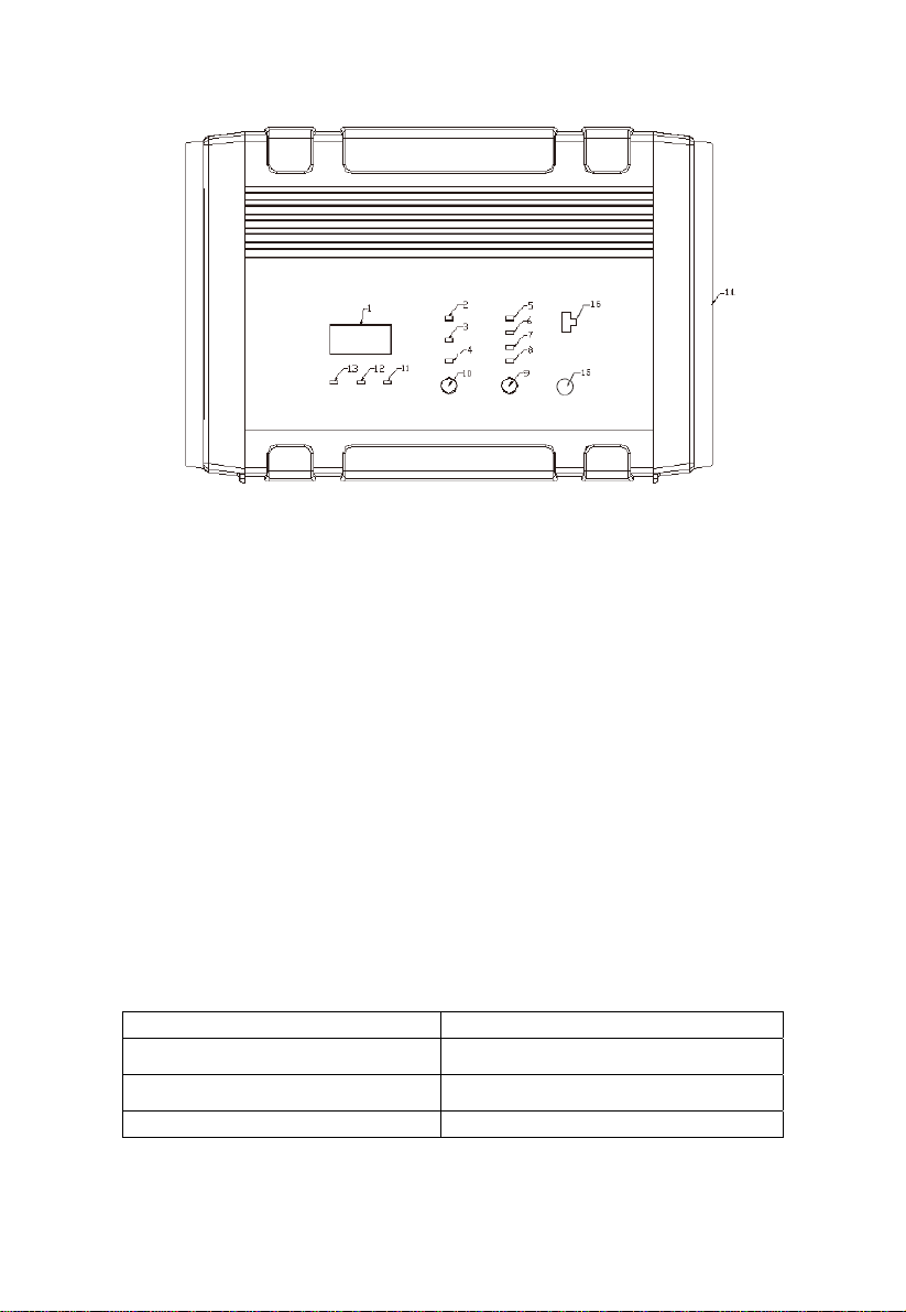
Front panel view
1. Display Panel – Shows present voltage, present current, present
battery capacity or wrong condition code.
With AC power input, when unit is not connected to the battery, the
charger shows that there is no power output with the display panel
present moving “8”. After connected to the battery, the panel will
display the battery information according to what you choose. If the
battery voltage is higher than 13.6±0.2V, the panel will display “FUL”.
When an error occurs, the panel will show a code. Error codes and
solutions are listed in the troubleshooting table.
2. Current Indicator – Green LED indicator. When the display panel
indicates the present current, this LED indicator turns on.
3. Voltage Indicator – Green LED indicator. When the display panel
indicates the present voltage, the voltage LED indicator turns on.
4. Battery level indicator – When the display panel indicates the battery
level, this LED indicator will illuminate.
5. Automatic charging indicator – Indicates the charging rate you
choose is automatic.
Code Condition
LO low Battery
60~90 Current battery level
FUL Full Battery

14
6. 2A current indicator – Indicates the charging rate you choose is 2A.
7. 8A current indicator – Indicates the charging rate you choose is
8A.
8. 12A current indicator – Indicates the charging rate you choose is
12A.
9. Charging rates selecting switch – You can choose the charge
rates-2A, 8A or 12A ,by pressing this switch.
10. Display Button Switch – You can choose what to display on the
panel by pressing the button. The default display is the current
charging rate.
11. Reverse Polarity LED – Red LED. When clips connected the battery
in the wrong way, this red LED illuminates.
12. Battery Recondition Indicator – Yellow LED. When the battery is
reconditioned, this LED flash. The charger will estimate automatically
whether the battery recondition is needed. It will recondition the
battery only when the battery has gone into float charge and the
voltage is lower than 13V. The process cycles every 4±0.5h until the
voltage is higher than 13V. If it cycles 5 times and the voltage is still
lower than 13V, there will be a code “F01” present on the display
panel, indicating error. Please replace the battery.
13. Charging State LED – Green LED. When battery is charged at a
constant current or a constant voltage, the green LED will flash.
When the battery goes into float charge, the charger will cut receiving
power to battery for1 minute to check the charging state. At this time,
the green LED will light up. If the battery tests as full charged or goes
into float charge, the green LED will remain lit.
14. Cooling fan – Built-in high-speed cooling fan. When you charge a
battery in the constant current or constant voltage condition, and the
current is higher than 3.5A,or temperature is more than 122°C (50°F),
the fan will run automatically.
15. Engine start button – Use to jumpstart your vehicle’s battery if it is
low.
16. 2A Maintainer – Use 2A port to do the battery maintenance.

15
Operation for the 2A Maintainer
Connect the extension cord to the charger, and connect the Clamp
cable or Ring cable to the battery, positive (+) to positive (+), negative
(-) to negative (-). Then connect the clamp cable or ring cable to the
extension cord. The red wiring LED will light up if you connect the
cables to the battery incorrectly, and the green LED will light up if you
connected the cables correctly.
NOTE: The digital display will show a moving “8” when the 2Amp
Maintainer cord is in use. Do not use the battery maintainer and the
battery charger simultaneously.
8. USING THE ENGINE START
Your battery charger can be used to jump start your vehicle if the battery
is low.
IMPORTANT: The Engine Start feature cannot be used if a battery is not
installed in the vehicle. The charger must detect some voltage from the
battery or it will not go into Engine Start mode.
1. Make battery and AC connections as outlined in “CHARGING A
BATTERY INSTALLED IN A VEHICLE.”
2. Press the Engine Start button.
Once the Engine Start button is pressed, the charger will begin to
charge the battery at up to 25A until an attempt is made to crank
the engine.
3. Crank the engine for no more than 5 seconds. If the engine does
not start, wait at least 3 minutes before attempting crank again.
Only when actual engine cranking is detected will the charger
then automatically deliver 75A for up to 5 seconds or until the
cranking stops. The digital display will countdown the crank time
in seconds, starting at 555, 444, 333… down to 000.
After 5 seconds of cranking, the charger automatically enters cool
down mode for 3 minutes to protect the charger, battery and
starter from damage. The digital display will begin counting down
in seconds from 180 down to 0. During this time, the charger will
continue to charge the battery at a rate of up to 25A.
4. After the engine starts, unplug the AC cord and disconnect the
cables from the battery.

16
NOTE: A severely discharged battery may not be able to start an
engine even with the assistance of the 75A Engine Start. If your first
few attempts to boost the vehicle are unsuccessful, try charging the
battery at 25A for 20 minutes before attempting to boost again.
9. BATTERY CHARGING TIMES
The built-in intelligent microprocessor will continuously monitor and adjust
the charger to provide a fast, safe and efficient charge. Note that battery
charge times will vary depending on several factors including:
1. Battery State – If a battery has been only slightly discharged, it can
be charged in less than a few hours. This same battery could take
up to 10 hours if very discharged.
2. Battery Rating – A higher rated battery will take longer to charge
than a lower rated battery under the same conditions. A battery is
rated in ampere-hours (Ah), reserve capacity (RC) and cold-cranking
amps (CCA).
3. Charge Rate – The charge rate is measured in amps. A battery
charged at a lower rate will take longer than a battery charged at a
higher rate. However, smaller batteries can be easily damaged by
charging at a rate which is too high for the capacity of the battery.
4. Temperature – Cold temperature will affect a batteries ability to
accept a charge. Charging in cold temperatures will increase the
amount of time required to charge a battery.
Please consult the table to help you to choose the charging rate.
CURRENT SELECTED
TO CHARGE
RECOMMENDED BATTERY CAP.
2A 8AH~20AH
4A 16AH~40AH
12A 48AH~120AH
25A ≥100AH
NOTE: If battery size is unknown, charge at 2A rate. DO NOT
overcharge batteries.

17
10. TROUBLESHOOTING FAULT CODES
Code Condition Possible Cause Solution
F01
Battery voltage is
less than 10 V after
10 minutes of
charging
Short circuit in the
battery.
Go to a professional Lab to
test the battery.
A load may be
connected to the
battery.
Disconnect the load and
attempt to charge again.
Battery voltage is
still less than 13 V
after multiple
reconditioning
attempts
The battery is
sulphated beyond
reconditioning.
Replace the battery.
F02 Charge voltage is
too high
Battery is 24 V, not 12
V.
Confirm that battery is 12
V.
F03 Charge current is
too high
A load may be
connected to the
battery.
Disconnect the load and
attempt to charge again.
F04 Temperature of the
charger is too high
High ambient
temperature.
Ensure adequate
ventilation. The charger
will resume charging after
cooling.
F05
Battery does not go
into Maintenance
mode after being
charged for 24
hours
Charge current is too
low, cannot fully
charge the battery
Select a higher charge
rate.
Short circuit in the
battery. Have the battery checked.
The battery is used
during charging Disconnect the load.
Self-discharging
current is larger than
the floating current
Select a higher charging
rate.
F06 Reverse polarity Battery clamps are
incorrectly connected.
Disconnect clamps and
ensure proper connection.

18
11. MAINTENANCE AND CARE
Clean cords and clamps each time you are finished using the
charger. Wipe off any battery fluid or debris that might have
come in contact with the clamps to prevent corrosion.
Store the power and output cable neatly to prevent damage.
Occasional cleaning of the battery charger case with a soft cloth
will help protect the finish.
Always unplug the charger when not in use.
Keep the charger stored in a cool, dry place.
Table of contents
Other Mäktig Batteries Charger manuals


