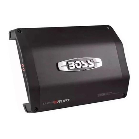
M-PRO MC Series User manual

MC
MC404
M-PRO

The lightning flash with arrowhead symbol within an equilateral triangle is
intended to alert the user to the presence of uninsulated “dangerous”voltage
within the product's enclosure that may be of sufficient magnitude to constitute
a risk of electric shock to humans.
The exclamation point within an equilateral triangle is intended to alert the user
tothe presence of important operating and maintenance (servicing) instructions
in this manual.
The lightning flashes printed next to the output terminals of the amplifier are
intended to alert the user to the risk of hazardous energy. Output connectors
that could pose a risk are marked with the lightning flash. Do not touch output
terminals while amplifier power is on. Make all connections with amplifier
turned off.
CAUTION: TO REDUCE THE RISK OF ELECTRIC SHOCK, DO NOT REMOVE THE
COVER. NO USER-SERVICEABLE PARTS INSIDE. REFER SERVICING TO QUALI-
FIED PERSON NEL.
WARNING: To prevent fire or electric shock, do not expose this equipment to
rain or moisture.
This amplifier hasa serial numberlocated on therear panel.
Please write thisand the modelnumber down andkeep them foryour records.
Keep your purchasereceipt. It isyour proof ofpurchase.
Serial Number:
Date of Purchase:
Purchased From:
Important Safety Precautions & Explanation of Symbols
1
The lightning flash with arrowhead symbol within an equilateral triangle is
intended to alert the user to the presence of uninsulated “dangerous”voltage
within the product's enclosure that may be of sufficient magnitude to constitute
a risk of electric shock to humans.
The exclamation point within an equilateral triangle is intended to alert the user
tothe presence of important operating and maintenance (servicing) instructions
in this manual.
The lightning flashes printed next to the output terminals of the amplifier are
intended to alert the user to the risk of hazardous energy. Output connectors
that could pose a risk are marked with the lightning flash. Do not touch output
terminals while amplifier power is on. Make all connections with amplifier
turned off.
CAUTION: TO REDUCE THE RISK OF ELECTRIC SHOCK, DO NOT REMOVE THE
COVER. NO USER-SERVICEABLE PARTS INSIDE. REFER SERVICING TO QUALI-
FIED PERSON NEL.
WARNING: To prevent fire or electric shock, do not expose this equipment to
rain or moisture.
This amplifier hasa serial numberlocated on therear panel.
Please write thisand the modelnumber down andkeep them foryour records.
Keep your purchasereceipt. It isyour proof ofpurchase.
Serial Number:
Date of Purchase:
Purchased From:

INTRODUCTION
CONTROLS, CONNECTORS & FEATURES
Complementary classAB/H bipolar outputs,with unique floating drive stage for
optimum audio performance.
No dynamic switchingof audio outputs or supply voltages.
Sophisticated monitoring ofload, temperature and operating parameters. Ifove
rheating occurs, thepower supply is reduced to asafe level - protecting the unit
without shut-down.
Low noise vari-speed fans for quiet operation.
Accurate Peak LevelMeters indicating headroom, which automati callyadjust to
power supply andload.These double as level continue rolposition indicators
when adjustments to level are made.
Full DC andshort circuit (serious fault) protection whichauto matically reconnects
when the fault is cleared. Front panel LEDs indicate fault condition.
Modular construction withproprietary heat sinks for ease ofserviceability.
Soft start "power on" sequence with full inrush protection.
1- Unit PowerSwitch
2-Clip Display
3-Signa Displayl
4- Gain Controll
5-Power Display
6-Protection Display
7-XLR input connectors
8-Serial number label
9-speakon output connectors
10-Power cord connector
11-Configuration selector switch
12-Limiter selector switch
13-sensitivity
14-XLR link connectors
11
78910
MC404
1 2 3 4 5 6
M-PRO

SELECTING STEREO, PARALLEL, OR BRIDGE MODE
The amplifier can be set for normal Stereo operation, Parallel input Mode, or
BridgeMono Mode.
Stereo Mode -Each channel remains independent. The amplifier may be used
for two different signals.
Parallel Mode - This setting connects both inputs together. One signal feeds both
channels. Each channel's Gain control and loudspeaker connec tion remain independent.
Bridge Mode - This setting combines both channels into A single channel with twice
the output power. Use only the first channel's input and Gain control.
Do not connect different inputs to each side of a channel pair
when operating in Parallel or Bridge Mode.
.
XLR INPUTS
Each channel has a balanced 3-terminal XLR input. Inputs are
connected with standard cables and can be changed quickly. Pinouts are
marked on the rear panel and shown in the illustration.
The input impedance is 20k ohm balanced or 10k ohm unbalanced.
Balanced connections are recommended to reduce AC hum and interference,
especially with long cable runs. Unbalanced connections may be suitable for
short cables. The signal's source impedance should be less than 600 ohms.
OUTPUTS
Wiring connections are shown on the back of the chassis.
BINDING POST OUTPUTS
Stereo and Parallel Mode: Wire as shown by loudspeaker symbols 1 and 2.
Bridge Mode: Wire as shown by Bridge Mono loudspeaker symbol.
SPEAKON OUPTPUTS
Each channel accepts a normal 2-wire cable. In addition, Channel1accepts
4-wire cables for single cable stereo or (bi-amp)connection.
OUTPUT TERMINAL SAFETY WARNING!
Do nottouch output terminals while amplifier power is on.
Make all connections with amplifier Turned off. Risk of h
azardous energy!
Stereo and Parallel Mode-Connect each loudspeaker to its own
channel of the amplifier, as shown on the left side of the chassis label. The
Mode configuration switches must be set for Stereo or Parallel Mode.
Bridge Mode-Bridge Mode configures the channel pair to drive a single
audio circuit. The Mode configuration switches must be set for Bridge Mode.
Connect the load as shown on the right side of the binding posts or to the
left on Channel 1 s Speakon. 4 ohms is the minimum impedance for
Bridge Mode use.
Do not use less than 4 ohm load in Bridge Mode!
Note polarity of connection for Bridge Mode.
OUTPUT WIRING WARNING:
CLASS 2 WIRING SHALL BE USED. FOR BRIDGED MONO MODE,
CLASS 3 WIRING SHALL BE USED.
.
SIGNAL LINK
Twin maleXLR Connectors fordaisy chaininginput signalto other amplifiers
(parallel connected tofemale input connectors).

GAIN CONTROLS
Turn the Gain controls clockwise to increase Gain and
counterclockwise to decrease Gain.
LED INDICATORS
Displays
The LED displays for each channel operate as follows:
Typical Power Up, Operation, Power Down Behavior
When the amplifier is first turned on, the green POWER displays will light up , and there will
be a 2 secondturn-on delay, during which all red LEDs will be bright (PROTECT and CLIP).
If a channel will not come out of muting, it may be responding to an excessive high frequency
level at the input . Turning down the Gain controls (before you power up the amp is best)
allows the muting to release, and is always a good idea to prevent an unexpected input signal
from overdriving the load.Signal Level will be shown as the green Signal Present, -20dB and
the yellow -10dB display illuminate with increasing signal level .
When the amplifier is turned off, muting should be virtually instantaneous, with all red LEDs
illuminated until the power supply discharges.
CLIP is illuminated at full brightness
when the output is muted
(PROTECT LED is on, too).
If CLIP is illuminated at less than
full LEVEL display, the load is
shorted or abnormal. PROTECT
may flash, too.
CLIP flashing at full LEVEL display
indicates the amp hasreached full
power (clipping) and the limiter is
acting to prevent severe overdrive.
Asteady CLIP glow after the
flashing PROTECT display has
started indicates the onset of
thermal limiting.
PROTECT flashes as the amplifier
approaches max temperature.
Full brightness plus flashing
indicates thermal muting.
Not Illuminated
Full Brightness
Variable or
Occasional Flashing
Flashing
Full Bright
& Flashing
Key to LEDrepresentations:
ON/OFF MUTING
OVERHEATING
SHORTED LOAD
CLIPPING
THERMAL MUTING
LED Displays During
Abnormal Operating Conditions
NO SIGNAL
SIGNAL PRESENT (-25 dB)
SIGNAL PRESENT (-10 dB)
SIGNAL PRESENT (-5 dB)
CLIPPING
LED Displays
During Normal Operation
CLIP Red
ATIVE Green Main power supply active on this channel.
Shows activity of Limiting circuit, which responds
to both clipping and to thermal overload.
Protect Red Flashes as amplifier approaches
maximum temperature.Illuminated steadily plus
flashing during thermal

SPECIFICATIONS
8 Stereo Power 4X400W 4X600W 4X700W
4 Stereo Power 4X600W 4X900W 4X1000W
8 Bridge Power 2X1200W 2X1800W 2X2000W
THD @ Rated Power 4 ohms
1 KHz <0.01%
20Hz - 20KHz <0.03%
Hum&Noise -103dB
Damping Factor 1 kHz, 8 ohms >200 @ 8
Input Sensitivity 1.2V
Input CMRR >80dB
Frequency Response 20Hz 20KHz,+0/-0.5dB
Input Impedance(actively balanced) 20K
amps 25maps amps
Dimensions - 2U X483X4 0
Net Weight 12 13kg 13.5kg
ohms
ohms
ohms
Power Requirement(220VAC) 20
30
88 9
kg
MC404 MC604 MC704
This manual suits for next models
3
Table of contents
