5-2-55, Minamitsumori, Nishinari-ku, Osaka 557-0063 JAPAN
Phone: +81(6)6659-8201 Fax: +81(6)6659-8510 E-mail: info@m-system.co.jp
EM-5656 Rev.21 P. 1 / 6
INSTRUCTION MANUAL
PC RECORDER
(thermocouple or DC input, 16 points) MODEL R1M-GH
BEFORE USE ....
Thank you for choosing M-System. Before use, please check
contents of the package you received as outlined below.
If you have any problems or questions with the product,
please contact M-System’s Sales Office or representatives.
This product is for use in general industrial environments,
therefore may not be suitable for applications which require
higher level of safety (e.g. safety or accident prevention sys-
tems) or of reliability (e.g. vehicle control or combustion con-
trol systems).
For safety, installation and maintenance of this product
must be conducted by qualified personnel.
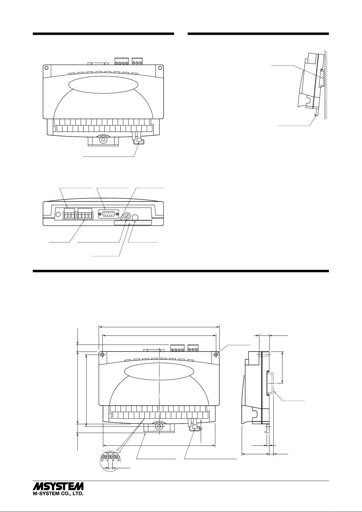
■PACKAGE INCLUDES:
PC Recorder (body + CJC sensor) ......................................(1)
Cable (9-pin D-sub cable, straight type) ............................(1)
CD (software and users manual)........................................(1)
■MODEL NO.
Confirm Model No. marking on the product to be exactly
what you ordered.
■INSTRUCTION MANUAL
This manual describes necessary points of caution when
you use this product, including installation, connection and
basic maintenance procedures. Read also the Users Manual
for the software included in the CD for maximum use of the
PC Recorder.
POINTS OF CAUTION
■CONFORMITY WITH EU DIRECTIVES
• This equipment is suitable for Pollution Degree 2 and
Installation Category II (transient voltage 2500V). Re-
inforced insulation (input or RS-232-C/RS-485 to power:
300V) and basic insulation (input to RS-232-C/RS-485:
300V) are maintained. Prior to installation, check that
the insulation class of this unit satisfies the system re-
quirements.
• Altitude up to 2000 meters.
• The equipment must be mounted inside a panel.
• Insert noise filters. Okaya Electric Industries Model
SUP-E1H or equivalent for the power source connected to
the unit, and TDK Model ZCAT 3035-1330 or equivalent
for the RS-232-C cable are recommended.
• The equipment must be installed such that appropriate
clearance and creepage distances are maintained to con-
form to CE requirements. Failure to observe these re-
quirements may invalidate the CE conformance.
• The actual installation environments such as panel con-
figurations, connected devices, connected wires, may af-
fect the protection level of this unit when it is integrated
in a panel system. The user may have to review the CE
requirements in regard to the whole system and employ
additional protective measures to ensure the CE conform-
ity.
• Install lightning surge protectors for those wires connect-
ed to remote locations.
■POWER INPUT RATING & OPERATIONAL RANGE
• Locate the power input rating marked on the product and
confirm its operational range as indicated below:
100 – 240V AC rating: 85 – 264V, 47 – 66 Hz, approx. 10VA
24V DC rating: 24V ±10%, approx. 7W
■GENERAL PRECAUTIONS
• Before you remove the module, turn off the power supply
and input signal for safety.
■PC RECORDER SOFTWARE
• Use the latest version of PC Recorder Software included
in the product package.
■ENVIRONMENT
• Indoor use.
• When heavy dust or metal particles are present in the air,
install the module inside proper housing with sufficient
ventilation.
• Do not install the module where it is subjected to continu-
ous vibration. Do not subject the unit to physical impact.
• Environmental temperature must be within -5 to +60°C
(23 to 140°F) with relative humidity within 30 to 90% RH
in order to ensure adequate life span and operation.
• Be sure that the ventilation slits are not covered with ca-
bles, etc.
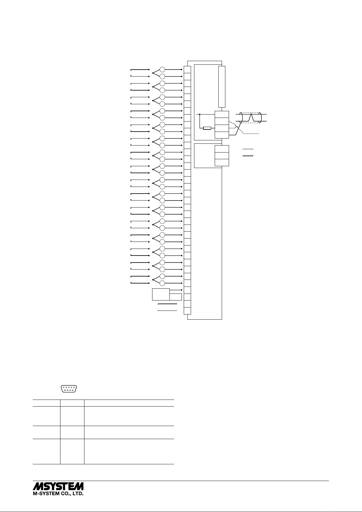
■WIRING
• Wrong connection may damage the module.
• Do not connect cables to moving parts or pull them tightly.
• Do not install cables close to noise sources (relay drive
cable, high frequency line, etc.).
• Do not bind these cables together with those in which
noises are present. Do not install them in the same duct.
■AND ....
• The module is designed to function as soon as power is
supplied, however, a warm up for 10 minutes is required
for satisfying complete performance described in the data
sheet.