M-TI 91743 User manual

MTI DOC 91743-A1
MTI Digital Intercom Amplifier
Part Number 91743
Simple, Reliable
and Cost Effective
Technology
I N S T A L L A T I O N

MTI DOC 91743-A1
TABLE OF CONTENTS
DESCRIPTION...…………………………………………………………………….... 1
PRODUCT OVERVIEW..………………………………………………………………. 3
CONNECTING TO THE NETWORK…….....…………………………………… 4
CONNECTING POWER……….....……………………………………………. 4
CONNECTING THE SPEAKER BUSS………………………………….………. 4
CONNECTING A PAGE AMPLIFIER………….……………………………….. 5
BEFORE YOU BEGIN………….……………………………………………………… 6
PARTS LIST…………………………………………………………………. 6
PRODUCT SERIAL NUMBER LABEL PLACEMENT….………………………… 6
INSTALLATION………………………………………………………………………. 7
START UP………………….………………………………………………… 7
SPECIFICATIONS...…………………………………………………………………... 8
FEATURES…….....…………………………………………………………………... 9
APPENDIX…….....………………………………………………………………….... 11

MTI DOC 91743-A1
DESCRIPTION
The MTI 91743 Digital Amplifier is a cost effective solution for intercom applications. The 91743
communicates with the intercom master (i.e. touch screen computer or handheld device) over a
standard Ethernet connection. The amplifier is designed to connect to a 25V intercom system. The
digital amplifier also supports up to a 60W paging amplifier interface. In the standard MTI
Intercom system, the 91743 connects to the MTI Intercom termination boards (81129/81229) via
the speaker buss. See Figure 3 for the typical hookup for the 91743 digital amplifier.
The 91743 Digital Amplifier has two LED indications on the front panel. After the boot sequence,
the green LED will flash every second. When the amp is in talk mode, the red LED will be solid
on. The red LED will flash every second when in page mode.
Primary volume adjustment can be achieved remotely using MTI ProVision software. If additional
receive volume adjustment is needed, the potentiometer on the front panel can be used.
ELO
DATACONVERTER
+12V
COM
D1
D2
CLK
CHAN1
+12V
COM
D1
D2
CLK
CHAN4
CHAN5
CLK
D2
D1
COM
+12V
CHAN8
CLK
D2
D1
COM
+12V
+12V
COM
HGND
NETWORK
+12V
COM
D1
D2
CLK
CHAN3
CLK
D2
D1
COM
+12V
CHAN7
+12V
COM
D1
D2
CLK
CHAN2
CLK
D2
D1
COM
+12V
CHAN6
MTIPN
91620
COM
PWR
HGND
LED
A-X5
A-X6
A-X7
A-X6
On/Off
Day/Ngt
AUD1
AUD1
AUD2
AUD2
SHLD
SHLD
CALL
COM
7
MTI PN
51129B
D2
CLK
COM
D1
+12
6 5 4 23 1 0 7 6 5 4 3 2 1 0
MTIPART NO.
51222
D1
D2
C
COM
+12
+24
COM
COM
24COM
MTIPN 51155A
EMBEDDED CONTROLLER
NETWORK
MTIPN 9169 5-1
V
I
N
C
O
M
LED
ON PORT
COM
Figure 1: Sample MTI control system
1

MTI DOC 91743-A1
Figure 2: Typical MTI Intercom System Diagram
2
MTI Touch
Screen
MTI Handheld
Network
91743
Digital
Amplifier
Page
Out
Page
In
Paging Amplifier
8
1
1
2
9
8
1
1
2
9
9
SPK Buss
25V
Line

MTI DOC 91743-A1
PRODUCT OVERVIEW
Figure 3: 91743 Digital Intercom Amplifier Connections
3

MTI DOC 91743-A1
CONNECTING TO THE NETWORK
The 91743 Digital Intercom Amplifier supports a 100 Mbps network connection.
1. Connect a Cat5e (or better) unshielded twisted pair (UTP) cable and connector to the RJ-
45 connector on the 91743.
2. Connect the other end of the UTP cable to an available port on a 10/100 (minimum)
compatible network switch.
CONNECTING POWER
The 91743 Digital Intercom Amplifier requires a connection to a 12V DC power supply which is
capable of supplying 2 A of current.
To connect power:
1. Connect two power conductors to pin 1 and 2 of the power connector.
2. Connect the other end of the two power conductors to the appropriate power source.
The 91743 ships with a 12V DC power supply which already has the five position connector pre-
terminated.
CONNECTING THE SPEAKER BUSS
The 91743 Digital Intercom Amplifier is intended to be used with MTI 81129/229 termination
boards and 25 volt line audio devices. The speaker buss from the amplifier connects to the
termination boards which distribute the audio signal to the audio devices. MTI recommends
using West Penn Wire #292 cable for connecting an amplifier to MTI termination boards.
To connect the speaker buss to an MTI 81129/229 termination board:
1. Connect one end of the WPW 292 cable to the speaker buss connector on the MTI
termination boards.
2. Connect the other end of the WPW 292 cable to the speaker buss connector on the MTI
91743 amplifier.
4

MTI DOC 91743-A1
CONNECTING A PAGE AMPLIFIER
When used in conjunction with a paging amplifier, the 91743 Digital Intercom Amplifier
supports paging over the intercom system. The maximum required power that can be sourced to
each paging zone is 60W. The “Page In” signal on the 91743 is an unbalanced microphone level
output which can be connected to the input of an external paging amplifier. The input of the
paging amplifier must be unbalanced. The “Page Out” signal on the 91743 should be connected
to the output of the paging amplifier. When the amplifier is in page mode, the output of the
paging amplifier is directly connected to the MTI speaker buss. This allows 25 or 70 volt paging
speakers to be used depending on the output of the paging amplifier. Typical page amplifier
hookups can be seen in the Appendix.
To connect a MTI 91743 to a paging amplifier:
1. Connect two appropriately sized conductors to the “Page In” signals on the 91743.
2. Connect the other end of the conductors to an unbalanced, microphone level input of the
paging amplifier.
3. Connect two appropriately sized conductors to the “Page Out” signals on the 91743.
4. Connect the other end of the conductors to the output of the paging amplifier.
5

MTI DOC 91743-A1
BEFORE YOU BEGIN
You will also need the following:
An installed MTI Intercom System including 81129/229 termination boards and audio
devices.
Hand tools and din rail to mount the 91743 in the cabinet/rack
PARTS LIST
Qty Description
1MTI 91743 Digital Intercom Amplifier
112V DC Power Supply
191743 Installation Manual (MTI DOC 91743-A1)
1Product Serial Number Label (attached to the bottom of the 91743 case)
PRODUCT SERIAL NUMBER LABEL PLACEMENT
The product serial number label helps identify your 91743 Digital Intercom Amplifier in the
event that your 91743 requires service. The serial number label is located on the bottom of the
91743.
6

MTI DOC 91743-A1
INSTALLATION
The 91743 Digital Intercom Amplifier can be din rail mounted to any back plate in a cabinet or
rack. The 91743 must be mounted so that the ventilation holes are aligned vertically to allow air
to flow properly.
To install the 91743 to a back plate:
1. Install the din rail on the back plate.
2. Mount the 91743 on the din rail.
STARTUP
To start the 91743 Digital Intercom Amplifier:
1. Make all required connections as discussed in the Product Overview section.
2. Turn on the intercom system and verify the proper operation of the 81129/229
termination boards.
3. Turn on the MTI intercom amplifier and associated intercom master station.
7

MTI DOC 91743-A1
SPECIFICATIONS
Auxiliary Interfaces
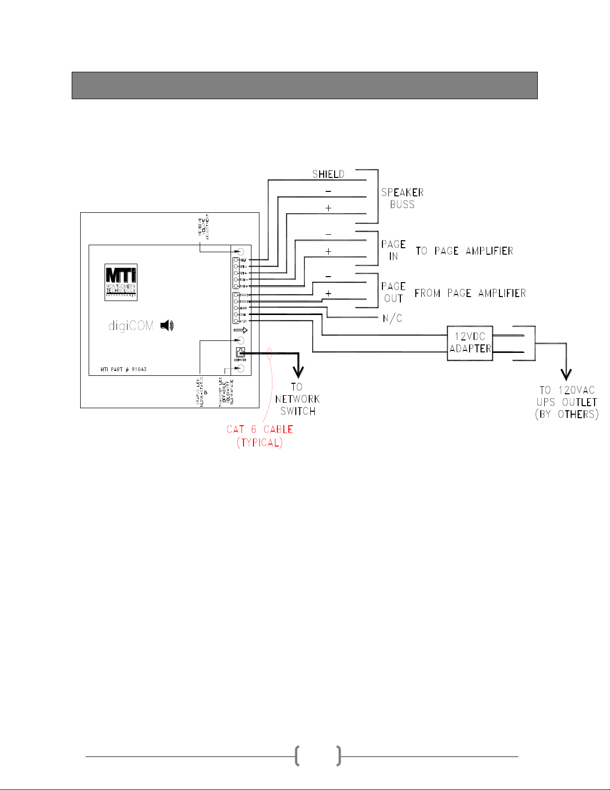
Power/Audio Ports Two –five position connectors
Power
Power Supply Voltage 12V DC (+/- 10%)
Power Supply Current (max) 2A
Audio
Speaker Buss Interface 25V Line
Max Output Power (talk mode) 2W
Max Paging Power (page mode) 60W (requires external paging amplifier)
Total Harmonic Distortion <1%
Frequency Range 100 Hz to 12 kHz
Sample Rate 8 kHz
Sample Resolution 8 or 16 bit
Network
Interface 10/100 Ethernet RJ-45 port (100Base-T)
LED Indications
Run Mode Green (blinks on and off once a second)
Audio Transmit –Talk Mode Red (solid on)
Audio Transmit –Page Mode Red (blinks on and off once a second)
Network Activity Green
Network Status Amber
Network
Interface 10/100 Ethernet RJ-45 port (100Base-T)
Environmental
Operating Temperature 32⁰to 120⁰F
Storage Temperature -40⁰to 149⁰F
Operating Humidity 20% to 85%, noncondensing
Maximum Humidity Gradient 10% per hour
Operating Altitude -50 to 10,000 ft
Physical
Construction UL94V-O Flame Retardant ABS
Finish Black
Dimensions 6”Lx5.25”W
Mounting Din Rail
Unit Weight 1.15 lbs

MTI DOC 91743-A1
FEATURES
The 91743 digital amplifier provides all of the standard features of any IP-based intercom
system. These features include, but are not limited to the following set:
1. TCP/IP based digital transmission of all audio communications between master stations
(touchscreen computers) and the amplifier via g.711 digital audio encoding.
2. A single digital amplifier, along with use of MTI 81129 or 81229 termination boards, can
support any number of intercom stations.
3. The system can be utilized to meet any number of configuration requirements. The
standard configuration method is to utilize 81129/229 intercom termination boards for
switching the analog input/output between the digital amplifier and a set of intercom staff
stations. If desired, the digital amplifier can be used in a 1:1 configuration, in which one
digital amplifier directly connects to a single staff station, providing a fully digital system
to the staff station.
4. Communications to and from the 91743 can be managed through a standard Microsoft
Windows-based computer with PC sound card, or via a separate handset master station
connected through the computer.
5. The mounting hardware provided with the 91743 and supporting components allows for
simple installation under most configurations, including cabinet or rack mounting (with
use of a backplate).
6. With the use of the MTI ProDesign suite, stations can be assigned labels based on an
alpha-numeric numbering system. This allows the designer to assign station
names/numbers based on a numbering system or a text-based naming system.
7. With the use of the MTI ProVision application, the intercom system can provide master-
to-master calling and/or master-to-station calling.
8. Call indication can be activated through a number of inputs, including:
a. Call station push button
b. Auxiliary input such as a card access system or other indication.
c. Audio Level (Scream alarm).
9. Call management can be governed by standard Push-To-Talk (PTT) control via the
ProVision application, or through VOX still “ambient noise” control. For detention
facilities, MTI recommends the use of the PTT feature so that the operator has full
control over the flow of the conversation.
10. With the use of the ProVision application, the operator has the option to “protect” any
intercom. Through this feature, the operator can enter a sort of “privacy” mode, in which
the operator will only receive call-ins that are tagged as alarm points (such as audio level
alerts).
11. The intercom system can be programmed to handle any number of paging zones,
depending on the intercom system configuration.
12. The system can provide group paging capabilities, in which a single group page can be
initiated from any associated master station.
13. Multiple paging zones can be activated through an “All-Call” button, or through a group
paging icon.

MTI DOC 91743-A1
14. Utilizing the PLC logic, any number of behaviors can be added to the intercom system,
such as emergency intercom shutdown, emergency all-call, pre-recorded notifications,
and so on.
15. Individual staff stations can be included in a paging zone so that the operator can page
individual cells.
16. Auxiliary input can be provided through the paging system to allow for audio from a
secondary source, for use in situations where music or other audio is desired.
17. The intercom system provides a number of call handling features, such as the following:
a. Single-touch dialing via the use of on-screen icons.
b. Call forwarding –Master stations can be configured in a “call-stack”, in which
certain stations receive a priority level. Intercom call-ins will flow through the
stack based on the priority given each station. If stations at first priority do not
answer within a designated time period, the second level priority stations will
receive the call. Multiple stations can be given the same priority levels so that any
station at the same level can answer the call.
c. The system can be configured to annunciate a call-in through a continuous calling
tone.
d. The operator can be provided the option of handling calls via the computer’s
standard sound card, or via a handset option.
e. The system can be configured to allow any master station control over any
intercom, or to refuse control of any call station or paging zone to any master
station. Furthermore, through the use of operator security levels, access to
individual call stations can be allowed or denied based on the operator’s
permissions. Also, call station access can be managed through the task-group
feature of the ProVision application, in which operators only see and have access
to the call stations included within their associated task group.
f. Group remote response capabilities.
g. Passive station monitoring is available, in which a master station can be set to
cycle through an arbitrary arrangement of staff stations for passive supervision
purposes.
h. Master override capabilities are available, in which a higher-priority station can
override a lower priority station’s conversation.
i. Call-in time-outs can be set so that any call-in will automatically end after a
prescribed time.
j. Auxiliary activation of intercom calls can be accommodated through dry contact
inputs. In this case, a separate physical input can initiate a predefined call, such as
a paging station or direct staff station call.
18. The intercom system can be configured to provide interfaces to auxiliary systems, such as
CCTV systems, for added functionality. These interfaces can be provided via dry contact,
serial communications, or (in some cases) direct API interface.

MTI DOC 91743-A1
APPENDIX
PGIN -
Aux -
Aux +
25V
COM
AT-340
91743
Digital
Amp
PGIN +
PGOUT +
PGOUT -
Figure 5: Typical Hookup for Line Level Page Amplifier Inputs
PGIN -
PGIN +
91743
Digital
Amp
PGOUT -
PGOUT +
Input GND
Input -
Input +
Output B +
Output B -
Line In +
Line In -
COM
Page
Amp
Radio Design Labs
STM-2
25V
Figure 4: Typical Hookup to a Burtek AT-340 Paging Amplifier
8
11
Table of contents
Other M-TI Amplifier manuals