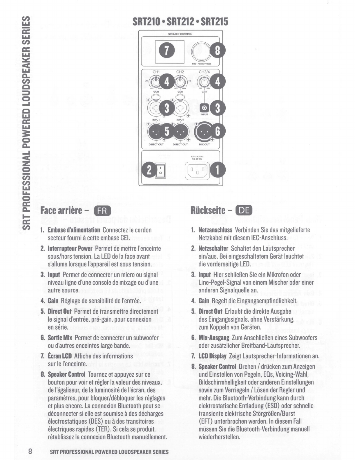
Mackie SRT21D User manual

SRT
PROFESSIONAL POWERED LOUDSPEAKER
SERIES
QUICK
START
GUIDE
SRT21D
SRT212
SRT215

Cl)
LI.I
c2
LI.I
Cl)
cc:
LI.I
:=.::
cc
LI.I
CL.
Cl)
Q
::::::,
C)
....I
Q
LI.I
cc:
LI.I
==
C)
CL.
....I
cc
z
C)
-
Cl)
Cl)
LI.I
LI.
C)
cc:
CL.
t-
ee:
Cl)
Important
Safety
Instructions
-D
1.
Read
these
instructions.
2.
Keep
these
instructions.
3.
Heed
all
warnings.
4.
Follow
all
instructions.
5.
Do
not
use
this
apparatus
near
water.
6.
Clean
only
with
a
dry
cloth.
7.
Do
not
block
any
ventilation
openings.
Install
in
accordance
with
the
manufacturer's
instructions.
8.
Minimum
distance
(5
cm)
around
the
apparatus
for
sufficient
ventilation.
The
ventilation
should
not
be
impeded
by
covering
the
ventilation
openings
with
items,
such
as
newspapers,
table-cloths,
curtains,
etc.
9.
Do
not
install
near
any
heat
sources
such
as
radiators,
heat
registers,
stoves,
or
other
apparatus
(including
amplifiers)
that
produce
heat.
10.No
naked
flame
sources,
such
as
lighted
candles,
should
be
placed
on
the
apparatus.
11.
Do
not
defeat
the
safety
purpose
of
the
polarized
or
grounding-type
plug.
A
polarized
plug
has
two
blades
with
one
wider
than
the
other.
A
grounding-type
plug
has
two
blades
and
a
third
grounding
prong.
The
wide
blade
or
the
third
prong
are
provided
for
your
safety.
If
the
provided
plug
does
not
fit
into
your
outlet,
consult
an
electrician
for
replacement
of
the
obsolete
outlet.
12.Protect
the
power
cord
from
being
walked
on
or
pinched
particularly
at
plugs,
convenience
receptacles,
and
the
point
where
they
exit
from
the
apparatus.
13.0nly
use
attachments/accessories
specified
by
the
manufacturer
.
14.Use
only
with
a
cart,
stand,
tripod,
bracket,
or
table
specified
by
the
manufacturer,
or
sold
with
the
apparatus
.
When
a
cart
is
used,
use
caution
when
moving
the
cart/
apparatus
combination
to
avoid
injury
from
tip-over.
15.Unplug
this
apparatus
during
lightning
storms
or
when
unused
for
long
periods
of
time.
16.Refer
all
servicing
to
qualified
service
personnel.
Servicing
is
required
when
the
apparatus
has
been
damaged
in
any
PORTABLE
CART
WARNING
(I
way,
such
as
power-supply
cord
or
plug
is
damaged,
liquid
has
been
spilled
or
objects
have
fallen
into
the
apparatus,
the
apparatus
has
been
exposed
to
rain
or
moisture,
does
not
operate
normally,
or
has
been
dropped.
17.
This
apparatus
shall
not
be
exposed
to
dripping
or
splashing,
and
no
object
filled
with
liquids,
such
as
vases
or
beer
glasses,
shall
be
placed
on
the
apparatus.
18.
Do
not
overload
wall
outlets
and
extension
cords
as
this
can
result
in
a
risk
of
fire
or
electric
shock.
CAUTION
RISK
OF
ELECTRIC
SHOCK!
DO
NOT
OPEN!
Lh
CAUTION:
TO
REDUCE
THE
RISK
OF
ELECTRIC
SHOCK
00
NOT
REMOVE
COVER
(OR
BACK).
NO
USER-SERVICEABLE
PARTS
INSIDE
.
REFER
SERVICING
TO
QUALIFIED
PERSONNEL.
The
lightning
flash
with
arrowhead
symbol
within
an
equilateral
triangle
is
intended
to
alert
the
user
to
the
prescence
of
uninsulated
"dangerous
voltage"
within
the
product's
enclosure,
that
may
be
of
significant
magnitude
to
constitute
a
risk
of
electric
shock
to
persons.
The
exclamation
point
within
an
equilateral
triangle
is
intended
to
alert
the
user
of
the
prescence
of
important
operating
and
maintaining
(servicing)
instructions
in
the
literature
accompanying
the
appliance.
19.
@_I
This
apparatus
has
been
designed
with
Class-I
construction
and
must
be
connected
to
a
mains
socket
outlet
with
a
protective
earthing
connection
(the
third
grounding
prong).
20.
This
apparatus
has
been
equipped
with
a
rocker-style
AC
mains
power
switch
.
This
switch
is
located
on
the
rear
panel
and
should
remain
readily
accessible
to
the
user
.
21.
The
MAINS
plug
or
an
appliance
coupler
is
used
as
the
disconnect
device,
so
the
disconnect
device
shall
remain
readily
operable.
WARNING
-
To
reduce
the
risk
of
fire
or
electric
shock,
do
not
expose
this
apparatus
to
rain
or
moisture.
CAUTION
-
To
prevent
electric
shock
hazard,
do
not
connect
to
mains
power
supply
while
grille
is
removed.
22.
The
use
of
apparatus
is
in
moderate
climates.
23.
This
device
should
be
installed
and
operated
with
minimum
distance
20cm
between
the
radiator
&
your
body
.
The
product
can
be
sold
in
all
EU
countries.
Bluetooth
transmitter
Power:
s19dBm
Bluetooth
transmitter
frequency
range:
2.402
-
2.480
GHz
24.
NOTE:
This
equipment
has
been
tested
and
found
to
comply
with
the
limits
for
a
Class
A
digital
device,
pursuant
to
part
15
of
the
FCC
Rules.
These
limits
are
designed
to
provide
reasonable
protection
against
harmful
interference
when
the
equipment
is
operated
in
a
commercial
environment.
This
equipment
generates,
uses,
and
can
radiate
radio
frequency
energy
and,
if
not
installed
and
used
in
accordance
with
the
instruction
manual,
may
cause
harmful
interference
to
radio
communications.
Operation
of
this
equipment
in
a
residential
area
is
likely
to
cause
harmful
interference
in
which
case
the
user
will
be
required
to
correct
the
interference
at
his
own
expense.
NOTE:
Equipment
meeting
Class
A
requirements
may
not
offer
adequate
protection
to
broadcast
services
within
a
residential
environment.
CAUTION:
Changes
or
modifications
to
this
device
not
expressly
approved
by
LOUD
Audio,
LLC
could
void
the
user's
authority
to
operate
the
equipment
under
FCC
rules.
25.
This
apparatus
does
not
exceed
the
Class
A/Class
B
(whichever
is
applicable)
limits
for
radio
noise
emissions
from
digital
apparatus
as
set
out
in
the
radio
interference
regulations
of
the
Canadian
Department
of
Communications.
Canada
ICES-003(A)/NMB-003(A)
ATTENTION
-
Le
present
appareil
numerique
n'emet
pas
de
bruits
radioelectriques
depassant
las
limites
app!icables
aux
appareils
numeriques
de
class
A/de
class
B
(selon
le
cas)
prescrites
dans
le
reglement
sur
le
brouillage
radioelectrique
edicte
par
!es
ministere
des
communications
du
Canada.
26.
Exposure
to
extremely
high
noise
levels
may
cause
permanent
hearing
loss.
Individuals
vary
considerably
in
susceptibility
to
noise-induced
hearing
loss,
but
nearly
everyone
will
lose
some
hearing
if
exposed
to
sufficiently
intense
noise
for
a
period
of
time.
The
U.S.
Government's
Occupational
Safety
and
Health
Administration
(OSHA)
has
specified
the
permissible
noise
level
exposures
shown
in
the
following
chart.
According
to
OSHA
,
any
exposure
in
excess
of
these
permissible
limits
could
result
in
some
hearing
loss.
To
ensure
against
potentially
dangerous
exposure
to
high
sound
pressure
levels,
it
is
recommended
that
all
persons
exposed
to
equipment
capable
of
producing
high
sound
pressure
levels
use
hearing
protectors
while
the
equipment
is
in
operation.
Ear
plugs
or
protectors
in
the
ear
canals
or
over
the
ears
must
be
worn
when
operating
the
equipment
in
order
to
prevent
permanent
hearing
loss
if
exposure
is
in
excess
of
the
limits
set
forth
here:
Duration
,
per
Sound
Level
dBA,
Typical
Example
day
in
hours
Slow
Response
8
90
Duo
in
small
club
6
92
4
95
Subwav
Train
3
97
2
100
Verv
loud
classical
music
1.5
102
1
105
Matt
screaming
at
Trov
about
deadlines
0.5
110
0.25
or
less
115
Loudest
oarts
at
a
rock
concert
Laite
on
liitettiivii
suojakoskettimilla
varustettuun
pistorasiaan.
Apparatet
stikprop
skal
tilsluttes
en
stikkontakt
med
·ord,
som
iver
forbindelse
til
stik
ro
ens
·ord.
I
Apparatet
ma
tilkoples
jordet
stikkontakt.
I
I
Apparaten
skall
anslutas
till
jordat
uttag.
I
Correct
disposal
of
this
product:
This
symbol
indicates
thatthis
product
should
not
be
disposed
of
with
your
household
waste,
according
to
the
WEEE
directive
(2012/19/EU)
and
~our
national
law.
This
product
should
be
ha_nded
over
to
an
authorized
collection
site
for
recycling
waste
electrical
and
electronic
equipment
(EEE).
Improper
handling
of
this
type
of
waste
could
have
a
possible
negative
impact
on
the
environment
and
human
health
due
to
potentially
hazardous
substances
that
are
generally
associated
with
EEE.
At
the
same
time,
your
cooperation
in
the
correct
disposal
of
this
product
will
contribute
to
the
effective
usage
of
natural
resources.
For
more
information
about
where
-
you
can
drop
off
your
waste
equipment
for
recycling,
please
contact
your
local
city
office
,
waste
authority,
or
your
household
waste
disposal
service.
2
SRT
PROFESSIONAL
POWERED
LOUDSPEAKER
SERIES

(I)
LI.I
a:
LI.I
(I)
a:
LI.I
:::i.::
c:c
LI.I
a.
(I)
Q
::::::,
C)
....I
C
LI.I
a:
LI.I
==
C)
a.
....I
c:c
z
C)
-
(I)
(I)
LI.I
LI.
C)
a:
a.
t-
a:
(I)
Hookup
Diagrams
•
Diagramas
de
conexion
Schemas
de
ciblage
•
Anschlussdiagrammes
Stereo
Speaker
Hookup
Conexion
de
altavoz
stereo
Connexion
en
stereo
Stereo
Setup
-i--~)-
ij
...+-----------Ill!!!
~· - ).1 i
~
•••
-i--i-
ij
'---------al!!!
!!!!cJ
+
-)
+ i
~
•••
PA
System
with
one
powered
subwoofer
Sistema
PA
con
un
subwoofer
autoamplificado
Systeme
de
sonorisation
avec
un
Subwoofer
actif
PA-System
mit
einem
aktiven
Subwoofer
6
SRT
PROFESSIONAL
POWERED
LOUDSPEAKER
SERIES
Using
a
microphone
and
daisy-chaining
Uso
de
un
microfono
y
conexi6n
en
cadena
Utilisation
d'un
micro
et
connexion
en
cascade
Verwendung
eines
Mikrofons
mit
Boxen
in
Relhenschaltung
DRM18S
PA
System
with
two
powered
subwoofers
Sistema
PA
con
dos
subwoofers
autoamplificados
Systeme
de
sonorisation
avec
deux
Subwoofers
actifs
PA-System
mit
zwei
aktiven
Subwoofern

SRT210
•
SRT212
•
SRT215
SPEAKER
CONTROL
---
~
~
INPUT INPUT
---
®
DIRECT
OUT
DIRECT
OUT
Rear
Panel
Descriptions
-
OD
1.
Power
Connector
Connect
the
supplied
AC
power
cord
to
this
IEC
jack.
2.
Power
Switch
Turns
the
loudspeaker
on
and
off.
The
front
LED
will
illuminate
when
powered.
3.
Input
Connect
a
mic
or
line-level
signal
from
a
mixer
or
other
signal
source.
4.
Gain
Adjusts
the
input
sensitivity.
5.
Direct
Out
Allows
for
a
direct
output
of
the
input
signal,
pre-gain,
for
daisy
chain
purposes.
6.
Mix
Out
Connect
subwoofer
or
additional
full
range
loudspeakers.
7.
LCD
Display
Displays
the
loudspeaker
information.
8.
Speaker
Control
Rotate
/
push
to
see
and
adjust
levels,
EO,
select
voicing,
screen
brightness,
settings
and
to
lock/
unlock
the
controls
and
more.
The
Bluetooth
connection
may
disconnect
when
affected
by
electrostatic
discharge
(ESD)
or
electrical
fast
transients
(EFT).
If
this
occurs,
manually
reconnect
the
Bluetooth
connection.
100-240VAC
50
-
60Hz
Descripcion
del
panel
trasero
-1B
1.
Toma
de
corriente
Conecte
en
esta
toma
IEC
el
cable
de
alimentaci6n
incluido.
2.
lnterruptor
Power
Le
permite
encender
y
apagar
el
recinto
acustico.
El
piloto
frontal
se
iluminara
cuando
la
unidad
este
encendida.
3.
Input
Conecte
una
serial
de
nivel
de
micro
o
If
nea
procedente
de
un
mezclador
u
otra
fuente
de
serial.
4.
Gain
Ajusta
la
sensibilidad
de
entrada.
5.
Direct
Out
Permite
la
emisi6n
directa
de
la
serial
de
entrada,
pre-ganancia,
para
cuando
la
vaya
a
usar
en
conexiones
en
cadena.
6.
Mix
Out
Conecte
aqu1
el
subwoofer
o
recintos
acusticos
de
rango
completo
adicionales.
7.
Pantalla
LCD
Le
muestra
la
informaci6n
del
altavoz.
8.
Speaker
Control
Gire/pulse
para
visualizar
y
ajustar
niveles,
EO,
elegir
distintos
voicing,
brillo
de
la
pantalla,
ajustes
y
para
bloquear/desbloquear
los
controles
y
mas.
En
enlace
Bluetooth
puede
desconectarse
si
se
ve
afectado
por
una
descarga
de
electrostatica
(ESD)
o
transitorios
electricos
bruscos
(EFT).
En
esos
casos,
reconecte
manualmente
el
enlace
Bluetooth.
C)
C
-·
n
~
Cl)
....
~
-s
....
C,
C
-·
a.
m
Quick
Start
Guide
7

(I)
LI.I
SRT210
•
SRT212
•
SRT215
c2
LI.I
(I)
cc:
LI.I
::.:::
cc
LI.I
c..
(I)
Cl
::::,
C)
....I
Cl
LI.I
cc:
LI.I
3:
C)
c..
....I
cc
z
C)
-
(I)
(I)
LI.I
L&.
C)
cc:
c..
Face
arriere
-
Iii
Ii:
en
1.
Embase
d'alimentation
Connectez
le
cordon
secteur
fourni
a
cette
embase
CEI.
2.
lnterrupteur
Power
Permet
de
mettre
l'enceinte
sous/hors
tension.
La
LED
de
la
face
avant
s'allume
lorsque
l'appareil
est
sous
tension.
3.
Input
Permet
de
connecter
un
micro
ou
signal
niveau
ligne
d'une
console
de
mixage
ou
d'une
autre
source.
4.
Gain
Reglage
de
sensibilite
de
l'entree.
5.
Direct
Out
Permet
de
transmettre
directement
le
signal
d'entree,
pre-gain,
pour
connexion
en
serie.
6.
Sortie
Mix
Permet
de
connecter
un
subwoofer
ou
d'autres
enceintes
large
bande.
7.
Ecran
LCD
Affiche
des
informations
sur
le
l'enceinte.
8.
Speaker
Control
Tournez
et
appuyez
sur
ce
bouton
pour
voir
et
regler
la
valeur
des
niveaux,
de
l'egaliseur,
de
la
luminosite
de
l'ecran,
des
parametres,
pour
bloquer/debloquer
les
reglages
et
plus
encore.
La
connexion
Bluetooth
peut
se
deconnecter
si
elle
est
soumise
a
des
decharges
electrostatiques
(DES)
ou
a
des
transitoires
electriques
rapid
es
(TER).
Si
cela
se
produit,
retablissez
la
connexion
Bluetooth
manuellement.
SPEAKER CONTROL
Riickseite
-B
1.
Netzanschluss
Verbinden
Sie
das
mitgelieferte
Netzkabel
mit
diesem
IEC-Anschluss.
2.
Netzschalter
Schaltet
den
Lautsprecher
ein/aus.
Bei
eingeschaltetem
Gerat
leuchtet
die
vorderseitige
LED.
3.
Input
Hier
schlieBen
Sie
ein
Mikrofon
oder
Line-Pegel-Signal
von
einem
Mischer
oder
einer
anderen
Signalquelle
an.
4.
Gain
Regelt
die
Eingangsempfindlichkeit.
5.
Direct
Out
Erlaubt
die
direkte
Ausgabe
des
Eingangssignals,
ohne
Verstarkung,
zum
Koppeln
von
Geraten.
6.
Mix-Ausgang
Zurn
AnschlieBen
eines
Subwoofers
oder
zusatzlicher
Breitband-Lautsprecher.
7.
LCD
Display
Zeigt
Lautsprecher-lnformationen
an.
8.
Speaker
Control
Drehen
/
drucken
zum
Anzeigen
und
Einstellen
von
Pegeln,
EQs,
Voicing-Wahl,
Bildschirmhelligkeit
oder
anderen
Einstellungen
sowie
zum
Verriegeln
/
Ltisen
der
Regler
und
mehr.
Die
Bluetooth-Verbindung
kann
durch
elektrostatische
Entladung
(ESD)
oder
schnelle
transiente
elektrische
SttirgrtiBen/Burst
(EFT)
unterbrochen
werden.
In
diesem
Fall
mussen
Sie
die
Bluetooth-Verbindung
manuell
wiederherstellen.
8
SRT
PROFESSIONAL
POWERED
LOUDSPEAKER
SERIES

Getting
Started
-
OD
1.
Read
and
understand
the
Important
Safety
Instructions
on
page
2.
2.
Make
all
initial
connections
with
the
power
switches
OFF
on
all
equipment.
Make
sure
the
master
volume,
level
and
gain
controls
are
all
the
way
down.
3.
If
not
using
a
subwoofer,
connect
the
outputs
from
the
mixing
console
(or
other
signal
source)
to
the
inputs
on
the
rear
panel
of
the
loudspeakers.
4.
If
using
a
subwoofer,
connect
the
outputs
from
the
mixing
console
(or
other
signal
source)
to
the
inputs
on
the
rear
panel
of
the
subwoofer,
then
connect
the
high
pass
outputs
from
the
subwoofer
to
the
inputs
of
the
loudspeakers.
5.
Push
the
line
cord
securely
into
the
subwoofer's/
loudspeaker's
IEC
connectors
and
plug
the
other
ends
into
grounded
AC
outlets.
The
subwoofer/loudspeaker
may
accept
the
appropriate
voltage
as
indicated
near
the
IEC
connector.
6.
Turn
the
mixer
(or
other
signal
source)
on.
7.
Turn
the
subwoofer
on.
8.
Turn
the
loudspeakers
on.
9.
Be
sure
that
the
volume
of
the
input
is
the
same
as
it
would
be
during
normal
use.
10.
Start
the
signal
source
and
raise
the
mixer's
main
L/R
fader
up
to
a
comfortably
loud
listening
level.
Puesta
en
marcha
-8
1.
Lea
y
tenga
en
cuenta
las
lnstrucciones
importantes
de
seguridad
de
la
pagina
3.
2.
Realice
todas
las
conexiones
iniciales
con
todos
los
aparatos
APAGADOS.
Asegurese
de
que
los
controles
de
volumen
master,
nivel
y
ganancia
esten
al
mfnimo.
3.
Si
no
esta
usando
un
subwoofer,
conecte
las
salidas
de
la
mesa
de
mezclas
(u
otra
fuente
de
serial)
a
las
entradas
del
panel
trasero
de
los
recintos
acusticos.
4.
Si
esta
usando
un
subwoofer,
conecte
las
salidas
de
la
mesa
de
mezclas
(u
otra
fuente
de
serial)
a
las
entradas
del
panel
trasero
de
los
subwoofer
y
conecte
despues
las
salidas
pasa-
altos
del
subwoofer
a
las
entradas
de
los
altavoces.
5.
lntroduzca
completamente
el
cable
de
alimentaci6n
en
las
tomas
IEC
del
subwoofer/altavoz
y
el
otro
extrema
a
una
salida
de
corriente
alterna
con
toma
de
tierra.
El
subwoofer/altavoz
acepta
el
voltaje/amperaje
indicados
al
lado
de
su
conector
IEC.
6.
Encienda
el
mezclador
(u
otra
fuente
de
serial).
7.
Encienda
los
altavoces.
8.
Encienda
los
subwoofer.
9.
Asegurese
de
que
el
volumen
de
la
entrada
sea
el
mismo
que
tendra
durante
su
uso
normal.
10.
Ponga
en
marcha
la
fuente
de
serial
y
suba
el
fader
L/R
principal
de
la
mesa
hasta
llegar
a
un
nivel
de
escucha
adecuado.
Mise
en
muvre
-D
1.
Lisez
les
instructions
importantes
sur
la
securite
page
4
et
assurez-vous
de
les
avoir
bien
comprises.
2.
Avant
d'effectuer
toute
connexion,
assurez-vous
que
tous
les
appareils
soient
hors
tension.
Verifiez
que
le
volume
general,
le
niveau
et
le
gain
soient
regles
au
minimum.
3.
Si
vous
n'utilisez
pas
de
Subwoofer,
connectez
les
sorties
de
votre
console
de
mixage
(ou
de
toute
autre
source
de
signal)
aux
entrees
situees
sur
la
face
arriere
des
enceintes.
4.
Si
vous
utilisez
un
Subwoofer,
connectez
les
sorties
de
la
console
de
mixage
(ou
d'une
autre
source)
aux
entrees
situees
sur
la
face
arriere
du
Subwoofer,
puis
connectez
les
sortie
High
Pass
du
Subwoofer
aux
entrees
des
enceintes.
5.
Poussez
completement
le
cordon
secteur
dans
l'embase
CEI
de
l'enceinte/du
Subwoofer
et
connectez
l'autre
extremite
a
une
prise
de
courant
reliee
a
la
terre.
La
tension
acceptee
par
l'enceinte/le
Subwoofer
est
indiquee
a
cote
de
l'embase
CEI.
6.
Mellez
la
console
de
mixage
(ou
autre
source)
sous
tension.
7.
Mellez
l'enceinte
sous
tension.
8.
Mellez
le
Subwoofer
sous
tension.
9.
Assurez-vous
que
le
volume
d'entree
est
regle
de
la
meme
maniere
que
lors
d'une
utilisation
normale.
10.
Activez
la
source
du
signal
et
montez
les
Faders
L/R
de
la
console
jusqu'il
un
niveau
d'ecoute
confortable.
Erste
Schritte
-B
1.
Lesen
und
beachten
Sie
die
,,Wichtigen
Sicherheitshinweise"
auf
Seite
5.
2.
Schalten
Sie
alle
Gerate
AUS,
bevor
Sie
die
notwendigen
Anschliisse
herstellen.
Achten
Sie
darauf,
dass
die
Master
Volume-,
Pegel-
und
Gain-Regler
ganz
zuriickgedreht
sind.
3.
Wenn
Sie
keinen
Subwoofer
verwenden,
verbinden
Sie
die
Ausgange
des
Mischpults
(oder
einer
anderen
Signalquelle)
mil
den
riickseitigen
Eingangen
der
Lautsprecher.
4.
Wenn
Sie
einen
Subwoofer
verwenden,
verbinden
Sie
die
Ausgange
des
Mischpults
(bzw.
andere
Signalquellen)
mil
den
riickseitigen
Eingangen
der
Subwoofer
und
dann
die
Hochpass-Ausgange
der
Subwoofer
mil
den
Eingangen
der
Lautsprecher.
5.
Stecken
Sie
das
Netzkabel
fest
in
den
IEC-Anschluss
des
Subwoofers/Lautsprechers
und
schlieBen
Sie
das
andere
Ende
an
eine
geerdete
Netzsteckdose
an.
Der
Subwoofer/
Lautsprecher
akzeptiert
die
entsprechende
Spannung,
die
neben
dem
IEC-Anschluss
angegeben
isl.
6.
Schalten
Sie
den
Mischer
(bzw.
andere
Signalquelle)
ein.
7.
Schalten
Sie
die
Lautsprecher
ein.
8.
Schalten
Sie
die
Subwoofer
ein.
9.
Achten
Sie
darauf,
dass
der
Eingangspegel
genauso
hoch
isl
wie
bei
einem
normalen
Einsatz.
10.
Aktivieren
Sie
die
Signalquelle
und
schieben
Sie
den
L/R-Hauptfader
des
Mischers
auf
eine
angenehme
Abhtirlautstiirke
hoch.
0
C
-·
n
:,r:-
cn
;-
""'I
....
C,
C
-·
a.
Cl)
Quick
Start
Guide
9

Cl)
I.LI
a:
I.LI
Cl)
cc
I.LI
=-=
cc
I.LI
a.
Cl)
Q
:::::,
0
....I
Q
I.LI
cc
I.LI
3::
0
a.
....I
cc
z
0
cii
Cl)
I.LI
~
0
cc
a.
I-
CC
Cl)
Technical
Specifications
/
Especificaciones
tecnicas
Caracteristiques
techniques
/
Technische
Oaten
Frequency
Range
(-10
dB)
Rango
de
frecuencias
(-10
dB)
Plage
de
frequence
(-1O
dB)
Frequenzbereich
(-10
dB)
Coverage
Pattern
Patron
de
cobertura
Couverture
sonore
Abstrahlverhalten
Maximum
SPL
Peak
SPL
maximo
en
picos
Niveau
depression
sonore
max
(peak)
Maximaler
Schalldruck
Total
System
Power
Potencia
total
del
sistema
Puissance
totale
du
systeme
Gesamtleistung
des
Systems
Low
Frequency
Graves
Basses
frequences
Basse
High
Frequency
Agudos
Hautes
frequences
Hiihen
Crossover
Point
Frecuencia
de
corte
del
crossover
Frequence
de
coupure
Trennfrequenz
Input
Type
Tipo
de
entrada
Type
d'entree
Eingangstyp
Output
Salida
Sortie
Ausgang
Power
Requirements
Alimentacicin
Alimentation
Spannungsbedarf
Protection
Features
Funciones
de
proteccion
Protections
Schutzfunktionen
Size
(H
xWx
D)
Tamaiio
(Ax
Lx
P)
Dimensions
(H
xLx
P)
Abmessungen
(H
xBx
T)
Weight
I
Peso
I
Poids
I
Gewicht
SRT210
47
Hz
-
20
kHz
go
·
horizontal
x
60
°
vertical
(vertikal)
128
dB
1600
watts
peak
1600
watios
en
picos
1600
watts
crete
1600
Watt
Spitze
10
in/
254
mm
woofer
,
1400
watts
peak,
Class
D
power
amplifier
Woofer
de
10
in/
254
mm
,
Etapa
de
potencia
clase
Dy
1400
watios
en
picos
Woofer
de
10
"/
254
mm
,
Ampli
de
puissance
Classe
D
1400
watts
crete
10
"/
254
mm
Woofer
,
1400
Watt
Spitze
Class
D
Endstufe
1.4"/
36
mm
polymer
compression
driver
-
200
watts
peak
Class
D
power
amplifier
Cabezal
de
compresion
fabricado
en
polimero
de
1.4"
/
36
mm
-
Etapa
de
potencia
de
clase
Dy
200
watios
en
picos
Moteur
de
compression
en
polymere
d'
l,4"
/
36
mm
-
Ampli
de
puissance
Classe
D
200
watts
crete
1,4
"/
36
mm
Polymer-Kompressionstreiber
-
200
Watt
Spitze
Class
D
Endstufe
2.0
kHz
2x
Female
XLR
-1/4"
balanced
TRS
combo
jack
and
1/8
"
Stereo
2x
clavijas
combo
XLR
-
TRS
de
6,3
mm
balanceadas
hem
bray
3,5
estereo
2
connecteurs
combines
XLR
-
Jack
symetrique
6,
35
mm
et
3,5
stereo
2
symmetrische
XLR
/ 6,3
mm
TRS-Kombibuchsen
und
3,5
mm
Stereo
Male
XLR
balanced
[Direct
Out
,
Mix
Out]
XLR
macho
balanceado
[Direct
Out
,
Mix
Out]
XLR
male
symetrique
[Direct
Out
,
Mix
Out]
XLR
-
Stecker
symmetrisch
[Direct
Out
,
Mix
Out]
100
-
240
VAC,
50-60
Hz
,
75W
Peak
and
RMS
limiting,
power
supply
and
amplifier
thermal
protection
Limitacion
de
picos
y
RMS,
proteccion
contra
recalentamiento
de
fuente
de
alimentacion
y
amplificador
Limitation
crete
et
efficace
,
protection
contre
la
surchauffe
de
l'
alimentation
et
de
l'amplificateur
Peak-
und
RMS-Limiting,
Oberhitzungsschutz
fiir
Netzteil
und
Verstarker
23.Q
X
15.1
X
12.9
in
584
x
384
x
328
mm
28.2
lb/
12.8
kg
IO
SRT
PROFESSIONAL
POWERED
LOUDSPEAKER
SERIES

SRT212
SRT215
44
Hz
-
20
kHz
42
Hz-
20
kHz
90'
horizontal
x
60'
vertical
(vertikal)
132
dB
133dB
1600
watts
peak
1600
watios
en
picos
1600
watts
crete
1600
Watt
Spitze
12
in/
305
mm
woofer,
1400
watts
peak,
Class
D
power
amplifier
15
in/
381
mm
woofer,
1400
watts
peak
Class
D
power
amplifier
Woofer
de
12
in/
305
mm,
Etapa
de
potencia
clase
Dy
1400
watios
en
picos
Woofer
de
15
in/
381
mm,
Etapa
de
potencia
clase
Dy
1400
watios
en
picos
Woofer
de
12"
/
305
mm,
Amp
Ii
de
puissance
Classe
D
1400
watts
crete
Woofer
de
15"
/
381
mm,
Ampli
de
puissance
Classe
D
1400
watts
crete
12"
/
305
mm
Woofer,
1400
Watt
Spitze
Class
D
Endstufe
15"
/
381
mm
Woofer,
1400
Watt
Spitze
Class
D
Endstufe
1.4"
/
36
mm
polymer
compression
driver
-
200
watts
peak
Class
D
power
amplifier
Cabeza!
de
compresion
fabricado
en
polimero
de
1.4"
/
36
mm
-
Etapa
de
potencia
de
clase
Dy
200
watios
en
picos
Moteur
de
compression
en
polymere
d'l,4"
/
36
mm
-
Ampli
de
puissance
Classe
D
200
watts
crete
1,4"
/
36
mm
Polymer-Kompressionstreiber
-
200
Watt
Spitze
Class
D
Endstufe
2.0
kHz
2x
Female
XLR
-1/4"
balanced
TRS
combo
jack
and
1/8"
Stereo
2x
clavijas
combo
XLR
-
TRS
de
6,3
mm
balanceadas
hem
bray
3,5
estereo
2
connecteurs
combines
XLR
-
Jack
symetrique
6,35
mm
et
3,5
stereo
2
symmetrische
XLR
/
6,3
mm
TRS-Kombibuchsen
und
3,5
mm
Stereo
Male
XLR
balanced
[Direct
Out,
Mix
Out]
XLR
macho
balanceado
[Direct
Out,
Mix
Out]
XLR
male
symetrique
[Direct
Out,
Mix
Out]
XLR-Stecker
symmetrisch
[Direct
Out,
Mix
Out]
100
-
240
VAC,
50-60
Hz,
75W
Peak
and
RMS
limiting,
power
supply
and
amp
_
lifier
thermal
protection
Limitacion
de
picos
y
RMS,
proteccion
contra
recalentamiento
de
fuente
de
alimentacion
y
amplificador
Limitation
crete
et
efficace,
protection
contre
la
surchauffe
de
l'alimentation
et
de
l'amplificateur
Peak-
und
RMS-Limiting,
Oberhitzungsschutz
fiir
Netzteil
und
Verstarker
25.9
X
15.2
X
14.2
in
658
x
386
x
361
mm
32.5
lb/
14.7
kg
28.8
X
17.6
X
15.4
in
732
x
447
x
391
mm
37.1
lb/
16.8
kg
All
specifications
subject
to
change
Todas
estas
especificaciones
estan
sujetas
a
cambios
sin
previo
aviso
Les
caracteristiques
peuvent
etre
modifiees
Technische
Anderungen
und
Erganzungen
vorbehalten
C,
C
-·
C")
~
Cl)
...
s»
-ii
...
C,
C
-·
CL
Cl)
Quick
Start
Guide
11

WARRANTY
AND
SUPPORT
Visit
WWW.MACKIE.COM
to:
• Identify
WARRANTY
coverage
provided
in
your
local
market.
Please
keep
your
sales
receipt
in
a
safe
place.
•
Retrieve
afull-version,
printable
OWNER'S
MANUAL
for
your
product.
•
DOWNLOAD
software,
firmware
and
drivers
for
your
product
(ifapplicable).
•
REGISTER
your
product.
•
CONTACT
Technical
Support.
GARANTiA
Y
SOPORTE
TECNICO
Visite
la
pagina
web
WWW.MACKIE.COM
para:
•
Conocer
la
cobertura
en
periodo
de
GARANTiA
correspondiente
a
su
pais.
Le
recomendamos
que
conserve
su
recibo
de
compra
ofactura
en
un
lugar
seguro.
•
Conseguir
una
version
completa
e
imprimible
del
MANUAL
DE
INSTRUCCIONES
de
este
aparato.
•
DESCARGUESE
lo
ultimo
en
software,
firmware
y
drivers
para
este
producto
(cuando
sea
aplicable).
•
REGISTRAR
este
aparato.
•
PONERSE
EN
CONTACTO
con
el
departamento
de
soporte
tecnico.
GARANTIE
ET
ASSISTANCE
TECHNIOUE
Consultez
WWW.MACKIE.COM
pour:
•
Connaitre
la
couverture
de
la
GARANTIE
dans
votre
region.
Merci
de
conserver
vos
factures
dans
un
lieu
sOr.
•
Recuperer
une
version
complete
imprimable
du
MODE
D'EMPLOI
de
votre
appareil.
•
TELECHARGER
le
logiciel,
le
firmware
et
les
pilotes
de
votre
produit
(le
cas
echeant).
•
ENREGISTRER
votre
produit.
•
CONTACTER
le
departement
d'assistance
technique.
GARANTIE
UNO
SUPPORT
Besuchen
Sie
WWW.MACKIE.COM,
um:
•
Die
GARANTIE-Bedingungen
fur
1hr
Land
zu
finden.
Bitte
bewahren
Sie
lhren
Kaufbeleg
gut
auf.
•
Ein
ausfuhrliches
druckbares
BEDIENUNGSHANDBUCH
fur
1hr
Produkt
zu
finden.
•
Software,
Firmware
und
Treiber
fur
1hr
Produkt
(falls
anwendbar)
HERUNTERZUUDEN.
•
1hr
Produkt
zu
REGISTRIEREN.
•
Den
Technischen
Support
zu
KONTAKTIEREN.
www.mackie.com
19820
NORTH
CREEK
PARKWAY
#201
•
BOTHELL,
WA
98011
•
USA
[I]
fN
~
fiiJ1
Phone:
425.487.4333
•
Toll-free:
800.898.3211
•
Fax:
425.487.4337
l2J
~ ~
Part
No
.
2052806
Rev
.8 08/20 ©
2020
LOUD
Audio,
LLC
.
All
Rights
Reserved
.
This manual suits for next models
2
Table of contents
Other Mackie Speakers manuals

Mackie
Mackie Monitor Series MR6T User manual

Mackie
Mackie HR624 MK2 User manual

Mackie
Mackie Thump12 User manual

Mackie
Mackie S225 Maintenance manual

Mackie
Mackie iP-10 User manual

Mackie
Mackie SRM350 V2 User manual

Mackie
Mackie HD1221 Quick start guide

Mackie
Mackie HR824 User manual

Mackie
Mackie TH-12A User manual

Mackie
Mackie SP400C Manual

Mackie
Mackie TH-15A User manual

Mackie
Mackie SRM550 User manual

Mackie
Mackie Thump 12 User manual

Mackie
Mackie ART300A User manual

Mackie
Mackie REACH Manual

Mackie
Mackie SRM350 User manual

Mackie
Mackie S410s User manual

Mackie
Mackie REACH Manual

Mackie
Mackie HR624 MK2 User manual

Mackie
Mackie HD1521 User manual