Macrovision Corporation DVD/VCR Combo User manual

DVD+VCR
HOME THEATER SYSTEM
OWNER'S MANUAL
IMPORTANT
This Unit does NOT allow copying
from DVD to VCR Tape
CD-R CD-RW
JPG
FILES HIGH QUALITY
R

- 1 -
WARNING
Thelightningflashwithanarrowheadsymbol,within
theequilateraltriangle,isintendedtoalerttheuserto
the presence of uninsulated "dangerous voltage"
withintheproduct'senclosurethatmaybeofsufficient
magnitudetocauseanelectricshock.
Theexclamationpointwithintheequilateraltriangleis
intendedtoalerttheusertothepresenceofimportant
operatingandmaintenance(servicing)instructions
inthisownermanual.
WARNING:TOREDUCETHERISKOFELECTRICSHOCK,
DO NOT REMOVE COVER (OR BACK). NO USER-
SERVICEABLE PARTS INSIDE. REFER SERVICING TO
QUALIFIED SERVICE PERSONNEL.
WARNING: TO PREVENT FIRE OR SHOCK HAZARD,
DO NOT EXPOSE THIS UNIT TO RAIN OR MOISTURE.
DO NOT PLACE OBJECTS FILLED WITH LIQUIDS ON
OR NEAR THIS UNIT.
CAUTION: DANGER OF EXPLOSION IF BATTERY IS
INCORRECTLY REPLACED. REPLACE ONLY WITH THE
SAME OR EQUIVALENT TYPE.
CAUTION
INVISIBLELASER
RADIATIONWHENOPEN
ANDINTERLOCKSARE
DEFEATED.
AVOIDEXPOSURETO
BEAM
This product
contains a low power
laser device.
This video cassette recorder (VCR) uses "ONLY"
cassette tapes, NTSC video signals (standard in US).
* SEE BOTTOM OF UNIT FOR GRAPHIC SYMBOLS * CLASS 1 LASER PRODUCT
Placement Information
• Do not use the Unit in places which are extremely hot, cold, dusty, or humid.
• Place the Unit on a flat and even surface.
• DonotrestricttheairflowoftheUnitbyplacingitinaplacewithpoorairflow,bycoveringitwithacloth,orbyplacing
it on carpeting.
Safety Information
• WhenconnectingordisconnectingtheACadapter,griptheplugandnotthecorditself.Pullingthecordmaydamage
it and create a hazard.
• When you are not going to use the unit for a long period of time, disconnect the AC adapter.
Condensation Information
• When left in a heated room where it is warm and damp, water droplets or condensation may form inside the unit.
Whenthereiscondensationinsidetheunit,theunitmaynotfunctionnormally.Lettheunitstandfor1-2hoursbefore
turning the power on, or gradually heat the room and let the unit dry before use.
FCC Statements
NOTE: This equipment has been tested and found to comply with the limits for a Class B digital device, pursuant to
Part 15 of the FCC Rules. These limits are designed to provide reasonable protection against harmful interference
in a residential installation. This equipment generates, uses and can radiate radio frequency energy and, if not
installed and used in accordance with the instructions, may cause harmful interference to radio communications.
However,thereisnoguaranteethatinterferencewillnotoccurinaparticularinstallation.Ifthisequipmentdoescause
harmful interference to radio or television reception, which can be determined by turning the equipment off and on,
the user is encouraged to try to correct the interference by one or more of the following measures:
- Reorient or relocate the receiving antenna.
- Increase the separation between the equipment and receiver.
- Connect the equipment into an outlet on a circuit different from that to which the receiver is connected.
- Consult the dealer or an experienced radio/TV technician for help.
Rating Plate Location
The rating plate is located on the bottom of unit.
WARNING:
• Should any trouble occur, disconnect the AC power cord and refer servicing to a qualified technician.
• Do not place anything directly on the top of the Unit. Damage to the Unit can result.
• Changes or modifications to this unit not expressly approved by the party responsible for compliance could void the user's
authority to operate the equipment.
Notes on Copyright
It is forbidden by law to copy, broadcast, show or play in public, or rent copyrighted material without permission.
Apparatus Claims of U.S. Patent #s: 4,631,603; 4,577,216; 4,819,098 and 4,907,093 licensed for limited viewing uses only.
DVD video discs are copy protected, and any recordings made from these discs will be distorted. This product incorporates
copyright protection technology that is protected by method claims of certain U.S. patents and other intellectual property rights
owned by Macrovision Corporation and other rights owners. Use of this copyright protection technology must be authorized by
MacrovisionCorporation, and is intended forhomeandotherlimitedviewingusesonly, unless otherwise authorized byMacrovision
Corporation. Reverse engineering or disassembly is prohibited.
Important Safety Instructions

- 2 -
Important Safety Instructions
1. Readtheseinstructions.
2. Keep these instructions.
3. Heedallwarnings.
4. Follow all instructions.
5. Donot use this apparatus near water.
6. Clean only with a damp cloth.
7. Donotblockanyoftheventilationopenings.Installinaccordancewiththemanufacturer’sinstructions.
8. Do not install near any heat sources such as radiators, heat registers, stoves, or other apparatus
(includingamplifiers)thatproduceheat.
9. Donotdefeatthesafetypurposeofthepolarizedorgrounding-typeplug.Apolarizedplughastwoblades
withonewiderthantheother.Agroundingtypeplughastwobladesandathirdgroundingprong.Thewide
bladeorthethirdprongisprovidedforyoursafety.Iftheprovidedplugdoesnotfitintoyouroutlet,consult
an electrician for replacement of the obsolete outlet.
10. Protectthepowercordfrombeingwalkedonorpinchedparticularlyatplugs,conveniencereceptacles,
and the point where they exit from the apparatus.
11. Only use attachments/accessories specified by the manufacturer.
12. Useonlywithacart,stand,tripod,bracket,ortablespecifiedbythemanufacturer,
orsold withthe apparatus.When acart is used, use caution when moving the
cart/apparatuscombinationtoavoid injury from tip-over.
13. Unplugthisapparatusduringlightningstormsorwhenunusedforlongperiods
of time.
14. Referallservicingtoqualifiedservicepersonnel.Servicingisrequiredwhenthe
apparatushasbeendamagedinanyway,suchasthepower-supplycordorplugisdamaged,liquidhas
beenspilledorobjectshavefallenintotheapparatus,theapparatushasbeenexposedtorainormoisture
,does not operate normally,or has beendropped.

- 3 -
Table of Contents
Important Safety Instruction ..................... 1-2
Disc Formats ................................................ 5
Parts and Functions .................................. 6-9
FrontPanel.................................................................6
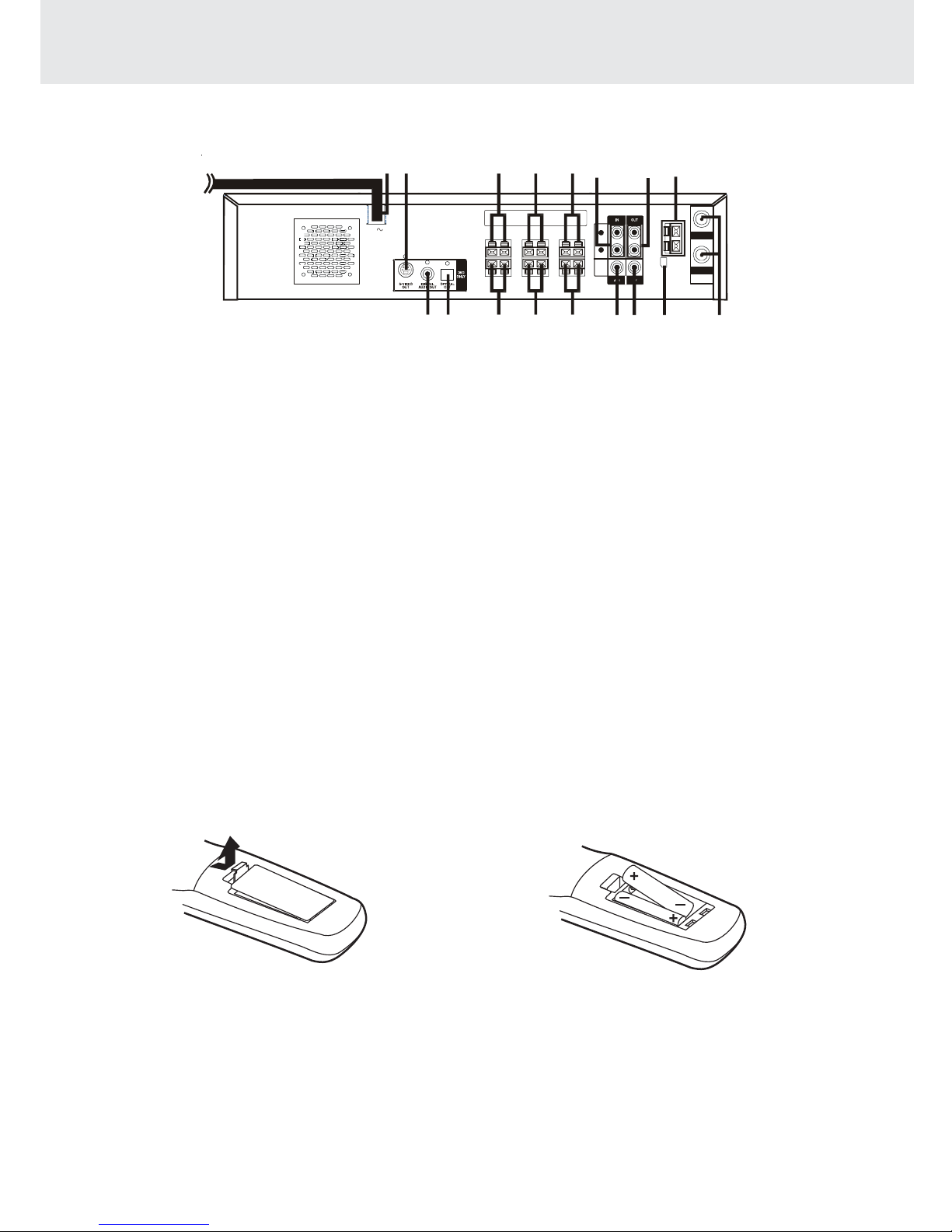
RearPanel..................................................................7
UsingtheRemoteControl........................................7
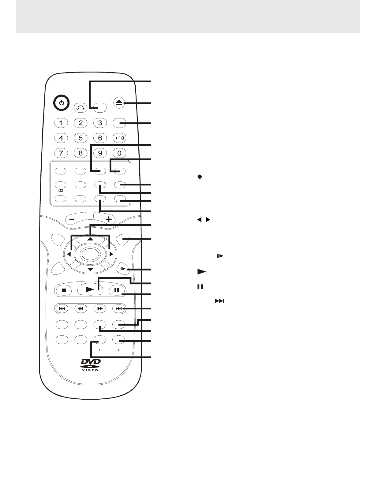
RemoteControl......................................................8-9
Display ......................................................... 10
FrontPanelDisplay..................................................10
DisplayInformation................................................10
Connections .......................................... 11-18
ConnectingyourTV.................................................11
CableTVConnections...............................12-15
ForbetterreceptionofRadio..................................15
Connectingthespeakers&subwoofer ..................16
Positioningthespeakersandsubwoofer..............16
Connectingotherequipment................................17
Mountingrearsurroundspeakers ..........................18
TurningontheUnitandTV ......................................18
Powercordconnection...........................................18
Adjusting the Sound ............................. 19-20
Playing a Disc ....................................... 21-24
Pausingplayback(stillmode)...............................21
Stoppingplayback.................................................21
Toskiptoadifferenttrack......................................21
FastFoward/FastReverse.....................................22
Slow-motionplay...................................................22
Skip(Forward)........................................................22
Zoomingintoanimage .........................................22
Angleselection.......................................................23
Audioselection.......................................................23
Subtitleselection....................................................24
IMPORTANT
This Unit does NOT allow
copying from DVD to VCR tape
CD/DVDprogrammable memory...............28
DVDprogrammablememory.................................28
Title/Chapterprogrammedplayback.............28
CDprogrammablememory...................................28
Trackprogrammedplayback..........................28
Special Functions ................................. 25-27
Displayfunction(DVD)..........................................25
GOTOfunction(DVD)...........................................25
Locatingaspecifictitle .........................................26
Locatingaspecifictitle/chapter/track..................26
Locatingaspecifictime.........................................27
Anglesetting...........................................................27
Audiosetting..........................................................27
Subtitlesetting.......................................................27
Repeat Playback ................................... 29-30
Repeatingatitle/chapter(DVD)............................29
Repeatingasingletrack/wholedisc(CD)...........29
Repeatingaspecificsection(DVD)......................30
Playing Picture File Disc............................. 31
PlayinganPicturefiledisc....................................31
CustomizingtheFunctionSettings ........32-40
LANGUAGEsetting..................................................32
VIDEOsetting............................................................33
TVShape..............................................................33
VideoOutput.......................................................34
Brightness............................................................34
Edges....................................................................35
AUDIOsetting...........................................................36
DigitalOut............................................................36
L/Rspeaker..........................................................36
Subwoofer............................................................37
SurroundDelay..................................................37
CenterDelay........................................................38
Pinknoise...........................................................38
VCR Setup ............................................. 39-47
MENUscreen............................................................39
OSD(OnScreenDisplay).......................................39
Howtodisplayindicators.................................39
Setup(withAutoClockSetting)............................40
Settingthe3 4OutputChannel...............41
ModeSelection...................................................42
ChannelPreset.........................................................43
Web Site (http://www.1800customersupport.com)

- 5 -
The unit can playback.
Region Management Information
Region Management Information: This unit is designed and manufactured to respond to the Region
Management Information that is encoded on DVD discs. If the Region number printed on the DVD disc does
not correspond to the Region number of this unit, this unit cannot play that disc.
The region number of this Unit is 1.
Disc Function or Operation that is Not Available
When the symbol appears on the TV screen, it indicates that the function or operation attempted is not
available at that time. This occurs because the DVD disc manufacturer determines the specific functions.
Certain functions may not be available on some discs. Be sure to read the documentation provided with the
DVD.
1
T
Chapter 1 Chapter 1Chapter 2 Chapter 2Chapter 3
DVDs
[8cm(3")/12cm(5”) disc]
Notes on Unauthorized Discs
You may not be able to play back some DVD discs on this unit if they were purchased from outside your
geographic area or made for business purposes.
Titles, Chapters and Tracks
• DVDs are divided into “titles” and “chapters”. If the
disc has more than one movie on it, each movie would
be aseparate “title”.“Chapters”aresections oftitles.
• Audio CDs are divided into “tracks”. A “track” is
usually one song on an Audio CD.
Note :
• Numbers identify each title, chapter, and track on a disc. Most discs have these numbers recorded on them,
but some do not.
Track 1 Track 2 Track 3 Track 4 Track 5
Icons Used on DVDs
Sample lcons Language selections for audio
Language selections for subtitles
Screen aspect ratio
Multiple camera angles
Region code indicator
2
2
2
1. English
2. French
1. English
2. French
Notes:
•Thisunit supports 2-channel(L/R) audio and 5.1ch(Multi-channel) MPEG Audio1/2(only whentheDIGITAL
AUDIO OUT coaxial jack is used for connection). It does not support 7.1 channel MPEG Audio Version 2.0.
• When playing back a CD-G (Graphics) or CD EXTRA disc, the audio portion will be played, but the graphic
images will not be shown.
Disc Formats
Compatible
Audio CDs
[8cm(3")/12cm(5”) disc]

- 6 -
1) POWER/ STANDBY button
Turn the power on or off.
2) STOP button (for VCR)
Stop playing a tape.
3) PLAY button (for VCR)
Press to start or resume playback
4) CHANNEL button UP/ DOWN (for VCR)
Use to highlight selections on a menu screen and
adjust certain setting.
5) Video cassette compartment
Open tray by pushing TAPE EJECT button.
6) Disc tray
Open or close tray by pushing DVD OPEN/CLOSE
button. Place a disc on the disc tray, label side up.
7) DVDOPEN/CLOSEbutton
Use to open and close the disc tray.
8) VOLUMEcontrol
Changetheloudnessofthesoundfromthespeakers
connected to the unit.
9) Displaywindow
Display system information.
10) FUNCTION button (DVD/RADIO/VCR)
Select the source.
11) PLAY button (for DVD)
Press to start or resume playback
12) PAUSE/ STOP/REW/F.FWbutton(forDVD)
Press to pause playback. Each time you press the
PAUSE button the picture advances one frame.
Press the PLAY button to resume playback.
Stop playing a disc.
Fast reverse and forward playback.
13) POWER ON/ STANDBY indicator
WhentheUnitisturnedonbypressingthePOWER
ON/STANDBY button, the light will illuminate a few
Front Panel
seconds. If you press the POWER button on the
remote control, the Unit will turn off and go into
standby mode. The light will continue to illuminate.
14) VCR POWER/TIMER/VCR/REC indicator
VCRPOWER:Thisindicatorlightsupwheneverthe
VCR is turned on.
TIMER:ThisindciatorlightsupwhentheVCRisset
for timer recording. Simple Recording Timer and
Recording with the Timer.
VCR:Thisindicatorlightsupwhenselecting"VCR"
by using TV/VCR.
REC : This indicator lights up during recording and
flashes during REC-Pause.
15) SET/MENU/REW/F.FWD button (for VCR)
SET:ConfirmselectionsonaVCRmenuscreen.
MENU : Use to select various screen functions.
REW : Fast reverse playback.
F.FWD : Fast forward playback.
16) REC button (for VCR)
Record a programme from TV or other sources
(except DVD).
17) VCRON/OFFbutton
Turn the VCR on or off.
18) TAPE EJECT button (for VCR)
Use to eject the tape.
19) Remote sensor
Accept the remote control unit signals.
20) VIDEO IN/AUDIO IN (L/R) jacks (AV 2 IN)
VIDEO IN : Connect a cable coming from the video
out jack of a camcorder, another VCR, or an audio
visual source here.
AUDIOIN(L/R):Connectaudiocablescomingfrom
theaudiooutjacksofacamcorder,anotherVCR,or
an audio source here.
Parts and Functions
Note:
Screensaver- Ifnobuttonispressed within2minutes, thescreensave functionwillactivate forDVDonly, Ifyouwant
to return to the normal screen, press any button.
(Continued on next page)(Continued on next page)
(Continued on next page)
1234 5 6 7
8
9101112131516 14
1718
19
20

- 7 -
Rear Panel
21) Power cord
22) S-VIDEO (DVD) output jack
23) Right Front speaker terminals
24) Centre speaker terminals
25) Left Front speaker terminals
26) AV1 IN (AUDIO) jacks
27) Left/Right AUDIO OUT jacks
28) FM ANTENNA jacks
29) VHF/UHF/CATV IN/OUT jacks
30) AM LOOP ANTENNA terminal
31) TV OUT (VIDEO) jack
32) VIDEO IN (VCR) jack
33) Left Rear speaker terminals
34) Subwoofer speaker terminals
35) Right Rear speaker terminals
36) OPTICAL OUT jack (DVD)
37) DIGITAL AUDIO OUT jack (DVD)
(Continued on next page)(Continued on next page)
(Continued on next page)
R
L
AUDIO
VIDEO
AM
LOOP
ANT.
FM ANT.
300
()
Ω
IN
OUT
VHF/UHF/
CATV
AC
2122 23 24 25 26 27 28
293031323334353637
Parts and Functions
ToinstallBatteries
1.Open the battery door.
BatteryReplacement
When batteries become weak, the operating distance of the Remote Control is greatly reduced and you will
need to replace the batteries.
Notes:
• If the Remote Control is not going to be used for a long time, remove the batteries to avoid damage caused
by battery leakage corrosion.
• Do not mix old and new batteries. Do not mix ALKALINE, standard (CARBON-ZINC) or rechargeable
(NICKEL-CADMIUM) batteries.
2.Insert two "AA" or UM-3 size batteries.
Using the Remote Control
• Point the Remote Control at the REMOTE SENSOR located on the Unit.
• When there is a strong ambient light source, the performance of the infrared REMOTE SENSOR may be
degraded, causing unreliable operation.
• The recommended effective distance for remote operation is about 16 feet (5 meters).
Notes:
• S-video out, Digital audio out and Optical out are only for the DVD section.

- 8 -
Parts and Functions
1) POWER / button
Turns the Unit on and puts it in standby mode.
2) RETURNbutton
ReturntothenormaloperationafterusingtheSETUPmenu.
3) Number (0 - 9) and AM/PM (+10) buttons
Use when creating programs, and entering a parental level
password. To select numbers over 9, press +10 button and
then the second no. for example, to enter 18, press +10 and
then 8.
AM/PM : Select AM or PM during time setting.
4) 5.1Chbutton
Switch speaker output to 5.1 channel mode. (All speakers +
subwoofer)
5) MEMORYbutton
Enter the number of a selected chapter or track.
Enter the number of a selected station.
Enter the number of a selected channel.
6) VCR STOP button
Stop playback.
7) CHANNEL +/- buttons
Select the desired channel.
8) PROLOGICbutton
In AV_IN mode, switches to Dolby Pro Logic mode for VHS
tapes encoded with Dolby Pro Logic.
9) VOLUME (+ / -) buttons
Adjust the volume.
10) ENTERbutton
Confirm selections on a menu screen.
11) SETUPbutton
Selects the SET UP menu screen.
12) / CURSOR buttons
Use to highlight selections on a menu screen and adjust
certain settings.
13) VCRON/OFFbutton
Turns the VCR on and off.
14) TUNING buttons
:Fast reverse playback of DVDs/VCRs.
:Fast forward playback of DVDs/VCRs.
TUNING : Scan all available radio stations.
15) STOP button (for DVD/VCR)
Stop playback.
16) PREV button (for DVD/VCR)
Move reverse through titles, chapters or tracks on a disc.
Tune to the presetted stations.
Set a reverse video search time.
17) CLEARbutton
Clearinputselectionsandcancelcertainplaybackfunctions.
18) DISPLAYbutton
Change disc status information displayed on the TV.
Change the screen as your desired.
19) ANGLE button
Switch the camera angle of the video presentation when
sceneswithmultiple cameraanglesarerecordedonaDVD.
20) SUBTITLEbutton
.....
SelectoneofthesubtitlelanguagesprogrammedonaDVD.
(Continued on next page)(Continued on next page)
(Continued on next page)
Remote Control
POWER
RETURN
OPEN/
CLOSE
FUNCTION
GOTO
AM/PM
VOLUME
SETUP MENU
ENTER
STOP
PREV
CLEAR
ANGLE SUBTITLE FM MODE BAND
A-B DISC
DISPLAY ZOOM AUDIO
TUNING NEXT
PLAY PAUSE
REPEAT
CH+
CH- SP .EP
INPUT TV/VCR
REC
MEMORY SOUND
PRO LOGIC
2.1 CH5.1 CH
SLOW
VCR STOP
VCR
ON/OFF
1
2
3
4
5
6
7
8
9
10
11
12
13
14
15
16
17
18
19
20

- 9 -
21) FUNCTIONbutton
Display the FUNCTION screen where you can check
or change various setting.
22) OPEN / CLOSE button (for DVD)
Use to open or close the disc tray.
23) GOTObutton
Skip directly to a specific location on a DVD disc.
24) 2.1 CH button
Switchspeakeroutputsto2.1channel.(Frontleft/right
speakers + subwoofer)
25) SOUNDbutton
Selectssoundbalanceandtonecontrolsforadjustment
with the cursor buttons.
26) TV/VCRbutton
Use to select TV or VCR position.
27) INPUTbutton
Dub video material from another video device.
28) REC button (for VCR)
RecordaprogrammefromTVorothersources(except
DVD).
29) SP • EP button
Select a recording speed (SP=standard play,
EP=extended play).
30) / CURSOR buttons
Use to highlight selections on a menu screen and
make adjust certain settings.
31) MENU button
Open and close DVD's menu.
32) SLOW button (for DVD/VCR)
Perform slow forward playback.
33) PLAY button (for DVD/VCR)
Start playback.
34) PAUSE button (for DVD/VCR)
Pause playback, frame advance.
35) NEXT button (for DVD/VCR)
Move forward through titles, chapters or tracks on a
disc.
Tune to the presetted stations.
Set a forward video search time.
36) AUDIObutton
Select one of the audio soundtracks programmed on
a DVD or selects the audio output mode on a AUDIO
CD.
37) ZOOMbutton
Zoom into an image.
38) BAND/REPEAT-DISC button
Switch between AM or FM.
Repeat chapter or title of a DVD.
Repeat single track or whole CD.
39) FM MODE / REPEAT A - B button
SetFM MODE toFM STEREOfor FM stereosound or
to FM MONO for mono sound.
Perform point-to-point repeat playback on a DVD or
CD.
Parts and Functions
Remote Control
POWER
RETURN
OPEN/
CLOSE
FUNCTION
GOTO
AM/PM
VOLUME
SETUP MENU
ENTER
STOP
PREV
CLEAR
ANGLE SUBTITLE FM MODE BAND
A-B DISC
DISPLAY ZOOM AUDIO
TUNING NEXT
PLAY PAUSE
REPEAT
CH+
CH- SP .EP
INPUT TV/VCR
REC
MEMORY SOUND
PRO LOGIC
2.1 CH5.1 CH
SLOW
VCR STOP
VCR
ON/OFF
21
22
23
24
25
26
27
28
29
30
31
32
33
34
35
36
37
38
39

- 10 -
Region (Local) Number Error Indicator
Iftheregion(local)numberofthediscthatyouattempttoplaydiffersfromtheregionnumberoftheUnit,"InvalidRegion"
appears on the TV screen. (The disc cannot be played).
If no disc is loaded
whentheMainUnit
is switched on.
Tray open
Tray closed
Loading
Stopped
Playing
Paused
Fast forward
Fast reverse
Slow
Repeat A - B
Remarks
"" appears when the tray is closed and:
1)There is no disc in the tray.
2)The disc type is not playable in this Unit.
3)The disc is not loaded correctly (upside-down, etc.)
The display changes to show
other indicators (total time, etc.)
Freezestheimageonthe screenorpauses audioplayback.
The display changes to show other indicators (total
time, etc.)
Does not function for Audio CDs.
Repeat a specific section.
The operation is not permitted by the DVD Unit or the
disc.
TV Screen Unit Display
No Disc
Stop
Play
Pause
x 2
x 2
x 1/2
/
Loading...
A-B
B
ANGLE indicator
Appears when multiple camera angles
are recorded in the section of the DVD
that is currently playing.
TITLE indicator
WhenaDVDisloadedin
the Unit, this indicator
appears along with the
title number.
CHAPTER /TRACK indicator
When a DVD is loaded in the
Unit, this indicator appears
along with the chapter number.
When a Audio CD is loaded in
the Unit, this indicator appears
along with the track number.
DOLBY DIGITAL
indicator
Displays while Dolby
Digital sound
processing is being
performed or when
the loaded disc
contains Dolby
Digital sound
OPERATION indicator
Indicates the operation status of the disc and Unit.
REPEAT 1
playback
indicator
Displayed
during
repeat
playback.
Display
Front Panel Display
Display Information
The DVD displays the information shown below on the TV screen and on the Unit's DVD display depending
on the operation status.
Display Examples
Open
A -
R. TOTAL(REMAIN.TOTAL)
indicator
Indicates the elapsed playback time
ofthedisc.Withsomediscs, thisarea
also shows the total play time of the
disc when playback is stopped.
REPEAT A-B playback
indicator
Displayed during repeat
playback.
MEMORY
indicator
Displayed
during
programmed
playback.
Close
STEREO indicator
Tune into a station. "((ST))"
will appear when an FM
broadcast is in stereo.
Turn on VCR In VCR mode.

- 11 -
Connections
(continued to next page)(continued to next page)
(continued to next page)
1. Connecting to your TV
The Unit can be connected to your TV in several different ways, depending on the design of your TV.
1. Connect the TV antenna (coaxial cable) to the input jack on the unit.
2. Attach one end of the supplied coaxial cable to the output jack on the unit, and the other end of the cable to the
input jack on your TV.
Alternate Connections:
1. If your TV has Audio/Video inputs, you can also connect the unit to your TV using the supplied Audio/Video cord.
2. If your TV is equipped with an S-Video input, you can utilize the S-Video jack to connect the unit to your TV with
an S-Video cord (not supplied) instead of the yellow video cable. Please note that the S-Video and coaxial cable
connectionwillonlycarrythevideosignalfrom DVDplayback.VCRplaybackwillstillrequireyoutousethecoaxial
cable connection.
ToWallOutlet
Whenyouconnect thissystem
to your TV, be sure to turn off
the power and unplug both
unitsfrom thewalloutletbefore
making any connections. S-Video cable (not supplied)
Audio/Video cable
(supplied)
(Red)
(White)
(Yellow)
(Red)
(White)
(Yellow)
To Audio IN
To Video IN
Coaxial cable
(supplied)
CATV or
ANTENNA
Coaxial cable
(not supplied)
ANTENNA IN
(antenna or cable input)
AM
LOOP
ANT.
FM ANT.
300
()
Ω
IN
OUT
VHF/UHF/
CATV
AC
R
L
AUDIO
VIDEO
R
L
AUDIO
VIDEO
TV OUT
Note:
• When playback DVD via coaxial cable to TV alone, there will be no audio output from the TV. i.e. Sound comes
from 5 speakers plus the subwoofer only.

- 12 -
Connections
(continued to next page)(continued to next page)
(continued to next page)
Cable TV Connections
Your VCR is capable of receiving the following non-scrambled channels.
• Scrambled channels can be received with the cable box supplied by your cable TV company.
Preparation
Set the 3 4 Output Channel of theVCR to 3 or 4.
See Setting the 3 4 Output Channel.
First check your TV/CATV system
Step 1: Is yourTV cable compatible with theVCR?
•YES Go to Step 2
• NO Go to Step 3
Step 2: Does your CATV system have some or all channels scrambled?
•YES Go to
• NO Go to
Step 3: Does your CATV system have some or all channels scrambled?
•YES Go to
• NO Go to Step 4
Step 4: Choose the type below.
• Basic connection (only for descrambled CATV signals.) Go to - or
• To watch a CATV programme while recording a TV programme by using the A/B switch. Go to
A.Connection without a cable box
Connect as shown.Then plug in the power cords of the TV and cable box.
Rear of Unit
From CATV system
IN
OUT
VHF/UHF/
CATV
TV Rear
ANT/CABLE
Coaxial cable (supplied)

- 13 -
Connections
(continued to next page)(continued to next page)
(continued to next page)
B.Connection with cable box
1.
Connect as shown. With this connection, it is possible to record descrambled CATV signals. Then plug in the
power cords of the TV and cable box.
Rear of Unit
Cable Box
From
CATV
system
IN
OUT
VHF/UHF/
CATV
Coaxial cable (Not supplied)
IN OUT
TV Rear
ANT/CABLE
Coaxial cable (supplied)
2.
Connect as shown. With this connection, it is not possible to record CATV programmes which have been
scrambled, but is possible to record one channel and watch the other one.Then plug in the power cords of the
TV and cable box.
TV Rear
ANT/CABLE
Rear of Unit
From CATV system
IN
OUT
VHF/UHF/
CATV
Coaxial cable (Not supplied)
Cable Box
IN OUT
Coaxial cable (supplied)
Notes:
• If the cable box is turned off, it will not output any signals, thus making it impossible to record or view a programme
from the CATV system.
• In the case of the above connections, it is not possible to change channels using the remote control. Only the
cable box can be used to change channels.
• Only one channel at a time can be programmed for recording programmes with the timer. It is not possible to
watch a TV programme different from the one being recorded.
• Depending on which terminals the TV has, a separate combiner (mixer) or separator (splitter) may be necessary.
Notes:
• With the above connection, CURSOR or button of theVCR or the numbered buttons on the remote control
can be used to select channels.
• Depending on which terminals the TV has, a combiner (mixer) or separator (splitter) may be necessary.
• To record one channel and watch another, the VCR must be set to the TV mode.

- 14 -
Connections
(continued to next page)(continued to next page)
(continued to next page)
C. Connection with cable box, A/B switch and splitter
By using an A/B switch or splitter, it is possible to switch between the cable box and the VCR output.
For example, while recording a TV programme with the VCR, it is possible to watch a CATV programme (including
descrambled programmes) using the A/B switch.
• Connect as shown.Then plug in the power cords of the TV and cable box.
Rear of Unit
From
CATV
system
IN
OUT
VHF/UHF/
CATV
Coaxial cable (Not supplied)
Splitter
(Not supplied)
Cable Box
IN OUT
Coaxial cable (supplied)
TV Rear
ANT/CABLE
A/B switch
(Not supplied)
A
B
Using the A/B Switch
1.Set the A/B switch to the “A” position in the following situations.
• To watch a cable TV programme while recording another programme.
• To watch a scrambled cable TV programme.
• To watch a cable TV programme when the VCR is turned off.
Notes:
• Use the cable box to change channels.
• If you turn off the cable box, you cannot watch a CATV programme.
2.Set the A/B switch to the “B” position in the following situations.
• To playback a cassette on the VCR.
• To watch a programme which is being recorded with the VCR tuner.
• To watch a programme using the VCR tuner.

- 15 -
Connections
(continued to next page)(continued to next page)
(continued to next page)
D.Connection with two cable boxes, A/B switch and splitter
The following connection is necessary to record a cable TV programme (even those scrambled by a cable
company) while watching another cable TV programme. The following connection requires two cable boxes, a 2-
way splitter and an A/B switch.
• Connect as shown.Then plug in the power cords of the TV and cable box.
Rear of Unit
From
CATV
system
IN
OUT
VHF/UHF/
CATV
Coaxial cable
(Not supplied)
Coaxial cable (Not supplied)
Splitter
(Not supplied)
Cable Box 1
Cable Box 2
IN
IN
OUT
OUT
TV Rear
ANT/CABLE
A/B switch
(Not supplied)
A
B
Coaxial cable (supplied)
Using the A/B Switch
1.Set the A/B switch to the “A” position in the following situations.
• To watch a cable TV programme while recording another programme.
• To watch a cable TV programme when the VCR is turned off.
2.Set the A/B switch to the “B” position in the following situations.
• To playback a cassette on the VCR.
• To watch a programme being recorded , or to change (or watch) channels with the cable box 2. The output
channel of the cable box 2 and the VCR must be the same.
Notes:
• If you turn off the cable box, you cannot record or view a CATV programme.
• If you have questions regarding any connection procedure, please contact your cable company.
FM
Connect FM antenna (supplied) to the
FM ANTENNA jacks.
AM
Connect the AM loop antenna
(supplied) to the AM LOOP ANTENNA
terminals. Rotate the AM loop antenna
to obtain the best reception.
NOTE: Position this AM loop antenna
as far away as possible from this
system and from theTV.
2. For better reception of Radio
R
L
AUDIO
VIDEO
AM
LOOP
ANT.
FM ANT.
300
()
Ω
IN
OUT
VHF/UHF/
CATV
AC
FMANTENNA
ACPOWERCORD
AM(MW)LOOP ANTENNA(SUPPLIED)

- 16 -
Connections
(continued to next page)(continued to next page)
(continued to next page)
FRONT SPEAKERS
Place on both sides of the TV,
equal distances apart.
SUBWOOFER
Can be placed anywhere.
CENTER
Place on the top of
or below the TV.
SUB-
WOOFER
CENTER
FRONT
LEFT FRONT
RIGHT
REAR
RIGHT
REAR
LEFT
3.Connecting the speakers & subwoofer
1. The speaker cords have been color-coded to simplify connection. Just plug the POSITIVE (+) and NEGATIVE (-)
ends of each speaker wire into the corresponding jacks on the rear of the Unit, matching the color tube on the end
of the speaker wire to the color-coded connector.
2. Connect each of the speaker wires to the satellite speakers. The front left/right and rear left/right speakers are all
the same. However, make sure you connect to the center speaker (color) to the one speaker which is slightly longer
than the rest.
4. Positioning the speakers and subwoofer
REAR SPEAKERS
Place right beside or slightly
behind your listening position,
and a little higher than your ears.
AM
LOOP
ANT.
FM ANT.
300
()
Ω
IN
OUT
VHF/UHF/
CATV
AC
R
L
AUDIO
VIDEO
+
+
SUBWOOFER
REAR (RIGHT) REAR (LEFT)
CENTERFRONT (RIGHT) FRONT (LEFT)

- 17 -
Connections
(continued to next page)(continued to next page)
(continued to next page)
Notes:
• If the external equipment is a television and this audio system is closed to it, you may experience interference if the
tuner function is selected while the television is working.
• When you have selectedTUNER function, sound will ONLY come from the front left, right speakers and subwoofer.
• If you have a stereo VCR, make sure you set it in stereo mode.
• Due to copyright protection, DVD movies cannot be copied.If you copy a DVD movie onto a videotape, the resulting
copy will be unclear, with poor sound quality.This is NOT caused by a defective DVD system.
5. Connecting Other Equipment
You can connect other audio and/or video equipment to your unit in different ways.The following illustrations give
a few examples of the connection possibilities.
Analogueconnection
Digital connection
COAXIALOPTICAL
Camcorder
VCR
Sound
system
R
L
AUDIO
VIDEO
R
(Yellow) (Yellow)
(Yellow)
(Yellow)
(Yellow) (Yellow)
(White) (Red)
(White)
(Red)
(White)
(Red)
(White)
(Red)
(White)
(Red)
(White)
(Red)
(No need to connect)
(Noneed
to connect)
AUDIO IN
R
L
AUDIO
VIDEO
Optical digital cable (not supplied)
Coaxial digital cable (not supplied)
Rear of Unit Audio equipment with
optical/coaxial digital input jack
Rear of Unit Amplifier of stereo system, etc.
Front of Unit Rear of Unit
(VIDEO/AUDIOcable)
(VIDEO/AUDIOcable)
(VIDEO/AUDIOcable)
or (and)

- 18 -
Connections
Turning on the Unit and TV
1)Press the POWER/STANDBY button to turn the Unit ON, or
2)Press the /POWER button on the remote control while the Unit is in standby mode.
3)Turn on theTV by pressing its POWER button.
4)Select the channel on your TV corresponding to the VIDEO IN jack that the Unit is connected to. See TV User
guide for more information.
• If you have connected the Unit successfully, the DVD logo (start-up picture) will appear on your TV screen.
Power cord connection
• Make sure that all the components and speakers are connected correctly.
• To prevent electrical shock, match wide blade of plug to wide slot, fully insert.
• Be sure the AC power cord is disconnected and all functions are off before making connections.
• When you are not going to use the Unit for a long period of time, disconnect the power cord.
Mounting rear surround speakers
1) Mark the correct mounting position on the wall.
2) Insert a fixing screw(s) at the marked position on the wall.
3) Align the slot hole(s) of the speaker over the screw and pull the speaker downward until it is firmly hooked.
Need More Help?
DO NOT RETURN THIS TO THE STORE
Please call Customer Service at 1-800-252-6123 or
visit online help at http://www.1800customersupport.com

- 19 -
To adjust the surround sound balance while Pro Logic decoding is in effect
Use the remote control to make the following changes to speaker balance:
Front speaker (left)
• Press the SOUND button repeatedly to display LEFT, then press the or CURSOR button to adjust the
sound level. It will show on the display of the Unit.
Front speaker (right)
• Press the SOUND button repeatedly to display RIGHT, then press the or CURSOR button toadjust the
sound level. It will show on the display of the Unit.
Center speaker
• Press the SOUND button repeatedly to display CENTRE, then press the or CURSOR button to adjust
the sound level. It will show on the display of the Unit.
Rear speaker (left)
• Press the SOUND button repeatedly to display REAR L, then press the or CURSOR button to adjust the
sound level. It will show on the display of the Unit.
Rear speaker (right)
• Press the SOUND button repeatedly to display REAR R, then press the or CURSOR button to adjust the
sound level. It will show on the display of the Unit.
Subwoofer
• Press the SOUND button repeatedly to display WOOFER, then press the or CURSOR button to adjust
the sound level. It will show on the display of the Unit.
Note :
• If you do not press any button within a few seconds, the display will return to normal.
To adjust the sound quality
Press the SOUND button repeatedly to select an equalization mode (BASS, MIDDLE, TREBLE). Press the
or CURSOR button to adjust the sound level.
BASS : the low range of sounds
MIDDLE : the mid range of sounds
TREBLE : the high range of sounds
Bass, middle and treble control the sound from the front left and right speakers.
Adjusting the Sound
(continued to next page)(continued to next page)
(continued to next page)
DolbyDigital
DolbyDigital isa soundsystem developedbyDolbyLaboratoriesInc. thatgives movietheatre ambienceto audiooutput
when the Unit is connected to a Dolby Digital 5.1 channel processor or amplifier.
This Unit automatically recognizes DVDs that have been recorded with Dolby Digital.
Not all Dolby Digital sources are recorded with 6 channels.
Some sources marked Dolby Digital may be recorded in Dolby Surround, a 2 channel system. Look for this logo on your
DVD Unit.
Manufactured under license from Dolby Laboratories.
'Dolby' , 'Pro Logic' and the double-D symbol are trademarks of Dolby Laboratories.

- 20 -
Adjusting the Sound
The following tables show which speakers are working in the various modes.
REMARKS:
1) Generally, only Front Left, Right speakers and Subwoofer are active at TUNER mode.
2) " " The speakers is activated.
3) " X" The speakers is not activated.
4) AlwayskeepyourVCRinstereomodeotherwisethespeakersoutputstatusmaybedifferenttoabovelistedtable.
5) You can only set 5.1 CH, 2.1 CH when the disc is stopped.
6) In Subwoofer On mode, if speaker is set to "Large", then the output of subwoofer is low.
To select the listening channel
1.When the disc is stopped, you can press 5.1 CH and 2.1 CH buttons on the remote control to select different
speakers output status shown as below table.
2.You can active or off subwoofer output by setup menu.
Note:
The wording "2.1 CH" will be corresponded to the audio/sound output from Front Left and Front Right speaker
plus the Subwoofer.
5.1 CH /
2.1 CH Subwoofer L/R
Speaker Front Left
Speaker Front Right
Speaker Center
Speaker Subwoofer Rear Left
Speaker Rear Right
Speaker
Small
Large X
Small /
DVD Large
CD Small /
Large
Small /
Large
Audio Settings Speakers Output Status
DISC
ON5.1 CH
5.1 CH
2.1 CH
2.1 CH
OFF
ON
OFF
X
X
X
X
X
X
X
X
Output
Channel 3 Stereo /
Pro Logic Subwoofer L/R
Speaker Front Left
Speaker Front Right
Speaker Center
Speaker Subwoofer Rear Left
Speaker Rear Right
Speaker
TUNER N/A N/A N/A N/A XXX
ON Small
Pro ON Large X
Logic Small /
Large
ON Small XX
ON Large XXX
Small /
Large
Small /
Large
Small /
Large
3 CH
2 CH
VCR /
AV_IN
Audio Settings
Sources
OFF
3 Stereo OFF
OFF ON
OFF
4 CH
XXXX
XXX
XXX
Speakers Output Status
X
Table of contents