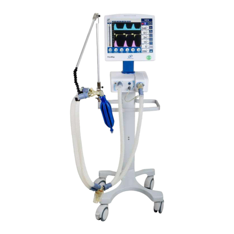
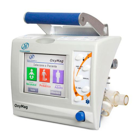
Magnamed FlexiMag Max 700 User manual

Operations Manual
Electronic Pulmonary Ventilator
FlexiMag Max 700
Fleximag Max 500
Fleximag Max 300

2
This operating manual includes the 3 models of pulmonary ventilators of FlexiMag Max’s family: Fleximag Max
700, Fleximag Max 500 and Fleximag Max 300 developed and manufactured by Magnamed Tecnologia
Medica S / A.
Review of this operation manual: 02
ANVISA Registration nº 80659160005
All rights reserved by:
Magnamed Tecnologia Médica S/A
Rua Santa Mônica, 801, 831
06715-865 –Parque Industrial San José -Cotia –SP Brazil
Tel/Fax: +55 11 4615-8500
E-mail: magnamed@magnamed.com.br
Website: www.magnamed.com.br
CNPJ: 01.298.443/0002-54
State registration: 149.579.528.111
Technical Responsible: Toru Miyagi Kinjo
Inscription CREA-SP: 5061555031
Legal Responsible: Wataru Ueda

3
Table of Contents
1 SAFETY NOTES........................................................................................................................................................ 14
1.1 DEFINITIONS ...............................................................................................................................................................14
1.2 WARNING...................................................................................................................................................................15
1.3 ATTENTION.................................................................................................................................................................17
1.4 OBSERVATION .............................................................................................................................................................17
2 FEATURES............................................................................................................................................................... 18
2.1 INTENDED USE.............................................................................................................................................................18
2.2 PRINCIPLE OF OPERATION..............................................................................................................................................18
2.3 GENERAL FEATURES ......................................................................................................................................................20
2.4 TECHNICAL CHARACTERISTICS .........................................................................................................................................21
2.5 SAFETY FEATURES.........................................................................................................................................................22
3 UNPACKING THE PRODUCT .................................................................................................................................... 23
3.1 INITIAL VERIFICATIONS ..................................................................................................................................................23
3.2 LIST OF COMPONENTS...................................................................................................................................................23
3.3 OPTIONAL PARTS AND ACCESSORIES ................................................................................................................................25
4 IDENTIFICATION OF COMPONENTS........................................................................................................................ 27
4.1 FRONT VIEW...............................................................................................................................................................27
4.1.4 Front panel ......................................................................................................................................................28
4.2 BACK VIEW.................................................................................................................................................................29
4.3 VIEW FROM THE BOTTOM OF THE DISPLAY ........................................................................................................................30
5 PREPARATION FOR USE.......................................................................................................................................... 31
5.1 ASSEMBLY ..................................................................................................................................................................31
5.2 ELECTRICAL NETWORK CONNECTION................................................................................................................................41
5.3 VERIFICATION BEFORE USE ............................................................................................................................................42
6 INSTRUCTIONS FOR USE......................................................................................................................................... 44
6.1 INITIAL SEQUENCE........................................................................................................................................................44

4
6.2 RESTRICTED MENU .......................................................................................................................................................47
6.2.1 Restricted menu ...............................................................................................................................................47
6.2.1.1 Patient..........................................................................................................................................................................47
6.2.1.2 Autotest........................................................................................................................................................................47
6.2.1.3 Calibration....................................................................................................................................................................47
6.2.1.4 Status............................................................................................................................................................................48
6.2.1.5 Battery..........................................................................................................................................................................48
6.2.1.6 System..........................................................................................................................................................................48
6.2.1.7 Advanced......................................................................................................................................................................48
6.2.1.8 Ventilation....................................................................................................................................................................48
6.3 MAIN SCREEN.............................................................................................................................................................49
6.3.1 Battery status area ..........................................................................................................................................49
6.3.2 Patient information area..................................................................................................................................49
6.3.2.1 Volume x weight patient definition..............................................................................................................................49
6.3.3 Historical events area.......................................................................................................................................50
6.3.4 Alarm setting area ...........................................................................................................................................50
6.3.5 Mute alarm button...........................................................................................................................................50
6.3.6 Manual cycle button ........................................................................................................................................50
6.3.7 Inspiratory hold button ....................................................................................................................................50
6.3.8 Expiratory hold button .....................................................................................................................................51
6.3.9 O2+button (O2flush) ........................................................................................................................................51
6.3.10 Nebulizer / TGI button....................................................................................................................................51
6.3.11 Graphic freeze button ....................................................................................................................................51
6.3.12 Menu access area ..........................................................................................................................................51
6.3.12.1 Layout.........................................................................................................................................................................51
2 waveforms ........................................................................................................................................................................51
Big numbers.........................................................................................................................................................................51

5
Monitor................................................................................................................................................................................52
3 waveforms ........................................................................................................................................................................52
Lung .....................................................................................................................................................................................52
2 loops .................................................................................................................................................................................52
6.3.12.2 Resources ...................................................................................................................................................................52
6.3.12.2.1 Noninvasive Ventilation (NIV).........................................................................................................................53
6.3.12.2.2 External Auxiliary pressure .............................................................................................................................54
6.3.12.2.3 Tube compensation ........................................................................................................................................54
6.3.12.3 Maneuver...................................................................................................................................................................54
6.3.12.3.1 P0.1 .................................................................................................................................................................55
6.3.12.3.2 Slow Vital Capacity..........................................................................................................................................55
6.3.12.3.3 P/V Flex...........................................................................................................................................................55
6.3.12.3.4 Pi Max .............................................................................................................................................................56
6.3.12.3.5 Gas Trapping Volume......................................................................................................................................56
6.3.12.4 Trend..........................................................................................................................................................................56
6.3.12.5 Calibration..................................................................................................................................................................56
6.3.12.5.1 O2cell (galvanic cell only)................................................................................................................................57
6.3.12.6 Advanced....................................................................................................................................................................57
6.3.13 Lock Button ....................................................................................................................................................57
6.3.14 Stand by button..............................................................................................................................................57
6.3.15 Bargraph or monitored parameters area ......................................................................................................57
6.3.16 Graphics area .................................................................................................................................................57
6.3.17 Ventilation Mode Setting Area.......................................................................................................................58
6.3.17.1 Ventilatory modes available.......................................................................................................................................58
6.3.17.2 Adjusting ventilatory modes ......................................................................................................................................59
6.4 CALIBRATIONS .............................................................................................................................................................60
6.4.1 Distal Flow Sensor ............................................................................................................................................60
6.4.2 Integrated valve ...............................................................................................................................................60

6
6.4.3 O2cell (galvanic cell only).................................................................................................................................60
6.5 AUTOMATIC COMPENSATION OF THE RESPIRATORY CIRCUIT ..................................................................................................61
7 TROUBLESHOOTING............................................................................................................................................... 62
8 CLEANING, DISINFECTION AND STERILIZATION ...................................................................................................... 64
8.1 EXTERNAL PARTS..........................................................................................................................................................64
8.2 COMPONENTS .............................................................................................................................................................64
8.2.1 PROXIMAL flow sensor, silicone line and integrated valve ..............................................................................64
8.2.1.1 Wash ............................................................................................................................................................................64
8.2.1.2 Rinse.............................................................................................................................................................................65
8.2.1.3 Drying...........................................................................................................................................................................65
COMPOSITION OF THE ENZYMATIC DETERGENT.........................................................................................................................65
8.3 DISINFECTION..............................................................................................................................................................65
8.3.1 External Parts...................................................................................................................................................65
8.3.2 Exhalation valve, proximal flow sensor and silicone line .................................................................................66
8.3.3 Distal flow sensor (Envitec SpiroQuant A+)......................................................................................................66
8.3.4 IRMA CO2sensor ..............................................................................................................................................66
8.3.5 Oximetry sensor (oximeter)..............................................................................................................................67
8.4 STERILIZATION .............................................................................................................................................................68
8.4.1 Steam Sterilization ...........................................................................................................................................68
8.5 IMPORTANT ADVICES ....................................................................................................................................................68
8.6 PROCESSING METHODS.................................................................................................................................................70
9 PREVENTIVE MAINTENANCE .................................................................................................................................. 71
9.1 VERIFICATIONS ............................................................................................................................................................71
9.2 PREVENTIVE MAINTENANCE SCHEDULE ............................................................................................................................72
9.3 CONSUMABLE ITEMS.....................................................................................................................................................72
9.4 INTERNAL BATTERIES.....................................................................................................................................................72
9.5 WATER COLLECTORS WITH COALESCING FILTER..................................................................................................................73

7
9.6 MESH FILTER...............................................................................................................................................................74
9.7 O2CONCENTRATION CELL..............................................................................................................................................75
10 TECHNICAL SPECIFICATIONS................................................................................................................................. 77
10.1 CLASSIFICATION .........................................................................................................................................................77
10.1.1 Class I Equipment ...........................................................................................................................................77
10.1.2 Protection class of applied parts....................................................................................................................77
10.1.3 CE –Class IIB ..................................................................................................................................................77
10.1.4 ANVISA –Class III ...........................................................................................................................................77
10.1.5 FDA –Class II ..................................................................................................................................................77
10.2 APPLICABLE STANDARDS..............................................................................................................................................77
10.3 PHYSICAL AND ENVIRONMENTAL SPECIFICATIONS .............................................................................................................78
10.4 ELECTRICAL SPECIFICATIONS .........................................................................................................................................79
10.4.1 Electrical network ..........................................................................................................................................79
10.4.2 Batteries.........................................................................................................................................................80
10.4.3 External DC Power Supply ..............................................................................................................................80
10.4.4 Connectors .....................................................................................................................................................81
10.4.4.1 Protocol used for data communication with external devices...................................................................................82
10.4.5 Gas Inlet Connector........................................................................................................................................83
10.5 PNEUMATIC SPECIFICATIONS ........................................................................................................................................84
10.5.1 Pneumatic layout ...........................................................................................................................................84
10.6 INTERNAL FLOW TRANSDUCER SPECIFICATIONS................................................................................................................85
10.7 DISTAL FLOW SENSOR SPECIFICATIONS...........................................................................................................................86
10.8 PROXIMAL FLOW SENSOR SPECIFICATIONS ......................................................................................................................86
10.9 PRESSURE SENSOR SPECIFICATIONS................................................................................................................................86
10.10 GALVANIC O2CELL SPECIFICATIONS..............................................................................................................................87
10.11 PARAMAGNETIC O2CELL SPECIFICATION .......................................................................................................................88
10.12 VENTILATION MODES SPECIFICATIONS .........................................................................................................................89

8
10.12.1 VCV...............................................................................................................................................................89
10.12.2 PCV...............................................................................................................................................................91
10.12.3 PLV ...............................................................................................................................................................93
10.12.4 PRVC.............................................................................................................................................................95
10.12.5 V-SIMV .........................................................................................................................................................97
10.12.6 P-SIMV........................................................................................................................................................100
10.12.7 CPAP/PS .....................................................................................................................................................103
10.12.8 DualPAP .....................................................................................................................................................106
10.12.9 APRV...........................................................................................................................................................109
10.12.10 MMV ........................................................................................................................................................111
10.12.11 VS .............................................................................................................................................................112
10.12.12 Nasal CPAP...............................................................................................................................................113
10.12.13 NIV ...........................................................................................................................................................113
10.12.14 VG.............................................................................................................................................................114
10.12.15 O2THERAPY..............................................................................................................................................115
10.13 OXYGEN ADJUSTMENT RESPONSE TIME .......................................................................................................................116
10.14 ACCURACY OF SETTINGS...........................................................................................................................................116
10.15 ADJUSTABLE PARAMETER SPECIFICATIONS ..................................................................................................................117
10.16 MONITORED PARAMETER SPECIFICATIONS..................................................................................................................120
10.17 SAFETY SYSTEM SPECIFICATIONS ...............................................................................................................................122
10.18 ALARM SYSTEM SPECIFICATION.................................................................................................................................123
10.18.1 Adjustable alarm specifications .................................................................................................................124
10.18.2 Ventilator alarm messages ........................................................................................................................125
10.18.3 Ventilator Alert Messages..........................................................................................................................128
10.18.4 IRMA CO2 sensor alarm messages..............................................................................................................129
10.18.5 Oximeter Alarm Messages .........................................................................................................................131
10.18.6 Alarm Testing .............................................................................................................................................132

9
10.18.6.1 FiO2alarm...............................................................................................................................................................132
10.18.6.2 Airway pressure alarm ...........................................................................................................................................133
10.18.6.3 Volume alarm.........................................................................................................................................................133
10.18.6.4 No AC power alarm ................................................................................................................................................133
10.18.6.5 Low battery alarm ..................................................................................................................................................133
10.18.6.6 Gas supply failure alarm.........................................................................................................................................133
10.18.6.7 PEEP alarm .............................................................................................................................................................133
10.18.6.8 Disconnection alarm...............................................................................................................................................133
10.18.6.9 Obstruction alarm ..................................................................................................................................................134
10.18.6.10 Minute volume alarm...........................................................................................................................................134
10.18.6.11 Respiratory rate alarm .........................................................................................................................................134
10.18.6.12 Apnea alarm.........................................................................................................................................................134
10.18.6.13 EtCO2alarm..........................................................................................................................................................134
10.18.6.14 ICO2alarm ............................................................................................................................................................135
10.18.6.15 Heart rate alarm...................................................................................................................................................135
10.18.6.16 SpO2alarm............................................................................................................................................................135
10.18.7 Battery test ................................................................................................................................................135
10.19 PERFORMANCE SPECIFICATIONS ................................................................................................................................135
10.20 RESPIRATORY CIRCUIT SPECIFICATIONS.......................................................................................................................136
10.21 MAINTENANCE AND CALIBRATION SPECIFICATIONS .......................................................................................................137
10.22 IRMA CO2SENSOR SPECIFICATIONS .........................................................................................................................137
10.23 OXIMETER SPECIFICATIONS.......................................................................................................................................140
10.24 ELECTROMAGNETIC COMPATIBILITY ...........................................................................................................................141
10.24.1 Guidelines and manufacturer's declaration - Electromagnetic emissions .................................................142
10.24.2 Guidelines and manufacturer's declaration - Electromagnetic immunity..................................................142
10.24.3 Electrical safety ..........................................................................................................................................146
10.25 AUDIBLE ACOUSTIC ENERGY......................................................................................................................................146

10
10.26 MASK TO NON-INVASIVE VENTILATION .......................................................................................................................146
10.27 RESPIRATORY CIRCUIT.............................................................................................................................................147
10.28 HME FILTER .........................................................................................................................................................147
10.29 HEPA FILTER ........................................................................................................................................................148
11 IRMA CO2 SENSOR (OPTIONAL) .......................................................................................................................... 149
11.1 INTENDED USE.........................................................................................................................................................149
11.2 INSTRUCTIONS FOR USE .............................................................................................................................................149
11.2.1 Reset procedure ...........................................................................................................................................150
11.2.2 LED status information.................................................................................................................................151
11.3 PREVENTIVE MAINTENANCE........................................................................................................................................151
11.4 IMPORTANT NOTICES................................................................................................................................................151
12 PULSE OXIMETER (OPTIONAL)............................................................................................................................ 153
12.1 INTENDED USE.........................................................................................................................................................153
12.2 PRINCIPLE OF OPERATION..........................................................................................................................................153
12.3 IMPORTANT NOTICES................................................................................................................................................155
13 TECHNICAL SERVICE ........................................................................................................................................... 157
14 DISCARD............................................................................................................................................................. 158
15 SYMBOLOGY ...................................................................................................................................................... 159
15.1 SYMBOLS USED IN THE EQUIPMENT..............................................................................................................................159
15.2 SYMBOLS USED IN PACKAGING AND LABELING ................................................................................................................160
16 ABBREVIATIONS AND TERMS USED.................................................................................................................... 162
17 BIOCOMPATIBILITY STATEMENT ........................................................................................................................ 164
18 WARRANTY ........................................................................................................................................................ 165
19 TRAINING........................................................................................................................................................... 166
ANNEX I –DIFFERENCES BETWEEN MODELS ........................................................................................................... 167

11
Table index
Table 1 - Initial Verifications.............................................................................................................................23
Table 2 - Components that accompany FlexiMag Max ...................................................................................23
Table 3 - OPTIONAL parts and accessories....................................................................................................25
Table 4 - Verification before use......................................................................................................................42
Table 5 - Ventilatory modes.............................................................................................................................58
Table 6 –Sterilizable accessories ...................................................................................................................68
Table 7 –Processing methods ........................................................................................................................70
Table 8 –Preventive maintenance schedule...................................................................................................72
Table 9 –Consumable items replacement ......................................................................................................72
Table 10 - Physical and environmental specifications.....................................................................................78
Table 11 –Electrical network...........................................................................................................................79
Table 12 - Batteries..........................................................................................................................................80
Table 13 –External DC power supply .............................................................................................................80
Table 14 - Connectors......................................................................................................................................81
Table 15 - Gas Inlet Connector........................................................................................................................83
Table 16 - Internal Flow Transducer - General Specifications.........................................................................85
Table 17 - Distal Flow Sensor - General Specifications ..................................................................................86
Table 18 - Proximal Flow Sensor - General Specifications ADULT ................................................................86
Table 19 - Pressure sensor - General specifications.......................................................................................86
Table 20 –Galvanic O2cell specifications.......................................................................................................87
Table 21 –Paramagnetic O2 cell specification.................................................................................................88
Table 22 –Oxygen adjustment response time ..............................................................................................116
Table 23 –Accuracy of settings.....................................................................................................................116
Table 24 –Uncertainty of settings .................................................................................................................117
Table 25 - Adjustable parameters..................................................................................................................117
Table 26 - Monitored ventilatory parameters.................................................................................................120

12
Table 27 - Alarm Priority ................................................................................................................................123
Table 28 - Alarms Characteristics..................................................................................................................123
Table 29 - Adjustable alarms .........................................................................................................................124
Table 30 - High priority alarms.......................................................................................................................125
Table 31 - Medium Priority Alarms.................................................................................................................126
Table 32 - Low priority alarms........................................................................................................................127
Table 33 - Alert messages.............................................................................................................................128
Table 34 - High priority alarms.......................................................................................................................129
Table 35 - Medium Priority Alarms.................................................................................................................130
Table 36 - Low priority alarms........................................................................................................................130
Table 37 - High priority alarms.......................................................................................................................131
Table 38 - Medium Priority Alarms.................................................................................................................131
Table 39 - Low priority alarms........................................................................................................................132
Table 40 - Performance specifications...........................................................................................................135
Table 41 - Expiratory and inspiratory branch resistance specifications.........................................................136
Table 42 - Respiratory circuit compliance specification.................................................................................136
Table 43 - Operation Specifications...............................................................................................................137
Table 44 - Maintenance and calibration specifications..................................................................................137
Table 45 - IRMA CO2sensor - General specifications...................................................................................137
Table 46 - IRMA CO2Sensor - Outputs.........................................................................................................138
Table 47 - IRMA CO2sensor - Gas analyzer.................................................................................................138
Table 48 - IRMA CO2sensor –Accuracy I ....................................................................................................139
Table 49 - IRMA CO2sensor - Accuracy II ....................................................................................................139
Table 50 - IRMA CO2sensor - Effects of gas and vapor interference...........................................................139
Table 51 –Quantitative effects of humidity and condensation......................................................................140
Table 52 –Performance specifications..........................................................................................................140
Table 53 –Environmental specifications .......................................................................................................140

13
Table 54 –Audible acoustic energy specification..........................................................................................146
Table 55 –Mask to NIV ventilation specification ...........................................................................................146
Table 56 –Respiratory circuit specification ...................................................................................................147
Table 57 –HME filter specification ................................................................................................................147
Table 58 –HEPA filter specification...............................................................................................................148
Table 59 - IRMA CO2Status LEDs................................................................................................................151
Table 60 - Symbols used in the equipment....................................................................................................159
Table 61 - Symbols used in packaging and labeling .....................................................................................160
Table 62 - Abbreviations and terms used......................................................................................................162

14
1 Safety Notes
1.1 Definitions
•Informs the user of the possibility of injury, death or other serious adverse reaction
associated with the use or misuse of the equipment.
•Informs the user of the possibility of equipment failure associated with the use or
misuse, such as: malfunction, damage to the equipment itself, damage to third party
assets and indirect injury to the patient.
•Important information to observe.

15
1.2 Warning
•Whenever there is a symbol, consult this manual for more information.
•This manual shall be read in its entirety carefully to ensure correct and safe use of the
equipment and to provide maximum safety and the best resources to the patient.
Observe all "WARNING" and "ATTENTION" contained in this manual and on the
labeling of the equipment.
•The equipment shall be used only for the purpose specified in Intended Use (Chapter
2.1) and with appropriate monitoring.
•The equipment shall be operated by trained and qualified personnel, who shall maintain
vigilance during use, including in volume limited ventilation, so that in case of
malfunction or failure, help is available immediately.
•Explosion Hazard: This equipment is not approved for use with flammable anesthetic
agents.
•Equipment may be adversely affected and may be subject to interference from certain
transmitting equipment, such as cellular telephones, walkie-talkie, cordless telephones,
pagers, high frequency surgical equipment (diathermy), and shortwave therapy, which
may interrupt the operation of the equipment. Do not use this transmission equipment
near the ventilator.
•This equipment shall not be used during a nuclear magnetic resonance (MTR, NMR,
NMI), as it may cause interference, causing adverse effects to the patient.
•Before first use or after use on each patient, clean the equipment as indicated in chapter
8.
•When powering up the equipment, perform basic scanning and adjustment procedures.
Follow the instructions in chapter 5.
•ALARMS and WARNINGS shall be promptly serviced in order to maintain the integrity
of the equipment operation and patient safety.
•Do not use electrically conductive antistatic hoses or tubes in the respiratory system
of the ventilator.
•Always check that the equipment is correctly set before using it.
•After starting the ventilation, using monitoring verify if ventilatory parameters are
adequate.
•Use only MAGNAMED accessories listed in this manual, which have been tested and
approved for use in conjunction with this equipment. Otherwise, functionality of the
equipment may be compromised.
•During prolonged use of the equipment with patients with excess secretion and / or
using a heated humidifier, the condition of the flow sensor shall be checked frequently,

16
attempting to drain accumulated fluids in the respiratory circuit when necessary.
•Keep the equipment connected to an electrical source even when it is turned off, so
that the internal batteries are always charged.
•After using the equipment or after an extended period of storage, fully recharge the
batteries.
•If LOW BATTERY alarm occurs, IMMEDIATELY connect the ventilator to an electrical
Network. If this is not possible, provide another suitable means of ventilatory support
and then DISCONNECT patient equipment.
•Recharge the batteries before the next use, otherwise, any electrical power failure may
interrupt the operation of the ventilator.
•Always check that there are no obstructions, as it is extremely important for a correct
monitoring of ventilatory parameters that the respiratory circuit is completely
unobstructed.
•Never obstruct the pressure connections. The pressures measured at these points are
used by the patient monitoring system.
•After use, reusable respiratory circuit components shall go through a high-level
disinfection process before their next use.
•All parts of the equipment that come in contact with fluids from the patient SHALL be
discarded, disinfected, sterilized or disposed of as potentially infectious hospital waste.
•All parts of the FlexiMag Max that are in the gas passage way, including accessories
and applied parts, are made of non-toxic, latex-free and phthalate-free material and do
not cause irritation or allergy to the patient.
•Common use non-exclusive FlexiMag Max accessories, such as masks, circuits,
nebulizers, humidifiers, HME filters, among others, shall be registered with local
government.
•Do not use the equipment if a problem cannot be solved.
•Have a manual ventilation device available for the case of complete discharge of the
battery, lack of gases for the operation of the device or even for general failure of the
ventilator. The absence of manual ventilation in these cases may result in death of the
patient.
•Always use officially approved oxygen cylinders and pressure reducing valves that
meet local government requirements.
•For proper ventilation, when adjusting the ventilator, take into consideration the dead
spaces of the respiratory circuit, especially for low tidal volumes.
•The ventilator shall not be covered or positioned in such a way that operation or
performance is affected.
•When components of the respiratory circuit or other components or subassemblies are
added to the respiratory system of the ventilator, the pressure gradient across the
respiratory system, measured relative to the patient's port of attachment, may increase,
adversely affecting the performance of the ventilator.

17
•Nebulization or humidification can increase the resistance of respiratory system filters.
The operator shall often monitor increased resistance and filter blockage of the
respiratory system.
•The ventilator cannot be used in a hyperbaric chamber.
•Only use air and oxygen in the gas inlet of the equipment. Do not use nitric oxide,
helium or other gases.
•The expiratory branch may become contaminated with bodily fluids or expired gases
during use of the equipment under normal conditions and under a single fault.
•HME filter, HEPA filter and airway adapter are single use. The reuse of these
accessories may cause cross contamination.
•The distal flow sensor is for single patient use and shall be discarded when changing
patients. Re-use for another patient may result in cross-contamination.
•FlexiMag Max does not generate sub atmospheric pressure during the expiratory phase.
1.3 Attention
•This ICU ventilator does not emit electromagnetic waves that may interfere with the
operation of equipment in its vicinity.
•Perform all maintenance according to the operating time specified in this manual.
•All service, modification or maintenance on the ventilator can only be carried out by
qualified technician, trained and duly authorized by MAGNAMED.
•Only use parts, cables, sensors, filters and breathing circuits specified by MAGNAMED
and compatible with the system. For purchase, please inform the codes presented in
the corresponding chapter.
1.4 Observation
•The technical specifications of MAGNAMED products are subject to change without notice.

18
2 Features
2.1 Intended Use
FlexiMag Max’s ventilator family has been developed to provide invasive and non-invasive ventilatory
support with complete ventilatory monitoring for neonatal, pediatric and adult patients with impaired respiratory
function in postoperative intensive care units in post-anesthetic recovery rooms (RPA), or for in-hospital
transport.
2.2 Principle of Operation
FlexiMag Max is a family of a micro processed electronic lung ventilators whose principle of operation
is based on the integration between specific modules:
•Pneumatic module (manifold)
•Electronic Control Module
•Electronic interface module
At the entrance of the pneumatic module, two valves regulate the pressure of the gases coming from
the hospital network or cylinders, trying to assure a suitable range to the equipment.
Together with these regulating valves, there are microswitches or limit switches that constantly monitor
the gas pressure, so that the insufficiency or absence of pressure of one or both gases is immediately indicated
by a priority alarm.
Subsequently, electronically controlled air
1
and O2proportional valves regulate the flow of gases
accurately to ensure concentration and volume appropriate to each situation.
For the models Fleximag Max 300 and Fleximag Max 700, the ventilator relies on the FlowAir system
2
,
consisting of a turbine to electronically control the flow of air.
After their respective flows are adjusted, the gases are mixed to make the measurement of the O2
concentration and the measurement of the resulting flow.
The O2concentration is obtained through a galvanic cell or optionally, a paramagnetic cell by indirect
contact with the gas of the patient, through the passage of gas in the sensor.
1
Only for Fleximag Max 500 and Fleximag Max 700 models
2
Only for Fleximag Max 300 and Fleximag Max 700 models

19
The resulting flow measurement is performed by a high precision internal flow sensor, which
guarantees an adequate reading, without the need for recalibrations and has mass flow technology, whose
reading is independent of temperature or pressure.
The flow expired by the patient is measured by an external sensor, of the thermal type or hot wire
anemometer, connected to the expiratory valve. Optionally, this flow can be read through a proximal flow
sensor, connected to the patient's "Y" output, whose measurement is based on the pressure differential
between two points.
The system pressures are taken through points in the pneumatic module, which are connected to the
transducers in the electronic control module. The maximum ventilator pressure is guaranteed by the control
system, which monitors the pressure in the system through transducers by setting the PR Limit or PR Control.
The pressure can be relieved by expiratory valve opening and overpressure.
All these flow and pressure measurements are converted into digital signals by the electronic control
module and serve to feed the control algorithm uninterruptedly, ensuring a gradual and safe adjustment of the
ventilatory process.
The pneumatic module also includes safety valves, such as the overpressure valve and the anti-
asphyxiation valve.
The input and output of information are processed by the electronic interface module. The information
entered by the operator, via touch screen or via button, is translated, interpreted and sent to the electronic
control module by serial communication, through secure protocols. Through this information the ventilator
establishes the appropriate parameters to act in each different situation.
As soon as it receives information, the control module also sends it to the interface module. All
measured or calculated data are also sent, via serial, to the interface module. It is up to this module to treat
and display this information to the operator in a friendly and intuitive way.
All risk situations that require operator intervention are analyzed by the control module and sent to the
interface module that then issues, according to the degree of risk, the necessary alarms or alerts.
Fleximag Max forms an electromedical system with the humidification system.
•Parts and pieces indicated in this manual may be used in the patient's environment.

20
2.3 General features
•Integration of the entire system into a single low volume and weight electronic pneumatic
module;
•Electronic flow control system for the patient, using digital technology;
•Intelligent and integrated alarm system with all safety systems required by national and
international standards;
•Power backup system;
•Possibility to use the parameter adjustment performed before the equipment was switched
off;
•Volatile storage (while the equipment is not turned off), of all parameters, for each ventilatory
mode, allowing a quick return to previously used settings (e.g. weaning);
•Fully adjustable equipment via both the touch screen and the turn-confirm button;
•Adjustable resistance compensation for both endotracheal and tracheostomy tubes;
•Volume compensation / compliance according to the respiratory circuit;
•Automatic altitude compensation;
•Automatic barometric pressure compensation.
•Leak Compensation;
•Trend charts, with memorization of the last 240 hours of ventilation;
•Resources for evaluating the patient's respiratory mechanics (P0.1, Vital Capacity, PV
Inflection Points, Maximum Pi, Trapped Volume);
•Inspiratory and expiratory hold with variable time, determined by the operator;
•Freezing and saving up to 3 simultaneous loops (PxV and VxF);
•Complete monitoring;
•Additional monitor with data related to the respiratory mechanics of the patient;
•Breath adjustment option in controlled volume ventilatory modes;
•Alarm mute time adjustment option;
•Time adjustment and O2concentration for aspiration Option;
•Monitor with complete ventilation graphics:
▪Pressure x Time Curve
▪Flow x Time Curve
▪Volume x Time Curve
▪Pressure x Volume Loop
▪Volume x Stream Loop
▪Pressure x Flow loop
•Instant pressure bar graph with numerical indicator of peak, plateau or instantaneous
pressure;
This manual suits for next models
2
Table of contents
Other Magnamed Fan manuals
Popular Fan manuals by other brands

Greenheck
Greenheck FSD-312 Specifications

Helios
Helios RVMD Series Installation and operating instructions

Ruck Ventilatoren
Ruck Ventilatoren EL EC Series Assembly instruction

Hunter
Hunter 23921 Parts guide

Fanimation
Fanimation Escalade FP2320 Series owner's manual

BASETech
BASETech 2335774 operating instructions

Greenwood
Greenwood Unity CV3 Installation and operating instructions

Vallox
Vallox Vallox 101 MV manual

Somogyi
Somogyi home TWF 82 instruction manual

cecotec
cecotec FORCESILENCE 9800 SKYLINE BLADELESS instruction manual

Holmes
Holmes HT38R owner's guide

Hunter
Hunter 42693-01 Owner's guide and installation manual