manuals.online logo
Brands
  1. Home
  2. •
  3. Brands
  4. •
  5. Magnavox
  6. •
  7. VCR System
  8. •
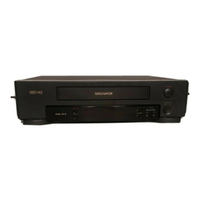
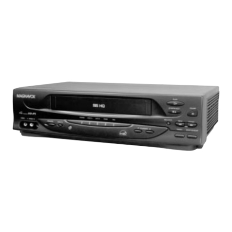
  9. Magnavox VR9622AT01 User manual

Magnavox VR9622AT01 User manual

Other Magnavox VCR System manuals

Magnavox VRB411AT User manual

Magnavox

Magnavox VRB411AT User manual

Magnavox VR402BMG Technical document

Magnavox

Magnavox VR402BMG Technical document

Magnavox VR401BMG User manual

Magnavox

Magnavox VR401BMG User manual

Magnavox VRC602M User manual

Magnavox

Magnavox VRC602M User manual

Magnavox MSD804 User manual

Magnavox

Magnavox MSD804 User manual

Magnavox MDV2400 User guide

Magnavox

Magnavox MDV2400 User guide

Magnavox VRU262AT User manual

Magnavox

Magnavox VRU262AT User manual

Magnavox VR9262 User manual

Magnavox

Magnavox VR9262 User manual

Magnavox VRU562AT User manual

Magnavox

Magnavox VRU562AT User manual

Magnavox VRU362AT User manual

Magnavox

Magnavox VRU362AT User manual

Magnavox VRU364AT User manual

Magnavox

Magnavox VRU364AT User manual

Magnavox VRT245AT User manual

Magnavox

Magnavox VRT245AT User manual

Magnavox VRC202MG User manual

Magnavox

Magnavox VRC202MG User manual

Magnavox VR602BMG User manual

Magnavox

Magnavox VR602BMG User manual

Magnavox VRT245A User manual

Magnavox

Magnavox VRT245A User manual

Magnavox VRU662AT User manual

Magnavox

Magnavox VRU662AT User manual

Magnavox VR402BMG User manual

Magnavox

Magnavox VR402BMG User manual

Magnavox VRT344 User manual

Magnavox

Magnavox VRT344 User manual

Magnavox MVR650MG - Vcr Hifi User manual

Magnavox

Magnavox MVR650MG - Vcr Hifi User manual

Magnavox MVR430MG - Vcr Mono User manual

Magnavox

Magnavox MVR430MG - Vcr Mono User manual

Magnavox VR601BMG User manual

Magnavox

Magnavox VR601BMG User manual

Magnavox VRU242AT User manual

Magnavox

Magnavox VRU242AT User manual

Magnavox VRS960AT01 User manual

Magnavox

Magnavox VRS960AT01 User manual

Magnavox VRX562AT99 User manual

Magnavox

Magnavox VRX562AT99 User manual

Popular VCR System manuals by other brands

RCA VR678HF user guide

RCA

RCA VR678HF user guide

Zenith VRL4270HF Operating guide & warranty

Zenith

Zenith VRL4270HF Operating guide & warranty

Akai VS-606EA Operator's manual

Akai

Akai VS-606EA Operator's manual

Panasonic NV-SJ412EE operating instructions

Panasonic

Panasonic NV-SJ412EE operating instructions

FUNAI 27C-450 Service manual

FUNAI

FUNAI 27C-450 Service manual

Sanyo VHR-M262EV Service manual

Sanyo

Sanyo VHR-M262EV Service manual

Sony SLV-X37 operating instructions

Sony

Sony SLV-X37 operating instructions

JVC SR-VS20U - Dual Format S-vhs/minidv Recorder instructions

JVC

JVC SR-VS20U - Dual Format S-vhs/minidv Recorder instructions

Grundig GV 7400 EURO Service manual

Grundig

Grundig GV 7400 EURO Service manual

Zenith VCM321 Installation and operating guide

Zenith

Zenith VCM321 Installation and operating guide

JVC HR-A43U, HR-A63U instructions

JVC

JVC HR-A43U, HR-A63U instructions

Aiwa VX-S135U operating instructions

Aiwa

Aiwa VX-S135U operating instructions

RCA VR725HF user guide

RCA

RCA VR725HF user guide

JVC 0703-AH-PJ-BJ instruction manual

JVC

JVC 0703-AH-PJ-BJ instruction manual

TruTech ZV450TT8 owner's manual

TruTech

TruTech ZV450TT8 owner's manual

JVC HR-DVS1EK instructions

JVC

JVC HR-DVS1EK instructions

Sensory Science DDV2120 user guide

Sensory Science

Sensory Science DDV2120 user guide

JVC HR-VP78U instructions

JVC

JVC HR-VP78U instructions

manuals.online logo
manuals.online logoBrands
  • About & Mission
  • Contact us
  • Privacy Policy
  • Terms and Conditions

Copyright 2025 Manuals.Online. All Rights Reserved.

MVQTSI 236
| 851 330001
.::ii-:r .. i:r.,,. ,:t:i.r .r- :
Check to be sure the following items are packed with your VCR.
These additional accessories are available to you from Magnavox or your local Magnavox dealer.
. Color Video Camera or VHS Movie Maker
o AC Adaptor (Camera Power Supply)
o 112" Yideo Cassette Tape
This video recorder equipped with the HQ System is compatible with existing VHS equipment.
N.A.P. CONSUMER ELECTRONICS CORP. recommends that you use only cassette tapes which have been
tested and inspected for use in 2, 4, 6 and 8 hour video cassette recorders, and which are labeled with the
IVFS mark.
The use of tapes which have not been tested and inspected tor 2, 4,6 and 8 hour recorders may result in poor
picture quality, excess deposits on the VIDEO head, which may not be covered by the Warranty if damage occurs.
These accessories are provided to help you use or set up your VCR.
1pc. Wireless Remote
Control and 2 "AA"
batterles
(vsos0555)
L
1pc. VHF Connecting
Cable (VSQS0217)
75 OHM
1pc. Twin-Lead Cable
(vJA0102) 300 oHM
.t pc. 300 ohrn - 75 ohm
Transformer (VSOS0513
or VSQSOS19)
The serial number of this product may be found on
the back of the unit. No others have the same serial
number as yours. You should record the number
and other vital information here and retain this book
as a permanent record of your purchase to aid
identification in case of theft.
Dateof Perrchase jg l)ec. tg"1
Dealer Purchased From t-i r o A t .s
Model No. VR9622ATO1
Serial No. -5- 5 .f :3 -{6 oo
Dealer Address =<e,,.,,, f ;ty /,1a rl Li.;1f.,, ,"1 ,-:l
Dealer Phone No. 1,., I ^'
To prevent electric shock do not use this (polarized)
plug with an extension cord, receptacle or other ouflet unless
the blades can be {ully inserted to prevent blade exposure.
r Afin de pr6venir tout risque des chocs
6lectriques, ne pas utiliser de rallonge avec cette liche polaris6e
De plus, ne pas brancher cette fiche dans quelque prise de
courant que ce soit si les lames ne peuvent 6tre ins6r6es a
fond sans laisser de partie d6couverte.
AffiA
CAUTION TO BEDUCE THE RISK OF ELECTR1C SHOCK
DO NOT FEMOVE COVER (CF BACK)
NO USEB-SEBVCEABLE PAFTS NSIDE
REFEB SEBVIC]NG TO QUAL FIED SEBVICE PEFSONNF A
A
,/o\
This symbol warns the user that uninsulated voltage
within the unit may have sufficient magnitude to cause
electric shock. Therefore, it is dangerous to make any
kind of contact with any inside part of this unit.
This symbol alerts the user that important literature
concerning the operation and maintenance of this unit
has been included. Therefore, it should be read
carefully in order to avoid any problems.
wtr
ffi &ffituffi #ffi ffiffiffiYffiffiWffi VR9622ATO1
EMYffiffiMEJffiY6ffiM
We are pleased to introduce to you one of the most
sophisticated viewing and enteftainment products
available today.
This manual is designed to get you started quickly so
you can begin to enjoy the world of video as soon as
possible. On the next page you will find the basic steps
for setting up your VCR to view tapes on your TV.
Later you may select a signal connection from the
"ANTENNA CONNECTIONS" which wiil enabte you to
make VCR recordings. This manual is simply arranged
with all the information you may need for any particular
situation. Check through this table of contents, then the
4-5-and-6-:Any
to the controls
Fffi&YUffi€$
o HQ (High Quality) System
. Front Loading
. Up to Eight-hour recording
o Frequency Synthesizer Tuning
Page 41
Page 33
o On Screen Display . .. Page 19
o Cable-Capable . . Page 10
. lndicator Panel . Page 5
o Special effects playback page 13
Fast Search
Double Speed Playback
Still Picture
Frame Advance
Stow-Motion
. One Touch Recording with
AutomaticPowerOFF . ..... page21
. Unattended (Timer) Recording page 28
e Watch one channel while
recording another page 18
o Auto Power/Eject page 3
o Wireless Remote Control . . . . page 6
G&TT$ruG T# K$**W Y*{jffi V*ffi
Accessories .......1
Table Of Contents ........2
VCR To TV System Preparations ........ 3
$tPdpLffi pL&v&&eK $?Ep$
B&S[C *pmmAT'&NS
To Playback A Pre-recorded Tape
Special Effects Playback
To Record A TV Program ....
OSDlnformation...
One Touch Recording
Timer Recording
Following The Program Guide .
On Screen Display
&mpt?t0&reL *pFm&Tt&r*
CameraRecording .......31
Re-Becording .....32
G Cfi€ Kffi ,&,L l$\t F*ffi &#&T6*h,
Wireless Remote Battery lnstallation ....20
Useful Features For Recording . . . 30 .
Details ....35,,rirr:';l
',i..tr. _
Notes On Operations .....39 11,,,,,,,.
A Word About The Cassette . . . . . 41 ,,::'::'.
BeforeBequestingService ......42
Warranty 44 1,';;,:,',,,:;,,
Specifications ... BackCover l
N*T*; These "KEYS" will identify sections in the
manual relating to the functions listed above.
can be found in alphabetical orcler on pages BS-38.
Keep this manual handy to serve as a quick guide to
the video features on your new VCR.
;h,
-*
&NTffi N&g& eSF€g{€STI&N$
pffiffip&ffitr',G YHm v*m F&ffi mffi*&ms$ru*
&s-iqJsrMr${T$
-2-
Wmre -s# Yw #wffiyffiffi ffiffiffiffieffiew#ffiffiffi
Before Playback, make the one-time preparations A and B below.
ffi&s+* w*$q ?* TV **ruffiffi*rt*$s
This is the only connection you need for Playback.
FL&Yffi&*S #*ruruf;*Tl*&
Back of VCR TypE A (75 ohm VHF)
VHF Connecting Cable (supplied)
OR TYPE B (300 ohm VHF)
Back of TV
-Connect to VHF
TV terminal
-Connect to VHF
- -TV terminals
See ANTENNA CONNECTIONS
for additional hook-up details.
ANTE\
oVHF/
(our
rUHFI
(our
.UHF/
(rN FF
rVHF I
(rN FF
Your VCR must control one TV channel permanently
just as a TV broadcast station does. To decide which
channel to use, select either channel 3 or 4 with the
Channel 3/4 switch on the back of the VCR. To avoid
local interference, the channel 3/4 switch position
you choose should correspond to the number of the
TV channel that is not normally broadcast in your
area. lf you have cable TV, select the channel that
provides the best reception. You can still watch your
favorite channels, see page 15 for normal broadcast
channel reception.
&{*1$,i T* }ruSffiffiT iiru* ffiffiM#Vffi & Vi*ffi* *&S$ffiT?ffi
o Be sure the VCR is plugged into a live AC outlet.
:a rr$cia u vi*€{l rr.*$fril*l
1. Hold the cassette, window side up, with the arrow
pointing away from you.
2. Gently push the cassette in until the pull of the
VCR loading mechanism takes the cassette into
position.
Auto Power
. ffre frcn power will come on and stay on.
"l-l l{*r-:*lt * t;l:5*11t':
1. Press the EJECT Button.
Auto Eject
o lf the VCR Power is OFF, a cassette can still
be ejected by pressing the EJECT Button.
2. Remove the cassette.
Vario, s
o POWE
o HECO|
(Two
o STOP
SPEC .
PLAY3
e PAUS]
oREWS
o SLOW
o SLOW
ON S'
o FUNC'
oOSD E
o HELP
o PROG
oDAYE
r STAR]
(uP D(
r LENGI
(uP D(
r ONE T(
(o.T F
CHANNEL
EJECT Button
-3-
Wep*ffispyfr@ffi &s s#Feyffi#Ls VR9622ATO1
See "DETAILS" section for more information on each control, paqe 35.
COUNTER
tEOUNTER.BUiToN
r'HESET:BUTTON
c MEMOBY:BU:ITO,N
HANNEL MEMORY
r,*NTEIrtt.ltA SVSTTEM. SEEEg?
BUrroN
1:,Qfffi MEli,toRY
oADD/DELETE BUTTON
o CASSETTE COMPARTMENT
. EJECT BUTTON
INDICATOR PANEL
TAPE.SPEED SELECTOR
(sP/LPlSLP)
CLOCK ADJUSTMENT
TRACKING CONTROL
(uP/DOWN)
.cLogK.EUTrOl;,, .:. . :.'
SELEcT, guT. T,.i],N..... .
$ET,BU,TToNS:iUp.hiOW,ur
TAPE MOTIOI
" <tt[[!t> ,,
o CASSETTE.IN
INDICATOR "
r PLAY IND|CA-
r RECORD INDI
r VCR/TV tNDtC
These symbols ar
mode or operatio
displayed on TV
:'., .sToF. .l
-
!l!Illtt
*f**Tfi; ln playbar
function fr
ml{fffi,lrJffi
o SPEED INDIC
r TIMER INDICi
WIRELESS REMOTE
SENSOR
POWER BUTTON
VCR/TV SELECTOR
CHANNEL UP/DOWN KEYS
This display indica
isie#if
. SPEED INDICATOR (SP" #LP" !!SLP"
. TIMER INDICATOR
- TAPE MOTION DISPLAY
" <ltt[lll> "
. CASSETTE-IN ,,,,
INDICATOR " 6f,
CATV INDICATOR
CHANNEL DISPLAY
CLOCK/TAPE COUNTER
DISPLAY
. PLAY INDICATOR
. RECORD INDICATOR/
. VCR/TV INDICATOR "VC
ANTE'-
rVHFA
(our 1
.UHFA
(ouT'l
.UHFA
(rN FR(
r VHF AJ
(lN FR(
Vario u s
o POWEi
o RECORI
(TWO B
o STOP B
SPEC I
PLAYB:
o PAUSE
o REW SE
o SLOIVJ
. SLOW T
ON SC=
o FUNCTI
o OSD Bt
r HELP ts
r PROGR.
o DAY BL
o START
(uP DCI!
o LENGTT
(uP DO1
. ONE TOI
(o.T B l
MEMORY INDICATOR *M"
These symbols and their combinations appear constantly or flash on the lndicator panel to indicate the current
mode or operation of the VCR. Take a look at the chart below. The current indications will be momentaril!,
displayed on TV screen for a quick glance when you press the Operation Button (see page 19).
This display indicates at a glance the tape direction and its speed. See the chafi below.
ln playback mode, one press of the FFlSEARCH or REWIND/SEARCH Buttons locks in the sea._-
function for viewing, press again to return to playback.
trl> \,sLP So-[ib-.ru
iI lim_-lTh Fr Sa
vgR riT E.n
STOP EJECT PLAY REC REC PAUSE STILL DEW
llllllll -IiltIrrI -
oz i \- PLAY -,rlgonrno>
mmPLAY
----\-----
-DEW-
tl'
FUNCTION DISPLAY READOUT ___YE_
The speed of the
sequentially
flashing symbols
on display will
increase or
decrease
depending on :h:
tape speed,
FF
REC
Search )) -
Double Speed Playback
Frame Advance
Slow Motion
!!ffiffi !nr!@ II:ifigfrJ#J'i iJl,T
&rsd-(s:&1.;.,j*.r*jza's*i$, right'
REW
Search {{* .##nInlSHnn This disptay wiil tight up
"sil L_r Lr L_r Lr T1:1..s L_.r u sequentially from right to
.i*ts,*.,'t;r:rmsr'*srr*:, left.
-5-
\
CONNECTIONS WITH
OTHER COMPONENTS
. VIDEO OUTPUT CONNECTOR
.. VIDEO INPUT CONNECTOR
'. AUDIO INPUT CONNECTOR
. AUDIO OUTPUT CONNECTOR
VR9622AT01
Various VCR function controls are conveniently available with your Wireless Remote Control
ANTENNA CONNECTION
o VHF ANTENNA OUTPUT TERMINAL.
(ouT To TV SET)
o UHF ANTENNA OUTPUT TERMINALS
(ouT To TV SET)
o UHF ANTENNA INPUT TERMINALS
(rN FROM ANTENNA)
r VHF ANTENNA INPUT TERMINAL ..-- .
(rN FROM ANTENNA)
o POWER BUTTON
o RECORD BUTTONS
(TWO BUTTON ENTRY)
r STOP BUTTON
SPECIAL EFFECTS
PLAYBACK
r PAUSE/STILL BUTTON - -
r REWSEARCH << BUTTON
o SLOW-MOTION BUTTONS .
o SLOW TRACK]NG CONTROL -
ON SCREEN DISPLAY
r FUNCTION BUTTON
. OSD BUTTON*
o HELP BUTTON*
o PROGRAM BUTTON*
o DAY BUTTON*
o START BUTTONS*
(uP/DOWN)
o LENGTH BUTTONS*
(uP/DOWN)
o ONE TOUCH RECORD
(o.T.R.) BUTTONx See page 20 for
:r@-
E =-l =r
ffit__=
r--E
< FEIV SEAACH.F F, E '
EE
-o.w-!-- sLow - uP
E=E=
i;idi -rartilna =
I_FT_
FFa,C
or.@er
,-qs}_ PFqIi STAPI
5Et: DA- L:NarH
r- E F=TT-
- :E lm\rAt[isEF.
=E=
---.
* WITH PROGRAM
SWITCH ON
Battery Replacement caution.
-6-
. CHANNEL 3/4 SWITCH
o AC POWER CORD
CHANNEL SELECTION
. CHANNEL UP/DOWN KEYS
r NUMERICAL KEYS (0, 1,2,3,
4, 5,6,7, g, and g)
r VCR/TV SELECTOR BUTTON
-' o PLAY BUTTON
SPECIAL EFFECTS
PLAYBACK
r FBAME ADVANCE BUTTON
r FAST FORWARDiSEARCH
>> BUTTON
o DOUBLE SPEED (X2) PLAY
BUTTON
o PROGRAM SWITCH
UNATTENDED (TIMER)
RECORDING
o OSD BUTTON*
o PROGRAM BUTTON*
o DAY BUTTONT
o START BUTTONS (UP/DOWN)'
o LENGTH BUTTONS (UP/DOWN)E
o NORMAL BUTTON,
o TIMER BUTTON "
o CHANNEL UP/DOWN KEYS
ffi
ffiesff# ##ffiffiffiffiY&ffireffi
* 83ffi r*YE Fre&Y'*r{ rHffi ft,{s
The illustrations and descriptions below show the different names and types of connectors and terminals that
may be used to help you to better understand the terminology used in this manual.
&f'd?ffi &d f\8& SS g{ f* ffi *TE * SdS
Before you purchased your VCR you probably had an antenna or cable system connected to your TV set. Before
removing whichever system is connected to your TV, pay particular attention to the type of connection you have
on the back of the TV.
For complete playback and recording capabilities on the VCR you must make the proper connection. To record
TV programs on the VCR you must have a signal source present, either from an antenna or cable system. This
is accomplished by connecting the signal source to the VCR and connecting the VCR to your TV.
You can:
* Watch a program being recorded by the VCR.
* Watch a program with the VCR OFF (the signal will be passed through the VCFI to the TV).
* Record one channel while watching another.
choose from the illustrations below which antenna system is connected to your TV.
A
N
T
E
N
N
A
T
o
V
c
R
Terminals
N@
300 ohm
Cable
Twin lead
(300 ohm)
Connectors
300
ohm
Adapters
300-75 ohm
75-300 ohm
@
75 ohm
Coaxial
cable
(75 ohm
shielded)
(Screw-on type)
F-type
r]IlTIT.rrlH (Stip-on type)
Present VHF Antenna Connection Present UHF Antenna Connection
OB
I
1 Remove the VHF signal source 1 Remove the VHF signal source
from the antenna connections on from the antenna connections on
the back of the TV. the back of the TV.
1 Remove the UHF signal source
from the antenna connections.
2 Attach the signal source to the
back of the VCR terminal marked
..IN FROM ANT.",
2 Attach the two leads onto the teminals
of the 300-75 ohm adapter (supplied).
Plug the end of the adapter into the VHF
lerminal marked "lN FROM ANT.".
a@
W=-"@
2 Attach the two leads to the UHF
terminals marked "lN FROM ANT.".
-7-
VR9622ATO1
v
c
R
T
o
T
V
3 Attach the UHF antenna twin lead
wires (supplied) to the terminal
marked "OUT TO TV" on the VCR.
Connect the other end to the UHF
terminals on the TV.*
}}oQr ro fi
@@
@O
'N fFou nu
)J
3 Attach the VHF Connecting Cable (supplied) to the terminal marked
"OUT TO TV" on the back of the VCR. Connect the other end of the VHF
Connecting Cable to the back of the TV according to the type of terminal
on the back of the TV.
* lf you receive only UHF channels, you must also add one of the two VHF connections between VCFI and
TV described above. This connection is necessary to view tapes in playback and to monitor recording.
(srDE)
ruTV
l_t tr lf your TV has a single VHF/UHF lnput you will
need to combine the two leads going from the
VCR to the TV, use a Combiner (Part No.
7051090001) which can be obtained from your
dealer or nearest NAPCEC Parts Center.
Combiner
-8-
,&
. sSgffi,-ffi. ffi$ g $t: *';' l; r..'i i r lN.€
*tE#.i.$e€-i.*nnLEffi::SEtr ;t+*:*:Ei{S:{.+tj!}E}*SJi:
**F,i Xitr l{Ttr {q rmf **& j1{ tr*S l"H ffi ,* *}.
lf your cable service supplies you with a converter box, you can use the basic connection shown here. lf your
cable system is different, see "ALTERNATE CABLE CONNECTIONS".
l',ri.r:.1i,; Channel selection must be made at the cable company conveder box. Therefore, the VCR's remote control
channel selection feature cannot be used. Unattended recording is limited to one channel at a time, and you
cannot view any channel other than the one you are recording.
The following feature will operate with this connection.
Record and view any channel including scrambled (if available).
Y* frfi**ft# &f{$} v'Hw e $*fr&Mslr*iuN5*&&wmLfr* *fiANru[L
1. Press the VCR/TV Selector Button located on the front of VCR so the lndicator displays "VCR".
2. Set TV channel selector to the output channel of the VCR.
3. Set VCR channel selector to the output channel of the Cable Converter Box (e.g. CH3).
4. Select channel to be recorded at the Cable Converter Box.
T* W&TC*4 TV {}Si-r'S Ti{S V*!q *r:r}
'l . Set TV channel selector to the output channel of the Cable Converter Box.
2. Select the desired channel on cable converter channel selector.
l',1,:;' 1.,:,, i,r.:' 1..: til''l tr l;rll:rill':l t l'l t:;'l ; i i,rl :
This reminder is provided to call the CATV system installer's attention to Article 820-22 of the NEC in USA
(and to the Canadian Electrical Code in Canada) that provides guidelines for proper grounding and, in particular,
specifies that the cable ground shall be connected to the grounding system of the building, as close to the
point of cable entry as practical.
CATV (cable)
-9-