Magnum Dimensions ACLD-40 User manual

ACLD-40
AC Load Diversion Controller - 4.0kW
Owner’s Manual

© 2015 Sensata Technologies Page i
Thank you from all of us at Sensata Technologies for purchasing this ACLD-40 controller. The
ACLD-40 (also know as the ACLD) is a product under the Magnum-Dimensions brand from Sensata
Technologies. We understand that you have many purchasing options in the marketplace, and we
are pleased that you have decided on this product. This ACLD was proudly assembled and tested
in the United States at our facility in Everett, Washington.
At Sensata, we are committed to providing you with quality products and services, and hope that
your experience with us is pleasant and professional.
Disclaimer of Liability
The use of this manual and the conditions or methods of installation, operation, use and maintenance
of the ACLD controller is beyond the control of Sensata Technologies. Therefore, this company does
not assume responsibility and expressly disclaims liability for loss, damage, or expense whether
direct, indirect, consequential or incidental that may arise out of or be any way connected with
such installation, operation, use, or maintenance.
Due to continuous improvements and product updates, the images shown in this manual may not
exactly match the unit purchased.
Restrictions on Use
The ACLD may only be used in life support devices and systems with the express written approval
of Sensata Technologies. Failure of this load diversion controller can reasonably be expected to
cause failure of that life support device or system, or to affect the safety or effectiveness of that
device or system. If the ACLD fails, it is reasonable to assume the health of the user or other
persons may be endangered.
Copyright Notice
Copyright © 2015 by Sensata Technologies. All rights reserved. Permission to copy, distribute, and/
or modify this document is prohibited without express written permission from Sensata Technologies.
Document Information
Description – ACLD-40 Owner’s Manual
Part Number and Revision – 64-0062 Rev A
Date Published – February 2015
This manual is printed without color for cost savings. However, this entire manual is available
for download—with many of the figures available in color—under the Document Library tab at
www.Magnum-Dimensions.com.
Contact Information
For Magnum-Dimensions Products:
Sensata Technologies
2211 West Casino Rd.
Everett, WA 98204
Phone: 425-353-8833
Fax: 425-353-8390
Web: www.Magnum-Dimensions.com
Record the ACLD’s serial number in case you need to provide this information in the future.
Model: Serial Number:
ACLD-40 TA

Safety Information
Page ii
IMPORTANT PRODUCT SAFETY INSTRUCTIONS
SAVE THESE INSTRUCTIONS
THIS MANUAL CONTAINS IMPORTANT INSTRUCTIONS FOR THE ACLD-40 CONTROLLER THAT SHALL
BE FOLLOWED DURING THE INSTALLATION AND OPERATION OF THIS PRODUCT. Before using
the ACLD, read all instructions and cautionary markings. Also, be sure to follow the instructions
provided for each component of the system. Do not perform any installation or service described
in this owner’s manual unless properly trained and capable. Incorrect installation or service may
result in the risk of electric shock, fire, or other safety hazard.
Safety Symbols
The following safety symbols have been placed throughout this manual to indicate dangerous and
important safety instructions.
WARNING: This symbol indicates that failure to take a specified action could result in
physical harm to the user.
CAUTION: This symbol indicates that failure to take a specified action could result in
damage to the equipment.
Info: This symbol indicates information that emphasizes or supplements important
points of the main text.
Safety Precautions
• All electrical work must be performed in accordance with local and national electrical codes.
• This product is designed for indoor/compartment installation. It must not be exposed to rain,
snow, moisture, or liquids of any type.
• Use insulated tools to reduce the chance of electrical shock or accidental short circuits.
• There are no user-serviceable parts contained in this product.
• This unit is provided with integral protection against overloads.
• Use Class 1 wiring methods for field wiring connections to terminals of a Class 2 circuit.
• Listed or labeled equipment shall be installed and used in accordance with any instructions
included in the listing or labeling.
• Always verify proper wiring prior to turning on the ACLD.
• Use only copper wires with a minimum temperature rating of 75°C (167°F).
• AC wiring must be no less than #10 AWG (5.3 mm2) gauge copper wire.
• Torque all AC wiring connections to the required values.
• The ACLD must be properly mounted, see Section 2.3 “Mounting the ACLD” in this manual.
• Protection for the AC output wiring against overcurrent is not included in the ACLD and must
be provided as part of the system installation. Refer to Section 2.8 “Wiring the ACLD” for more
information.
• The AC output neutral conductor is not connected (bonded) to the ACLD chassis. Both the input
and output conductors are isolated from the ACLD chassis. System grounding, if required, is
the responsibility of the system installer and must comply with local and national electrical
codes and standards.

Safety Information
© 2015 Sensata Technologies Page iii
CONSIGNES DE SÉCURITÉ IMPORTANTES
CONSERVER CES INSTRUCTIONS
CE MANUEL CONTIENT DES INSTRUCTIONS IMPORTANTES POUR LE CONTRÔLEUR ACLD-40 AU
COURS DE L’INSTALLATION ET FONCTIONNEMENT DU PRODUCT. Before utilisant le ACLD, lire
toutes les instructions et mises en garde. Aussi, assurez-vous de suivre les instructions fournies
pour chaque composant du système. Ne pas effectuer toute installation ou service décrit dans le
manuel du propriétaire, à moins bien formé et capable. Mauvaise installation ou entretien peuvent
entraîner des risques de choc électrique, d’incendie ou autre danger pour la sécurité.
Symboles de sécurité
Les symboles de sécurité suivants ont été placéstout au long de ce manuel pour indiquer des
conditions dangereuses et les consignes de sécurité importantes.
AVERTISSEMENT: Ce symbole indique que le défaut de prendre une action spécifiée
pourraitcauser des dommages physiques à l’utilisateur.
ATTENTION: Ce symbole indique que le défaut de prendre une action spécifiée peut
entraîner des dommages à l’équipement.
Info: Ce symbole indique une information qui met l’accent ou des suppléments points
importants du texte principal.
Consignes de sécurité
• Tous les travaux électriques doivent être effectués en conformité avec les codes locaux et
nationaux électriques.
• Ce produit est conçu pour l’installation / du compartiment intérieur. Il ne doit pas être exposé
à la pluie, la neige, l’humidité ou des liquides de tout type.
• Utiliser des outils isolés pour réduire le risque de choc électrique ou courts-circuits accidentels.
• Il n’y a pas réparable par l’utilisateur contenues dans ce produit.
• Cet appareil est fourni avec une protection intégrale contre les surcharges.
• Utiliser des méthodes de câblage Classe 1 pour les connexions de câblage sur le terrain aux
bornes d’un circuit de Classe 2.
• Coté ou étiquetés équipement doit être installé et utilisé conformément aux instructions
figurant dans la liste ou l’étiquetage.
• Toujours vérifier le câblage avant de mettre sur le ACLD.
• Utilisez des fils de cuivre seulement avec une cote de température minimale de 75°C (167°F).
• AC câblage ne doit pas être inférieure à #10 AWG (5.3 mm2) de cuivre de calibre.
• Serrer toutes les connexions de câblage ca aux valeurs requises.
• Le ACLD doit être correctement monté, voir la Section 2.3 “Montage du ACLD” dans ce manuel.
• Protection pour le câblage de sortie AC contre les surintensités n’est pas inclus dans le ACLD
et doivent être fournis dans le cadre de l’installation du système. Reportez-vous à la Section
2.8 “Câblage du ACLD “ pour plus d’informations .
• Le conducteur de sortie CA neutre n’est pas connecté (collé) sur le châssis ACLD. À la fois
l’entrée et la sortie des conducteurs sont isolés du châssis ACLD. Sol, si nécessaire, est
de la responsabilité de l’installateur du système et doit être conforme aux codes locaux et
nationaux et des normes électriques.

Page iv © 2015 Sensata Technologies
Table of Contents
1.0 Introduction............................................................................. 1
1.1 What is an AC Load Diversion Controller (ACLD)?...................................... 1
1.2 What is an AC Coupled system, and why do I need an ACLD? ..................... 1
1.3 How an AC Coupled System Works.......................................................... 2
1.4 Battery Regulation Methods ................................................................... 4
1.5 ACLD Features and Benefits ................................................................... 6
2.0 Installation .............................................................................. 8
2.1 Pre-Installation .................................................................................... 8
2.2 Locating the ACLD Controller................................................................ 10
2.3 Mounting the ACLD Controller............................................................... 11
2.4 General Wiring Requirements ............................................................... 13
2.5 Torque Requirements .......................................................................... 14
2.6 ACLD Terminal Block Connections ......................................................... 15
2.7 Electrical System Wiring Diagrams ........................................................ 15
2.8 Wiring the ACLD ................................................................................. 18
2.9 ACLD Load Requirements..................................................................... 19
2.10 Connecting the ACLD to a MS-PAE Series Inverter................................... 21
2.11 Using a Remote Control with the ACLD Controller.................................... 22
3.0 Operation............................................................................... 23
3.1 ACLD Operation.................................................................................. 23
3.2 Three-Stage Regulation ....................................................................... 25
3.3 Operation Scenarios - Utility Connected ................................................. 26
3.4 Power Flow Scenarios - Utility Not Connected ......................................... 27
3.5 Power Switch Operation....................................................................... 30
3.6 Inverter Fan Operation ........................................................................ 30
3.7 Operating Modes ................................................................................ 31
3.8 Monitoring the ACLD Controller with a ME-ARC Remote Display................. 31
3.9 ACLD Startup ..................................................................................... 32
4.0 Troubleshooting..................................................................... 33
Appendix A – Specifications and Optional Equipment..................... 35
A-1 ACLD-40 Load Diversion Controller Specifications.................................... 35
A-2 Regulatory Compliance ........................................................................ 36
A-3 Optional Equipment and Accessories...................................................... 36
Appendix B – Warranty and Service .............................................. 37
B-1 Limited Warranty ................................................................................ 37
B-2 How to Receive Repair Service.............................................................. 37

© 2015 Sensata Technologies Page v
List of Figures
Figure 1-1, ACLD Inactive (Utility Power Available)............................................................ 2
Figure 1-2, ACLD Active (Utility Power NOT Available)........................................................ 3
Figure 1-3, Intake Fan, Status LED, Connection Ports, and Knockouts.................................. 6
Figure 1-4, ON/OFF Power Switch, Info Label and Exhaust Vents......................................... 7
Figure 1-5, Wiring Access Cover ..................................................................................... 7
Figure 2-1, Simplified ACLD System................................................................................ 8
Figure 2-2, Removing Knockouts ...................................................................................10
Figure 2-3, Approved Mounting Positions ........................................................................11
Figure 2-4, ACLD Dimensions and Side Reference ............................................................12
Figure 2-5, ACLD Terminal Block....................................................................................15
Figure 2-6, ACLD System Wiring....................................................................................16
Figure 2-7, AC Wiring from Inverter to ACLD...................................................................17
Figure 2-8, ACLD to Inverter Communications Cable Connection ........................................21
Figure 2-9, ACLD/NETWORK Communication Cable ..........................................................21
Figure 3-1, Automatic 3-Stage Graph .............................................................................25
Figure 3-2, Utility Connected - Surplus Power Fed to the Utility Grid ...................................26
Figure 3-3, Utility Connected - Additional Power Provided by the Utility Grid ........................26
Figure 3-4, Utility not Connected - RE Powers Critical Loads ..............................................27
Figure 3-5, Utility not Connected - Additional Power Provided to Critical Loads .....................27
Figure 3-6, Utility not Connected - Excess Current Charging Battery Bank ...........................28
Figure 3-7, Utility not Connected - Diverting some Power to Primary Load...........................28
Figure 3-8, Utility not Connected - Diverting all Power to Primary Load ...............................29
Figure 3-9, Utility not Connected - Diverting Power to Secondary Load ...............................29
Figure 3-10, Power Switch ............................................................................................30
Figure 3-11, Checking Load Resistance...........................................................................33
List of Tables
Table 2-1, Torque Values for Ground Busbar ....................................................................14
Table 2-2, Torque Values for the AC Terminal Blocks .........................................................14
Table 3-1, LED Blinks to Fault Condition..........................................................................32

Page vi © 2015 Sensata Technologies

Page 1
© 2015 Sensata Technologies
Introduction
1.0 Introduction
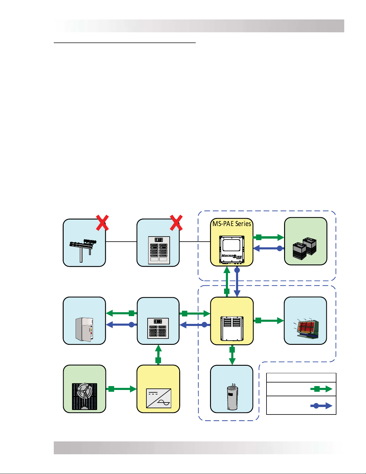
Congratulations on your purchase of the ACLD-40 (AC Load Diversion - 4.0kW) controller. The
ACLD-40 (also know as the ACLD) is designed to be used in an AC coupled system—networked
with a MS-PAE Series1inverter—to provide three-stage battery charging and to divert any excess
power to a resistive load.
The ACLD-40 controller includes the following features:
• Automatic three-stage battery regulation (with adjustable voltage and charging parameters).
• Controls up to 4000 watts of excess power to prevent battery overcharge.
• Automatic battery temperature compensation—provides optimum charging even during
extreme temperature changes (when using the inverter’s Battery Temperature Sensor).
• A networked diversion device—using inverter and network ports.
• ON/OFF mounted switch with status/fault indicator LED; operation and power information
is provided when using the inverter’s remote.
• Designed to work with MS-PAE Series inverters to prevent battery overcharging.
• Diversion load is isolated from in-home AC loads and receives PWM (Pulse Width Modulation)
voltage—prevents AC line disturbance by providing smooth transition when regulating.
• Allows the use of resistive AC household loads (i.e., water heater tanks) instead of expensive
and hard to find DC loads to divert excess current.
• Does not require additional/external sensors to monitor battery inverter output current,
battery voltage, or battery type.
1.1 What is an AC Load Diversion Controller (ACLD)?
The basic operating concept of an AC or DC diversion controller is quite simple. Monitor the battery
bank, and if an energy source (e.g. solar panel, wind generator, etc.) should cause the battery
to rise to a predetermined voltage level, connect a diversion load of sufficient size to prevent the
battery from being overcharged. By diverting the unused energy that your solar panel or wind
generator is producing, you can make use of it—such as heating a hot water or heating a room.
The ACLD-40 is an AC load diversion controller that maximizes the use of onsite-generated power
(i.e., renewable energy) by diverting any excess energy to resistive loads on the AC side. By
diverting the excess current on the AC side and not on the DC side (through the battery-based
inverter), there is less strain on the battery-based inverter. Also, since the wiring is on the AC
side, there is less voltage drop, less expensive system wires and diversion loads, and fewer issues
when trying to determine how to size the diversion loads/hardware.
1.2 What is an AC Coupled system, and why do I need an ACLD?
Many homeowners utilize renewable energy (i.e., PV, wind, etc.) by installing a high efficiency,
battery-less, grid-tie inverter (also known as an utility-interactive inverter) to offset their power
consumption from the utility grid. However, these homeowners soon learn that when a utility
power outage occurs, the grid-tie inverter is required to shut down. This can cause considerable
frustration as the homeowner realizes that the critical loads in the home (refrigerator, lights, water
pump, etc.) are no longer powered and all the energy produced by the renewable energy source
is being wasted while the utility power is out.
To overcome some of the disadvantages of a battery-less, grid-tie inverter; homeowners add a
battery-based inverter and batteries to power critical loads during a utility power outage. However,
the generated power from the renewable energy continues to be wasted until the utility power
returns.
1 This manual will specifically refer to the MS-PAE Series to work with the ACLD-40. How-
ever, the ACLD will work with any battery-based inverter that provides a MagNet communications
port and has an output of 230 or 240 VAC (50 or 60 Hz). This means the MS-PAE Series, MS-E
Series, or MS-PE Series inverters will work with the ACLD-40.

© 2015 Sensata TechnologiesPage 2
Introduction
Traditionally, when a battery-based inverter is used, the renewable energy system is connected
or ‘coupled’ to the battery (or DC) side of the inverter. In a DC coupled system, the renewable
energy is wired at a lower voltage to better match the battery bank, and a DC controller is used to
manage the energy to prevent the battery from being overcharged. This type of system is usually
more costly and complex to install because of more components; and because the voltage is lower,
there are more efficiency losses as a whole (when compared to a grid-tie inverter-only system).
However, using a concept known as AC Coupling, a four quadrant (bi-directional) battery-based
inverter (such as Sensata’s MS-PAE Series) can be installed that utilizes the renewable energy to
power the home’s critical loads during a power outage from the AC side. With the addition of a
battery bank, a critical-loads sub-panel, and a diversion controller with load, coupling a MS-PAE
Series inverter on the AC side can be very advantageous. The existing renewable energy system
does not need to be rewired to the DC side, and the high conversion efficiency of the grid-tie
inverter is maintained while the utility power is available.
1.3 How an AC Coupled System Works
Described below is how an AC-Coupled system works when utility power is available, and when
there is an utility power outage.
When utility power is available (see Figure 1-1): Normally, when utility power is available and a
MS-PAE Series inverter is installed, the grid-tie inverter converts the renewable energy to work in
parallel with the utility to power the loads in the home (main-panel and critical loads sub-panel),
charge the battery system, and feed any surplus renewable energy back into the utility grid.
Figure 1-1, ACLD Inactive (Utility Power Available)
Battery Back-up Section
AC Load
(Primary)
ACLD Section
Main
Panel
Utility
Grid Inverter Battery
Bank
Grid-Tie
Inverter
Critical
Loads Sub-
Panel
ACLD-40
Controller
AC Load
(Secondary)
Renewable
Energy Power Flow
Renewable
Energy
Utility Grid

Page 3
© 2015 Sensata Technologies
Introduction
During a utility power outage (see Figure 1-2): When the utility power fails, the grid-tie inverter
disconnects (preventing the use of the renewable energy) and the MS-PAE Series inverter
automatically starts powering the critical loads. However, because the output of the MS-PAE
Series inverter is connected to the same AC bus as the grid-tie inverter and its output waveform
is compatible to the utility’s waveform, the grid-tie inverter re-synchronizes to the AC output
waveform of the MS-PAE Series inverter. After a minimum 5-minute disconnect period, the grid-
tie inverter reconnects and starts inverting all the energy from the renewable energy source just
like it did when it was connected to utility power.
The grid-tie inverter—now reconnected using the AC output waveform of the MS-PAE Series
inverter—converts as much of the available renewable energy as possible. However, during a
utility power interruption, the main panel loads are no longer connected and the utility grid is not
available to export any excess power that is generated. This means there may be more power on
the AC bus than the critical loads can consume, causing current to be pushed back thru the AC
output of the MS-PAE Series inverter into the battery bank. Since this is not the normal path for
the MS-PAE Series inverter to sense incoming current, it is not able to control the battery voltage
(or regulate the current, which requires the inverter to be rated to handle the full power output
of the renewable energy source). If the renewable energy provides more current that the critical
loads can use, there is the possibility that the battery voltage will rise and cause damage to the
battery. If the battery voltage is allowed to rise high enough, a High Battery Voltage fault on
the MS-PAE Series inverter will occur, causing it to turn off; which in turn shuts down the entire
system (i.e., critical loads and grid-tie inverter turn off). To prevent this from happening, there
must be a method of regulating the battery bank and ensuring it is properly charged; this is why
the ACLD-40 is needed.
Figure 1-2, ACLD Active (Utility Power NOT Available)
Battery Back-up Section
AC Load
(Primary)
ACLD Section
Main
Panel
Utility
Grid Inverter Battery
Bank
Grid-Tie
Inverter
Critical
Loads Sub-
Panel
ACLD-40
Controller
Renewable
Energy
Power Flow
Renewable
Energy (RE)
Inverter power
(when RE not
available)
AC Load
(Secondary)

© 2015 Sensata TechnologiesPage 4
Introduction
1.4 Battery Regulation Methods
In an AC-coupled system, there are several methods that are used to regulate the battery voltage,
as described below:
1. AC disconnect driven by DC controlled relays: When the battery voltage rises above a
maximum setpoint, a battery voltage controlled relay is activated to open the AC connection to
the grid-tie inverter. This causes the critical load sub-panel to now be powered from the batteries
through the battery-based inverter. When the battery voltage falls to the low setpoint, the relay
closes and allows the grid-tie inverter to reconnect and begin generating power from the renewable
energy. If the battery voltage rises again, this cycle repeats.
Disadvantages:
• Batteries are cycled, not regulated—does not allow the batteries to be properly charged.
• Generated power from the renewable energy is wasted while the relay is opened.
• The DC relay setpoints must be set much higher than required to ensure the DC relay
doesn’t connect or interfere with normal charging (from the battery-based inverter) and
any sell back voltage settings once the utility power returns.
• No temperature-compensated regulation while charging.
2. DC diversion driven by DC controlled relays: When the battery voltage rises above a
maximum setpoint, a battery voltage controlled relay is used to switch on a dedicated DC diversion
load to consume any excess power. When the battery voltage falls to the low setpoint, the dedicated
diversion load turns off. If the battery voltage rises again, this cycle repeats.
Disadvantages:
• Batteries are cycled, not regulated—does not allow the batteries to be properly charged.
• Difficult to source and size DC diversion loads to absorb the full output of the renewable
energy source.
• The regulation setpoint must be set much higher than required to ensure the diversion load
is not always in “regulation”, and that it doesn’t interfere with normal charging (from the
battery-based inverter) or any sell back voltage settings once the utility power returns.
• Since excess power is regulated on the DC side, the battery-based inverter is required to be
always on, re-converting the renewable energy from AC back to DC where it is diverted—an
extra conversion step creates energy loss and there is an unnecessary use of the inverter.
• No temperature-compensated regulation while charging.
3. DC Diversion Controller off the battery: When the battery voltage rises above a voltage
regulation setpoint, the DC Diversion Controller sends excess current to a dedicated DC diversion
load to maintain the battery voltage. When the battery voltage falls below the regulation setpoint,
current is no longer sent to the dedicated diversion load.
Disadvantages:
• Difficult to source and size DC diversion loads correctly. If the load is too small, it cannot divert
enough power from the source (wind, hydro, etc.), and the battery could be overcharged. If
the diversion load is too large, it will draw more current than the rating of the controller—
causing damage or causing the controller’s protection circuits to open the load.
• Multiple controllers are usually needed even for medium sized renewable energy systems
(i.e., a 4kW/48VDC system requires at least a 70-amp controller).
• The regulation setpoint must be set much higher than required to ensure the diversion load
is not always in “regulation”, and that it doesn’t interfere with normal charging (from the
battery-based inverter) or any sell back voltage settings once the utility power returns.
• Since excess power is regulated on the DC side, the battery-based inverter is required to be
always on, re-converting the renewable energy from AC back to DC where it is diverted—this
extra conversion step creates energy loss and there is an unnecessary use of the inverter.

Page 5
© 2015 Sensata Technologies
Introduction
4. Frequency disturbance/shift from the battery-based inverter: When the battery voltage
rises above a maximum setpoint, a battery-based inverter changes its output frequency to cause
the grid-tie inverter to limit the energy from the renewable energy source to the battery.
Disadvantages:
• Generated power from the renewable energy is limited/wasted during the frequency shift.
• Batteries are cycled, not regulated—does not allow the batteries to get properly charged1.
• The frequency-shift setpoint must be set higher than required to ensure it doesn’t interfere
with normal charging (from the battery-based inverter) or any sell back voltage settings
once the utility power returns1.
• No temperature compensated regulation while charging1.
Note1– May not occur if networked to the grid-tie inverter
5. AC diversion driven by DC controlled relays: A battery voltage controlled relay is used
to switch on a dedicated AC diversion load (i.e., space heater, air conditioner, etc.) to consume
any excess power when the battery voltage rises above a maximum setpoint. When the battery
voltage falls to the low setpoint, the dedicated diversion load turns off. If the battery voltage rises
again, this cycle repeats.
Disadvantages:
• Batteries are cycled, not regulated—does not allow the batteries to be properly charged.
• AC diversion loads must be sized to absorb the full output of the renewable energy source
and configured to always be on (no temperature or thermostat turn-off control).
• AC diversion loads, when activated, can cause enough AC line drop/disturbance to disconnect
the grid-tie inverter—wasting generated energy.
• No temperature compensated regulation while charging.
6. AC Load Diversion Controller (ACLD-40): When the battery voltage rises above a voltage
regulation setpoint, the ACLD-40 begins to send excess current to a dedicated AC diversion load
to maintain the battery voltage. When the battery voltage falls below the regulation setpoint,
current is no longer sent to the dedicated diversion load.
Advantages:
• Batteries are properly charged/regulated - true three-stage charging to batteries during
power outage.
• Easier to source and size AC diversion loads to absorb the full output of the renewable
energy source.
• Primary AC diversion loads can be configured for temperature/thermostat turn-off—primary
loads are not required to always be on.
• AC diversion loads are isolated from the grid-tie inverter’s output to provide a smooth turn-
on transition—prevents the inverter from disconnecting due to AC line drop/disturbance.
• ACLD-40 communicates with the MS-PAE Series inverter, this provides:
o No confusion or interference trying to coordinate the inverter’s and controller’s setpoints
once the utility power returns—controller uses same charge setpoints as the MS-PAE
Series inverter for regulation.
o Temperature compensated regulation while charging—uses temperature sensor readings
from the MS-PAE Series inverter.
o Information on diverted power and the controller’s status can be displayed using a
remote control.
o Knows when grid power returns—ensures the renewable energy is not being diverted
and is available to be fed back to the utility grid.
• Does not require multiple current sensors and devices—all current flow is monitored at the
controller to determine when to divert excess current.
• No AC to DC energy conversion loss when trying to regulate battery voltage—excess power
is regulated on the AC side.

© 2015 Sensata TechnologiesPage 6
Introduction
1.5 ACLD Features and Benefits
The ACLD controller is designed with features that allow easy access to wiring and controls.
The front of the ACLD controller is equipped with the following (refer to Figure 1-3):
1Status LED Indicator – this green LED illuminates to provide operation and fault
information on the ACLD controller.
2Inverter Connection Port (orange) – a RJ11 port for connecting the ACLD controller
to the network port (green) on a the MS-PAE Series inverter.
3Network Connection Port (green) – a RJ11 port for connecting the ACLD controller to
a Network controlled device (i.e., ME-BMK, ME-AGS-N).
4Knockouts – four dual knockouts (½” and ¾”) to accommodate AC wiring access and
routing.
Info: Four additional dual knockouts (½” and ¾”) identical to the ones noted in Item 4
are located on the opposite side (eight dual knockouts total).
5Intake Cooling Fan – an intake fan to pull in air to allow the ACLD controller to operate
continuously at full power.
Figure 1-3, Intake Fan, Status LED, Connection Ports, and Knockouts
S
T
A
T
U
S
L
E
DTO
INVERTER TO
NETWORK
Inverter
Connection Port Network
Connection Port
Intake
Cooling Fan
Dual Knockouts
(½” and ¾”)
54
321
Status LED
Indicator

Page 7
© 2015 Sensata Technologies
Introduction
Figure 1-5, Wiring Access Cover
The left side of the ACLD controller has an access cover that can be removed (Figure 1-5):
9Wiring Access Cover – provides access to the internal AC wiring terminal block and
ground busbar. This terminal block is used to hardwire all AC wiring connections.
Remove the two #6-32 screws to access the AC wiring terminal block.
Figure 1-4, ON/OFF Power Switch, Info Label and Exhaust Vents
The right side of the ACLD controller has an information label, exhaust vents and an ON/OFF
switch (see Figure 1-4):
6Information Label – includes model/serial number information, date of manufacture,
and specifications. See the specifications in Appendix A for more information.
7Exhaust Vents – ventilation openings that allow heated air to be removed by the internal
cooling fan. The exhaust air vents are located on the right side and at the rear of the top
side.
8ON/OFF Power Switch – a power switch that turns the ACLD controller on or off.
9
Wiring
Access
Cover
Information
Label
Exhaust Vents
(on right and top sides) ON/OFF
Power
Switch
8
7
6

© 2015 Sensata TechnologiesPage 8
Installation
2.0 Installation
Read the entire Installation section to determine how best to install the ACLD controller. The more
thorough you plan in the beginning, the better the chances are that the installation will go well.
WARNING: Installations should be performed by qualified personnel, such as a
licensed or certified electrician. It is the installer’s responsibility to determine which
safety codes apply and to ensure that all applicable installation requirements are
followed. Applicable installation codes vary depending on the specific location and
application of the installation.
WARNING: Review the “Important Product Safety Information” on pages ii-v before
any installation.
CAUTION: The ACLD controller weighs 20 lb (9.1 kg), use proper lifting techniques
during installation to prevent personal injury.
Info: The ACLD controller only controls the renewable energy source connected to the
AC side of the system. Any renewable energy source connected to the DC side of the
system must be controlled separately using a DC controller/diversion load.
2.1 Pre-Installation
The simplified system diagram shown in Figure 2-1 should be reviewed to assist you in planning
and designing your installation. This drawing is not intended to override or restrict any national
or local electrical codes. This drawing should not be the determining factor as to whether the
installation is compliant, that is the responsibility of the electrician and the onsite inspector.
MagNet
Comm
ACLD-40
Load
Controller
Output
(to Pri load)
Output
(to Sec load)
Input
(from GTI)
Input
(from BBI)
Grid-Tie
Inverter (GTI)
Main Loads
(Main Panel)
Battery
Bank
MS-PAE Series
-
Battery Based
Inverter (BBI)
Critical Loads
(Sub-Panel)
Grid
Power
Primary
Diversion Load
Mini Magnum
Panel
Secondary
Diversion Load
PV
Power
Figure 2-1, Simplified ACLD System

Page 9
© 2015 Sensata Technologies
Installation
2.1.1 Considerations when Installing the ACLD System
• The ACLD controller is designed to be connected and powered from the AC output of a battery-
based inverter that provides a MagNet communications port and has an output of 230 or 240
VAC (50 or 60 Hz). Normally this would be the MS-PAE Series (MS4024PAE or MS4448PAE),
but can also connect to the MS-E Series and MS-PE Series inverters.
• The continuous power rating of the inverter (MS-PAE Series) must be at least 10% larger than
the maximum power rating of the renewable energy source. Otherwise, the inverter may be
damaged if required to handle current greater than designed.
• During an AC utility outage, some brands of grid-tie inverters are sensitive and disconnect
when powered from battery-based inverters.
• As required by the NEC, a photovoltaic power system (or small wind electric system) employing
a diversion charge controller of regulating the charging of a battery shall be equipped with a
second independent means to prevent overcharging of the battery. The MS-PAE Series inverters
can provide an automatic frequency-shift feature that disconnects the grid-tie inverter when
high voltage is detected on the battery. Note: This frequency-shift feature is enabled by setting
the battery type to ‘custom’ using a remote control, however, this feature should only be used
as a backup—the ACLD-40 should be used as the primary regulation method.
• A diversion load must be connected to the ACLD to prevent over-charge damage to the
inverter’s battery bank. It must be at least 10% larger than the maximum power rating of the
renewable energy source. See Section 2.9 for information on the ACLD load requirements.
• As the AC current is being provided by the grid-tie inverter through the sub-panel (i.e., critical
loads panel) into the ACLD, a 30-amp branch rated circuit breaker must be provided from
the sub-panel to the ACLD. Note: The installation can be made easier by using the MMP-30D
Series enclosure. This enclosure provides the required 30-amp overcurrent circuit protection
between the sub-panel and the ACLD controller.
• The ACLD-40 is limited to 4000 watts continuous and is designed to work with a single MS-
PAE Series pure sinewave inverter that has an output voltage of 240VAC. Note: The ACLD-40
cannot be stacked or combined with another ACLD to handle additional power.
2.1.2 Unpacking and Inspection
Carefully remove the ACLD controller from its shipping container and inspect all contents. Verify
the following items are included:
• The ACLD Controller • 6’ yellow communications cable
• ACLD Owner’s Manual • Access panel with hardware
If items appear to be missing or damaged, contact Sensata. If at all possible, keep your shipping
box to help protect your ACLD controller from damage if it ever needs to be returned for service.
Important: Save your proof-of-purchase as a record of your ownership; it will be required
if the ACLD should require in-warranty repair.
Record the unit’s model and serial number in the front of this manual in case you need to provide
this information in the future. It will probably be much easier to record this information now, rather
than trying to gather it after the unit has been installed.
2.1.3 Required Tools and Materials
Hardware/Materials
• Conduit or strain-reliefs and appropriate fittings • Mounting bolts and lock washers
• Electrical tape • Wire ties
Tools
• Miscellaneous screwdrivers • Pliers • Wire strippers
• Drill and drill bits • Pencil or marker • Multimeter
• Level • 1/2” wrench

© 2015 Sensata TechnologiesPage 10
Installation
2.2 Locating the ACLD Controller
Only install the ACLD controller in a location that meets the following requirements:
Clean and Dry – The controller should not be installed in an area that allows dust, fumes, insects,
or rodents to enter or block the controller’s ventilation openings. This area also must be free from
any risk of condensation, water, or any other liquid that can enter or fall on the controller. Failure
due to any of the above conditions is not covered under warranty.
Info: If the controller is installed in an area where moisture may occur, we recommend
putting silicone dielectric grease compound into the electrical ports (as shown in Figure
1-3, Items 2 and 3). Before installing the cables, or if leaving any ports open, squirt a
liberal amount into each port. Silicone dielectric compound makes an effective moisture
and corrosive barrier to help protect and prevent corrosion to the RJ11 connections.
Cool – The controller should be protected from direct sun exposure or equipment that produces
extreme heat. If the ambient temperature around the controller exceeds 77°F (25°C), the power
specifications are reduced.
Ventilation – In order for the controller to provide full output power and to avoid over-temperature
fault conditions, do not cover or block the controller’s ventilation openings or install this controller
in an area with limited airflow. The controller uses a fan to provide forced air cooling, this fan pulls
in air through the intake opening (see Figure 1-3, Item 5) and blows out air through the exhaust
vents (see Figure 1-4, Item 7). Allow at the minimum an airspace clearance of 6” (15.2 cm) at
the intake and exhaust vents, and 3” (7.6 cm) everywhere else to provide adequate ventilation.
Safe – Keep any flammable/combustible material (i.e., paper, cloth, plastic, etc.) that may be
ignited by heat, sparks, or flames at a minimum distance of 2 feet (61 cm) from the controller.
Have access to the MS-PAE Series inverter – The communications control for the ACLD is provided
by the MS-PAE Series inverter, so the ACLD controller must be in an area that allows the network
cable to be connected to the inverter. The network cable provided is 6’ and can be extended up to a
length of 200 feet without data degradation. See Section 2.10.1 for more information on the cable.
Accessible –Do not block access to the controller’s inverter and network ports, as well as the
ON/OFF switch and status indicator. Allow enough room to access the AC wiring terminals and
connections, as they will need to be checked and tightened periodically.
Away from sensitive electronic equipment – High powered devices with PWM circuitry can
generate levels of RFI (Radio Frequency Interference). Locate any electronic equipment susceptible
to radio frequency and electromagnetic interference as far from the controller as possible.
2.2.1 Conduit Knockouts
The ACLD controller comes standard with four dual knockouts (for 1/2” and 3/4” conduits) on each
side (eight total). Figure 1-3 shows the location of these conduit knockouts. Select the appropriate
knockout that is close to the terminal that the wire will connect to, or whichever one works for the
way your field wiring comes in.
Info: The knockouts can be easily removed by tapping the edge with a straight bladed
screwdriver and a hammer, then twist out with pliers. See Figure 2-2.
Before removing any knockouts and mounting the ACLD controller, think about whether you are
going to use cable clamps or conduit (using the optional MPX-CB conduit box), and the different
wiring required. See Section 2.4.3 for wire routing requirements to/from the ACLD controller.
Figure 2-2, Removing
Knockouts

Page 11
© 2015 Sensata Technologies
Installation
WALL MOUNTED
(Fan facing down and MPX-CB installed)
When the unit is mounted in this position,
either the MPX-CB (MPX conduit box) or
MMP Series Enclosure must be attached
below.
2.3 Mounting the ACLD Controller
When mounting the ACLD controller, the surface and the mounting hardware must be capable of
supporting at least twice the weight of the unit. To meet regulatory requirements, the ACLD must
be mounted in one of the following positions (as shown in Figure 2-3):
• above or under a horizontal surface (shelf or table),
• on a vertical surface (wall) with the intake cooling fan to the right,
• on a vertical surface (wall) with the intake cooling fan toward the bottom, and an optional
MPX-CB (conduit box) installed below the controller.
Info: The four mounting holes on the ACLD have a diameter of 0.280” (7.11 mm), good
for 1/4” bolts/screws (see Figure 2-4 for hole locations).
Info: The MPX-CB prevents material from falling out the bottom in the event of an
internal fire, and also allows sufficient ventilation to prevent the ACLD controller from
overheating under normal operating conditions.
Info: Sensata provides a backplate that can be used to mount the ACLD (and if required,
the MPX-CB). This backplate part number is BP-S (Back Plate - Single).
After determining the mounting position, refer to the physical dimensions as shown in Figure 2-4
or use the base of the ACLD as a template to mark your mounting screw locations. After marking
the mounting screw locations, mount the controller with appropriate mounting hardware.
Figure 2-3, Approved Mounting Positions
SHELF OR TABLE MOUNTED
(Fan facing away from wall)
WALL MOUNTED
(Fan to the right)

© 2015 Sensata TechnologiesPage 12
Installation
Figure 2-4, ACLD Dimensions and Side Reference
(0.71 cm)
4 places
Ø.280
Right Side
Top
Side
12 ¾"
(32.4 cm)
11 ¼"
(28.6 cm)
12"
(30.5 cm)
Exhaust
Vents
6 ½"
(16.5
cm)
Left Side
Front Side
Intake Cooling Fan
5 ½"
(14 cm)
Dual
Knockouts
(x4)
½" &¾"
6 ¾"
(17.1 cm)
Back Side
Dual
Knockouts
(x4)
½" &¾"
13 ⅝"
(34.6 cm)

Page 13
© 2015 Sensata Technologies
Installation
2.4 General Wiring Requirements
This section describes the requirements and recommendations for wiring the ACLD controller.
Before wiring the controller, carefully read all instructions.
Wiring should meet all local codes and standards and be performed by qualified personnel
such as a licensed electrician.
The NEC (National Electric Code, ANSI/NFPA 70) for the United States and the CEC (Canadian
Electrical Code) for Canada provide the standards for safely wiring residential and commercial
installations. The NEC (or CEC) lists the requirement for wire sizes, overcurrent protection, and
installation methods and requirements.
WARNING: Because the ACLD is wired with an inverter/charger, there is power from
multiple sources (inverter, generator, utility, batteries, solar arrays, etc.) which make
the wiring more hazardous and challenging. Ensure they are all de-energized (i.e.,
breakers opened, fuses removed) before proceeding—to prevent accidental shock.
2.4.1 Protecting Wire – Conduit Box
The AC wires to and from the load controller must be protected as required by code. This can be
done by using jacketed wires or by feeding the wires through conduit. A conduit box (MPX-CB) is
available that allows the AC conduit to be connected to the ACLD controller.
2.4.2 Wiring Requirements
• All conductors that are at risk for physical damage must be protected by conduit, tape, or
placed in a raceway.
• Always check for existing electrical, plumbing, or other areas of potential damage prior to
making cuts in structural surfaces or walls.
• AC overcurrent protection must be provided as part of the installation and be properly sized.
• Use only copper wires with a minimum temperature rating of 75°C (167°F).
• Always use properly rated circuit breakers. If using an electrical sub-panel, circuit breakers
can be moved from the main electrical panel to the sub-panel only if the breakers are also
listed to be installed in the sub-panel.
• Wiring must be no less than #10 AWG (5.3 mm2) gauge copper wire and be approved for
the application (i.e., residential wiring).
• The wire sizes recommended in this manual are based on the ampacities given in Table
310.16 (in conduit) or Table 310.17 (in free air) of the NEC, ANSI/NFPA 70, for 75°C (167°F)
copper wire based on an ambient temperature of 30°C (86°F).
2.4.3 Wire Routing
Before connecting any wires, determine all wire routes to and from the load controller. Typical
routing scenarios are:
• Network communication cable from the inverter to the load controller.
• AC wiring from the inverter output to the load controller.
• AC wiring from the load controller to circuit protection (if not using the MMP enclosure)
• AC wiring from the circuit protection (or MMP enclosure) to the AC sub-panel (i.e., dedicated
inverter circuits).
• AC output wiring from the load controller to the primary diversion load (which can be
configured to turn off).
• AC output wiring from the load controller to the secondary diversion load (which must be
configured to always be available and stay on).
• Ground wiring to and from the load controller.
• Remote control cable to the inverter.
Table of contents