Magnum Industrial MI-31550 User manual

MODEL NO.: MI-31550 / MI-31552 / MI-31553
OPERATING MANUAL

1
• Do not operate the planer when tired, distracted or under
the eects of drugs, alcohol or any medication that impairs
reexes or alertness.
• Ensure your working area is well lit and free of debris.
• Keep children and visitors at a safe distance when the
planer is in operation. Do not permit them to operate
the planer.
• Prevent unauthorized or unsupervised use by child
proofing and tamper proofing your shop and all
machinery with locks, master electrical switches and
switch keys.
• Stay alert! Give your work your undivided attention. Even a
momentary distraction can lead to serious injury.
• Fine particulate dust is a carcinogen that can be hazardous
to health. Work in a well-ventilated area and whenever
possible use a dust collector. Protect your face, eyes,
ears, lungs and body with suitable personal protective
equipment.
• Do not wear loose clothing, gloves, bracelets, necklaces or
other jewelry while the planer is in operation.
• Remove adjusting wrenches, tools and other clutter from
the machine and the table surface before operating the
machine.
• Keep hands well away from the cutterhead and all moving
parts. Feed stock with a push stick, and use a brush, not
your hands, to clear away chips and dust.
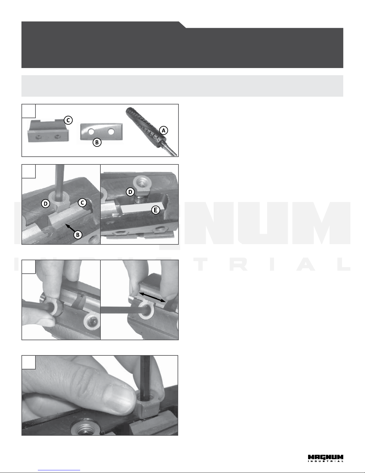
• Make sure carbide inserts are correctly and securely
installed in the cutterhead.
• Inspect stock and remove all foreign objects before
planing. Make sure that stock is clean and free of dirt,
nails, staples, rocks or any other foreign objects that could
damage the carbide inserts. Only process natural solid
wood boards. Never plane MDF, particle board, plywood,
laminates or any synthetic materials.
• Do not force material. e planer performs best when
working at the manufacturer's intended rate.
• To minimize the risk of injury from kickback, which
occurs when the workpiece is ejected by the force of the
cutterhead, use proper feeding technique and stand to one
side, out of the path of a potential kickback.
• Avoid working from awkward or o balance positions. Do
not overreach and keep both feet on oor.
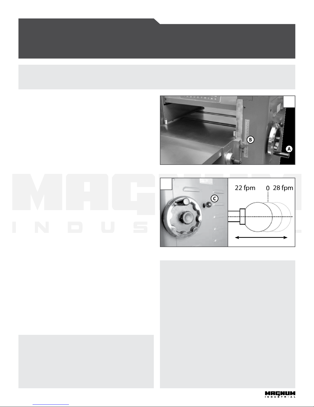
• Select appropriate feed speed for the stock being planed:
Use high speed for so wood and slow for hardwood.
• Place stock rmly against the table and use in-feed and
out-feed support if stock is too long.
• Keep guards in place and in working order. If a guard must
be removed for maintenance or cleaning, properly re-
attach it before using the planer again.
• Never leave the planer unattended while it is running or
with the power on.
• Never stand on machinery. Serious injury could result
if the planer is tipped over or if the belt or disc is
unintentionally contacted.
• Always disconnect the machine from the power source
before changing inserts; performing maintenance, cleaning
or servicing; or leaving the machine unattended.
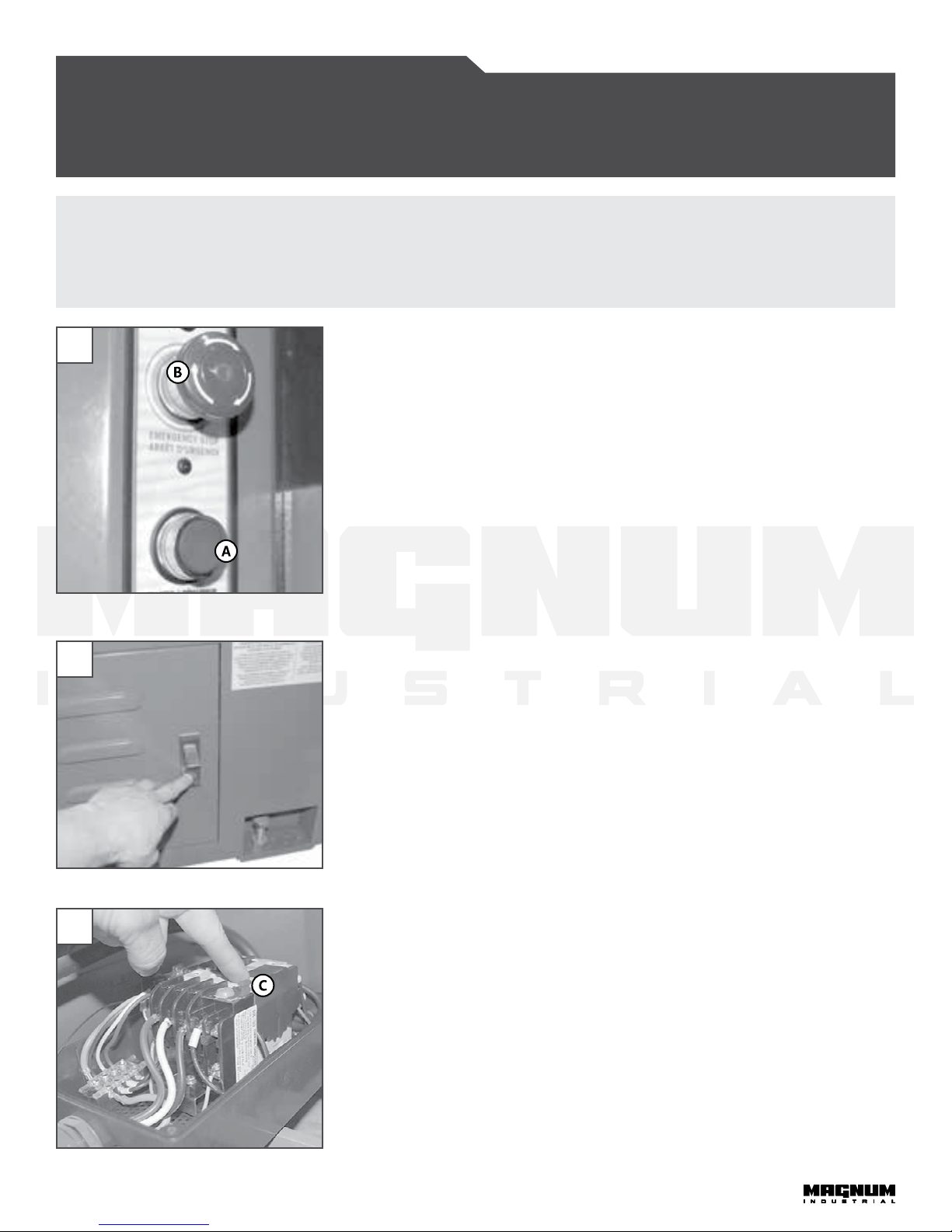
• Ensure the switch is in the OFF position before plugging in
the power cord.
• Make sure the machine is properly grounded. If equipped
with a three-prong plug, use it with a three-pole
receptacle. Never remove the third prong.
• Do not use this planer for other than its intended use.
If used for other purposes, KMS Tools and Equipment
disclaims any real or implied warranty and holds itself
harmless for any injury that may result from that use.
To help ensure safe operation, please take a moment to learn the how to operate the machine
and understand its applications and limitations, as well as potential hazards. KMS Tools and
Equipment disclaims any real or implied warranty and holds itself harmless for any injury that may
result from the improper use of its equipment.
RULES for SAFE OPERATION
MAGNUM INDUSTRIAL 20" HEAVYDUTY PLANER
MI-31550 / MI-31552 / MI-31553

2
TOOL OVERVIEW
MAGNUM INDUSTRIAL 20" HEAVYDUTY PLANER
MI-31550 / MI-31552 / MI-31553
FIGURE 1: TOOL OVERVIEW
MAIN COMPONENTS
(A)FRAME
(B)ON/OFF SWITCH
(C)TABLE EXTENSION
(D)DUST CHUTE
(E)RADUATED SCALE
(F)FEED SPEED ADJUSTMENT
()CUTTIN DEPTH ADJUSTMENT HANDWHEEL
(H)TABLE ROLLER ADJUSTMENT LEVER
1
ELECTRICAL REQUIREMENTS
Before connecting the machine to the power source, verify that the voltage of your power supply corresponds with the voltage
specied on the motor nameplate. A power source with greater voltage than needed can result in serious injury to the user as
well as damage to the machine. If in doubt, contact a qualied electrician before connecting to the power source. is tool is for
indoor use only. Do not expose to rain or use in wet or damp locations.
POWER CORD AND PLU
Because each installation situation is unique, this machine is supplied without a power cord or plug. An appropriate power
cord and plug must be installed by a qualied electrician. e machine must be connected to an electrical source using a power
cord that has a grounding wire, which must also be properly connected to the grounding prong on the plug. e outlet must be
properly installed and grounded and all electrical connections must be made in accordance with all local codes and regulations. A
manual circuit breaker is also recommended.
CIRCUIT CAPACITY
Make sure that the wires in your circuit are capable of handling the amperage draw from your machine, as well as any other
machines that could be operating on the same circuit. If you are unsure, consult a qualied electrician. If the circuit breaker trips
or the fuse blows regularly, your machine may be operating on a circuit that is close to its amperage draw capacity.
BASIC FUNCTIONS
e Magnum Industrial 20" heavy-duty planer is designed for thickness planing of solid wood only. e unit is not designed to
surface or prepare particle board, plywood, laminates, MDF, wood panelling or any other wood-based or non-wood based materials.
is planer has the capacity to plane boards up to 20” wide with a maximum thickness of 8” and a minimum thickness of 3/16”.

3
LIST OF CONTENTS
For your convenience this sander is shipped from the factory
partially assembled and requires only minimal assembly.
• (A)DUST CHUTE
• (B)CUTTIN DEPTH ADJUSTMENT HANDWHEEL
• (C)LIFTIN HOOK (X2)
• (D)FOOT PAD (X4)
• (E)LOCK KNOB (DEPTH OF CUT HANDWHEEL)
• (F)FLAT WASHER (DEPTH OF CUT HANDWHEEL)
• ()DUST CHUTE FLANE BOLT (X6)
• (H)SCREWDRIVER
• (I)METRIC ALLEN KEYS (3, 4, 6 MM)
• (J)METRIC WRENCHES (10, 14, 19, 24 MM)
• (K)HANDLE (TABLE ROLLER ADJ. LEVER)
• (L)THREADED ROD (TABLE ROLLER ADJ. LEVER)
For your convenience this machine is shipped from the factory partially assembled and requires only minimal assembly
and set up before being put into service.
• Before you assemble your band saw, review the parts breakdown and keep it ready for reference.
• Start by removing the parts from the packaging.
• Carefully check the packaging for small pieces before you continue.
• Lay out the parts on a large, clear and unobstructed area and ensure that all parts are accounted for.
• If you have any questions or require further information, please contact the KMS Tools Service Department at
FIGURE 2: CONTENTS
2
ASSEMBLY INSTRUCTIONS
MAGNUM INDUSTRIAL 20" HEAVYDUTY PLANER
MI-31550 / MI-31552 / MI-31553

4
INSTALLIN THE CUTTIN DEPTH
ADJUSTMENT HANDWHEEL
1. Position the handwheel on the arbor. See Figure 3.
2. Slide the FLAT WASHER (A)onto the arbor and secure it
in place with the LOCK KNOB (B).
INSTALLIN THE LIFT HOOKS
1. If needed, install the li hooks on top of the machine. See
Figure 4.
INSTALLIN TABLE ROLLER ADJUSTMENT
LEVER
1. Tighten the lever handle onto the sha. en tighten the
LEVER ASSEMBLY (C)into the BRACKET (D). See Figure 5.
INSTALLIN THE DUST CHUTE
1. Place the dust chute against the opening in the back of the
machine.
2. Align the MOUNTIN HOLES (E)in the dust chute with
the corresponding holes in the machine. Secure the chute
with the six FLANE BOLTS (F).Use a 10 mm wrench. See
Figure 6.
CONNECTIN TO A DUST COLLECTOR
e dust chute connects to a 5" hose. Make sure to use
appropriate sized hose and ttings (not included). Check that
all connections are sealed tightly to help minimize airborne dust.
WARNIN!
Before assembling the planer, make sure the
power cord is unplugged and the switch is in
the OFF position. Do not plug in or turn on
the machine until you have fully assembled
the machine.
ASSEMBLY INSTRUCTIONS
MAGNUM INDUSTRIAL 20" HEAVYDUTY PLANER
MI-31550 / MI-31552 / MI-31553
3
FIGURE 4: INSTALLING LIFT HOOKS
FIGURE 3: INSTALLING CUTTING DEPTH ADJUSTMENT HANDWHEEL
4
5
FIGURE 5: INSTALLING TABLE ROLLER ADJUSTMENT LEVER
FIGURE 6: INSTALLING DUST CHUTE
6

5
BASIC ADJUSTMENTS
MAGNUM INDUSTRIAL 20" HEAVYDUTY PLANER
MI-31550 / MI-31552 / MI-31553
WARNIN!
To reduce the risk of shock or fire do not operate the unit with a damaged power cord or plug.
Replace damaged cord or plug immediately. To avoid unexpected or unintentional start-up, make
sure that the power switch is in the OFF position before connecting to a power source.
7
FIGURE 7: MAGNETIC SAFETY SWITCH
8
FIGURE 8: MOTOR DOOR
FIGURE 9: RESETTING OVERLOAD SWITCH
9
CONNECTIN TO A POWER SOURCE
Once you have assembled the planer, plug the power cord into an appropriate
outlet. Refer to the Electrical Requirements section and follow all requirements and
grounding instructions.
MANETIC SAFETY SWITCH
is machine is equipped with a magnetic safety switch designed to protect the user
from unintentional startup. e switch assembly features a green START BUTTON
(A)and a red spring-loaded STOP BUTTON (B). Once the STOP BUTTON has been
pressed, restart the planer by turning the inner part of the button to the right. is
releases the stop button. See Figure 7.
OVERLOAD PROTECTION
e magnetic safety switch is equipped with an overload protection feature. In the
event of a spike in line voltage or amperage draw, the internal overload protector will
automatically trip and cut o power to the motor.
Electrical overloads can be caused by the following:
• Overworking the motor by forcing thick, dense material through the planer. is
causes an increase in power consumption and a spike in amperage draw.
• Using an electrical extension cord that is too long or not the correct gauge,
which can also cause an increase in amperage draw. If you are unsure about
choosing an appropriate power cord, contact a qualied electrician.
• Operating the machine on a circuit that is close to its amperage draw capacity.
Make sure the circuit is capable of handling the amperage draw from this
machine as well as any other electrical devices operating on the same circuit. If
you are unsure, consult a qualied electrician.
To reset the overload protection switch aer it has been tripped, follow these steps:
1. Unplug the machine.
2. Open the motor door in the back of the machine and remove electrical box cover.
See Figure 8.
3. Press the BUTTON (C)to reset the overload protection. See Figure 9.
4. Before starting the machine, secure the cover box and close the motor door.

6
WARNIN!
Before making adjustments, make sure the power cord is unplugged and the switch is in the OFF
position. Do not plug in or turn on the machine until you have fully assembled the machine.
ADJUSTIN TABLE ROLLER HEIHT
e planer features two adjustable TABLE ROLLERS (A)
that help reduce friction when feeding stock. You can set
the height of the rollers to suit personal preference as well
as the type of stock. See Figure 10.
As a general rule when planing rough stock, set the rollers
higher. When planing smooth stock, set the rollers lower.
To adjust the height of the table rollers follow these steps:
1. Loosen the LOCK LEVER (B)and turn the
ADJUSTMENT LEVER (C)up or down as needed.
2. Tighten the LOCK LEVER (B)to secure the rollers at the
desired height.
IMMOBILIZIN THE PLANER
During operation, vibration can cause the planer to move,
particularly when installed on an uneven surface.
Use the ANCHOR BOLTS (D)and pads to immobilize the
planer. Either lower the bolts against the pads on the oor
to act as points of contact with the oor, or for permanent
installation, drill into the oor and bolt the machine in
place. See Figure 11 for anchor bolt location.
BASIC ADJUSTMENTS
MAGNUM INDUSTRIAL 20" HEAVYDUTY PLANER
MI-31550 / MI-31552 / MI-31553
FIGURE 10: ADJUSTING TABLE ROLLERS
10
11
FIGURE 11: ANCHOR BOLTS

7
WARNIN!
Always plane in the direction of the grain. Planing against the grain or planing end grain is dangerous.
FIGURE 12: PLANER CAPACITY
12
OPERATIN INSTRUCTIONS
MAGNUM INDUSTRIAL 20" HEAVYDUTY PLANER
MI-31550 / MI-31552 / MI-31553
BASIC PRINCIPLES OF PLANIN
is planer is designed to remove material from the top face of a board in order to bring the board (or a series of boards)
down to a specic desired shape or prole and thickness. To obtain uniform results across the length of a board, the stock
being planed must have one face that has already been machined perfectly at (usually on a jointer) and the stock should
be fed with this at face against the table.
SELECTIN BOARDS
is planer is intended for use with solid woods or MDF only, and should not be used to plane or mould any other materials.
e workpiece should always be fed through the machine in the general direction of the grain in the wood. Before being fed
through the planer all lumber should be inspected for debris and foreign objects such as staples or nails.
Foreign objects embedded in your workpiece can be ejected from the machine at high speed, causing serious injury or
damaging cutter knives. Remove all foreign objects from the wood before planing it. Select lumber carefully and avoid
workpieces with loose or protruding knots. Also avoid workpieces that are twisted, severely deformed or warped.
Planing warped, twisted, damaged or fragile stock increases the risk of jamming or damaging the machine or cutters, as
well as increasing the risk of injury to the operator or bystanders from kickback. Kickback occurs when the workpiece is
forcefully or violently ejected from the machine.
WARNIN!
Respect the rated capacity of this machine. Ignoring these ratings and feeding non-compatible
stock into this planer can lead to serious injury to the user and/or bystanders and cause damage
to the workpiece and/or the machine. See Figure 12.
MAXIMUM THICKNESS: 8"
MINIMUM THICKNESS : 3/16"
MINIMUM LENGTH: 8 1/4"
MAXIMUM WIDTH: 8 1/4"

8
OPERATIN INSTRUCTIONS
MAGNUM INDUSTRIAL 20" HEAVYDUTY PLANER
MI-31550 / MI-31552 / MI-31553
WARNIN!
Before making any adjustments, ensure the power switch is OFF and the power cord is unplugged
ADJUSTIN CUTTIN DEPTH
You can adjust the cutting depth by turning the HANDWHEEL
(A). e maximum cutting depth on full width planing is 1/8".
For both hard and so wood, the planer is more eective when
removing less material per pass and taking multiple passes.
To adjust the cutting depth, follow these steps:
1. Turn o the machine.
2. Position the board under the infeed roller and adjust the
position of the table with the handwheel so that the infeed
roller touches the board.
3. Remove the board and adjust the cutting depth using the
SCALE (B)by turning the handwheel clockwise.
ADJUSTIN FEED SPEED
e feed motor speed operates at 22 or 28 feet per minute.
You can adjust the feed speed with the FEED SPEED
ADJUSTMENT KNOB (C), which located on the right side
of the planer. Choose the appropriate feed speed for the
stock: use high speed for so wood and slow for hardwood.
Experiment with feed speeds to nd the right speed for each
workpiece.
To increase the feed speed, see Figure 14 and follow these
steps:
1. To increase the feed rate to 28 fpm, pull the knob out.
2. To decrease the feed rate to 22 fpm, push the knob C in
3. To set the gearbox to neutral, move the knob C to the
middle position.
13
FIGURE 13: ADJUSTING CUTTING DEPTH
FIGURE 14: ADJUSTING FEED SPEED
14
PLANIN CHECKLIST
• Inspect the board and ensure it is suitable for planing.
• Wear appropriate workshop attire. Roll up long
sleeves, secure long hair and remove any jewellery,
watches, rings, bracelets or anything that could get
caught in moving parts.
• Wear eye, hearing and respiratory protection.
• Check that all components, including fasteners and
moving parts, are securely installed before starting
the planer.
• When planing multiple boards, collect them on a
nearby table within reach. To limit the potential for
injury in the event of a kickback, avoid stepping in
front of the planer to pick up the next workpiece.
WARNIN!
To avoid damaging to the gearbox, change
speeds only while the machine is running.

9
MAINTENANCE
MAGNUM INDUSTRIAL 20" HEAVYDUTY PLANER
MI-31550 / MI-31552 / MI-31553
REPLACIN CUTTERHEAD INSERTS
e HELICAL CUTTERHEAD (A)has 58 reversible CARBIDE
INSERTS (B), installed at the factory. Over time and with
normal use, these inserts need to be reversed and/or replaced.
To inspect the inserts for wear, manually turn the cutterhead.
To maintain even wear, always reverse or replace all 58 inserts
together.
To service the cutterhead, follow these steps:
1. Using an Allen key, loosen but do not remove the NUT
AND SCREW (D). Remove the INSERT HOLDER (C)and
INSERT (B). See Figure 16.
2. Clean the HOUSIN (E), INSERT HOLDER (C)and
INSERT (B)with lacquer thinner and a small brush. See
Figure 16.
3. Reverse or replace the INSERT and reinstall with the
INSERT HOLDER into the slot, then install the NUT AND
SCREW but do not tighten them yet.
4. Center the INSERT HOLDER (C)with the at edge of the
NUT and fully tighten the NUT AND SCREW. See Figure
17.
5. Follow steps 1 to 4 with the remaining inserts.
e NUTS AND SCREWS (D)that secure the INSERT
HOLDERS and INSERTS in the cutterhead do not have to be
removed when reversing or replacing the INSERTS.
If the NUTS AND SCREWS are removed, follow these steps to
ensure the chip breakers are secured at the same height:
1. Place the screw in the threaded hole and the nut on the
screw. Don't tighten yet.
2. While holding the nut, tighten the screw. is will tighten
both the screw and nut simultaneously
3. Do not thread the nut onto the screw before tightening
the screw into the threaded hole in the cutter head.
WARNIN!
Before making any adjustments, ensure the power switch is OFF and the power cord is unplugged
FIGURES 15 and 16: REPLACING CARBIDE INSERTS
FIGURE 17: REPLACING CARBIDE INSERTS
16
17
FIGURE 18: REPLACING CARBIDE INSERTS
18
15

10
MAINTENANCE
MAGNUM INDUSTRIAL 20" HEAVYDUTY PLANER
MI-31550 / MI-31552 / MI-31553
19
WARNIN!
Before performing any maintenance, ensure the power switch is OFF and the power cord is unplugged
REPLACIN EARBOX OIL
You should change the gearbox oil aer every 2,500 hours of
operation. Use 80W-90 gear oil. To change the gearbox oil,
follow these steps:
1. e gearbox is located behind the panel on the right
side of the planer. To remove the panel, rst remove the
handwheel. Next unthread and remove the feed speed
adjustment knob. en remove the panel.
2. Place a container under the DRAIN PLU (A)and
remove it using a 14 mm wrench. Once the gearbox
is drained, reinstall the DRAIN PLU (A), and then
remove the FILL PLU (B)using a 14 mm open wrench.
See Figure 19.
3. Fill the gearbox with a 80W-90 gear oil until it reaches
the hole. Reinstall the FILL PLU (B), and replace the
panel, handwheel and feed speed adjustment knob.
FIGURE 19: CHANGING THE GEAR OIL
PERIODIC MAINTENANCE
• Inspect the ON/OFF switches before each use. Do not operate the planer with a damaged switch. If you notice any damage to
the ON/OFF switch, replace it immediately.
• Keep the machine and table clean and free of sawdust, wood chips, pitch or glue. Regularly, vacuum or brush o loose debris
and wipe down the machine and the table.
• Occasionally apply a light coating of paste wax to help protect the table surface and reduce workpiece friction. Ask your local
branch for suggestions on aermarket surface cleaners and dry lubricants based on what is available in your area.
• Avoid using silicon-based products that could react with wood-nishing products such as varnishes and lacquers or oil-,
solvent- or water-based stains.
• Periodically inspect the power cord and plug. To minimize the risk of electrical shock or re, never operate the planer if you
notice its power cord or plug is damaged. Replace a damaged power cord or plug at the rst visible signs of damage.
• e drive gears, chain and elevation screws should be cleaned of wood chips, dust, debris and old grease. Aer cleaning, re-
lubricate according to the lubrication instructions on page 11. Don't over lubricate.
• Regularly inspect planed workpieces for signs of damaged or worn inserts. Replace damaged or worn inserts immediately.

11
LUBRICATION
MAGNUM INDUSTRIAL 20" HEAVYDUTY PLANER
MI-31550 / MI-31552 / MI-31553
FIGURE 20: LUBRICATING ELEVATION SCREWS
20
FIGURE 22: LUBRICATING CHAINS
22
FIGURE 24: LUBRICATING CHAINS
24
FIGURE 21: LUBRICATING SLIDING SURFACES
21
FIGURE 23: LUBRICATING CHAINS
23
FIGURE 25: LUBRICATING ROLLER SPRINGS
25
LUBRICATION
• Lubricate the ELEVATION SCREWS (A)SLIDIN SURFACES (B)and CHAINS (C)every month. Use all-purpose grease
for the CHAINS and ELEVATION SCREWS. Use all-purpose oil for the SLIDIN SURFACES. See Figures 20 to 24.
• Lubricate the spring rollers via the four SET SCREWS (D)aer every 30 hours of operation.
Use all-purpose oil. See Figure 25.
• e cutterhead bearings are lubricated and sealed at the factory and require no further maintenance.

12
MAINTENANCE
MAGNUM INDUSTRIAL 20" HEAVYDUTY PLANER
MI-31550 / MI-31552 / MI-31553
WARNIN!
Before performing any maintenance, ensure the power switch is OFF and the power cord is unplugged
27
CLEANIN ANTI-KICKBACK FINERS
is planer is equipped with ANTIKICKBACK FINERS (A)
that help prevent the workpiece from being violently ejected
from the machine. Check them periodically and ensure they
are clean and clear so they can move freely and operate
correctly. See Figure 26.
26
FIGURE 26: ANTI-KICKBACK FINGERS
ALININ PULLEYS
e drive belts and pulleys are located on the le side of the planer. To access them,
remove the upper and lower panels on the le side of the planer using a 4 mm Allen key.
Using a straight edge, check that the pulleys are properly aligned. See Figure 27. If
needed, align the pulleys by following these steps:
1. Open the motor access door.
2. Loosen the two NUTS (B)and the four NUTS (C)using 24 mm and 14 mm wrenches.
See Figures 28 and 29.
3. Reposition the motor on its mounting plate to align the pulleys.
4. Retighten the four NUTS (C)and the belt tension NUTS (B). Check tension by
pushing the belt with your nger. e belt should not move more than 1/2".
5. Close the motor access door
FIGURE 27: CHECKING BELT ALIGNMENT
FIGURE 28: ALIGNING DRIVE PULLEYS
28
FIGURE 28: ALIGNING DRIVE PULLEYS
29

13
MAINTENANCE
MAGNUM INDUSTRIAL 20" HEAVYDUTY PLANER
MI-31550 / MI-31552 / MI-31553
WARNIN!
Before performing any maintenance, ensure the power switch is OFF and the power cord is unplugged
ADJUSTIN BELT TENSION
Inspect the belts aer every 100 hours of use. To adjust belt
tension, rst remove the upper and lower panels on the le
side of the planer (refer to the instructions on page 12). Check
the belt tension by pushing the belt with your nger. e belt
should not move more than 1/2". If the belt is too slack, adjust
the tension:
1. Open the motor access panel. Loosen the two JAM NUTS
(A)and then raise or lower the two NUTS (B)with a 19
mm wrench to increase or decrease belt tension. See
Figure 30.
2. Retighten the JAM NUTS (A)against the motor mounting
plate.
3. Close the motor access door.
FIGURE 30: ALIGNING DRIVE PULLEYS
FIGURES 31 and 32: BELT INSTALLATION
30
31 CHANIN BELTS
If the belts show signs of wear, such as cracks or frays, replace them as soon as
possible.
1. Remove the NUTS (B).
2. Position a piece of wood under the motor base. See Figure 31.
3. Step on the wood to pivot the motor up, and then remove the belts from the
upper pulley.
4. Install the new belts, starting with the lower pulley. Reinstall the NUTS (B).
5. Adjust the tension (refer to the instructions in the section above).
6. Reinstall the le panels and close the motor access door before starting the
machine.
32

14
MANUM INDUSTRIAL 5-YEAR LIMITED WARRANTY
ank you for purchasing Magnum Industrial. Your new Magnum Industrial tool has been designed and manufactured
to deliver high-quality performance and dependability over a long service life. Before leaving the factory, every Magnum
Industrial product is tested and checked for quality.
5YEAR LIMITED WARRANTY
Magnum Industrial woodworking and metalworking machinery is backed by a 5-year limited warranty. is warranty covers
replacement parts against manufacturer's defect.
• is warranty does not cover parts that have been modied or damaged through misuse, lack of maintenance, negligence,
accidents, natural disasters, inadequate dust collection or excessive production demands.
• is warranty does not cover consumable parts or parts that are subject to regular wear and tear during normal operation.
Examples of wear and tear parts include drive belts, bearings and switches.
• is warranty does not cover parts damaged during shipping or transportation.
To make a warranty claim, the original purchaser must contact a Magnum Industrial representative and provide documented
proof of purchase. Once the representative conrms that the damage has occurred due to manufacturer's defect, Magnum
Industrial will ship a replacement part or parts prepaid to the original purchaser. e original purchaser may choose to install the
replacement parts or transport the machinery to an authorized Magnum Industrial service centre for installation. Transportation
costs are not covered by the warranty.
As determined on a case-by-case basis, parts may need to be inspected by an authorized Magnum Industrial representative
before parts are eligible for warranty. In these cases, the original purchaser is responsible for transporting the parts to a
representative or an authorized Magnum Industrial service centre.
LABOUR AND TRANSPORTATION COSTS
e original purchaser may choose to transport the machinery to an authorized Magnum Industrial service centre for warranty
evaluation. Transportation costs and expenses related to moving machinery to and from carrier vehicles are not covered by the
warranty.
Once the machinery has been evaluated by the authorized Magnum Industrial service centre, any parts damaged due to
manufacturer's defect will be replaced and installed at no cost. Labour is covered by warranty only when completed by an
authorized Magnum Industrial service centre. e warranty does not cover third-party repairs.
ORIINAL PURCHASER OF THE PRODUCT
is warranty is non-transferable and applies to the original purchaser only. is warranty requires documented proof of
purchase.
MANUAL
is manual is a guide for assembling and adjusting this product. It is not a woodworking or metalworking training manual.
It is the end user's responsibility to understand how to safely set up, operate, and maintain woodworking and metalworking
machinery. Because product specications can change without notice, some details in this manual may not apply to the product
you purchased.
DISCLAIMER
KMS Tools and Equipment and Magnum Industrial holds itself harmless for any injury or property damage that may result from
the use of this product.

43-1 43-2
43-3
43-4
43-5
43-6
PARTS LIST FOR MI-31550 / MI-31552 / MI-31553
43.1
6
7
2
3
4
5
1

PARTS LIST FOR MI-31550 / MI-31552 / MI-31553

PARTS LIST FOR MI-31550 / MI-31552 / MI-31553

PARTS LIST FOR MI-31550 / MI-31552 / MI-31553

ITEM NO. DESCRIPTION SPECIFICATION QTY
MI-31550-1 DUST CHUTE 1
MI-31550-2 HEX SCREW W/WASHER M6*1.0P*12 13
MI-31550-3 RIGHT+E25 1
MI-31550-4 FLAT WASHER 6.7*19*2.0t 7
MI-31550-6 CHIP PLATE 1
MI-31550-7 SOC HD CAP SCREW M6*1.0P*12 4
MI-31550-8 REAR TOP COVER 1
MI-31550-9 ROUND HEAD HEX SCREW M6*1.0P*10 39
MI-31550-10 FRONT TOP COVER 1
MI-31550-11 PAD 2
MI-31550-12 SPRING PLATE 2
MI-31550-13 SHAFT 1
MI-31550-15 HEX NUT M6*1.0P(10B*5H) 6
MI-31550-16 CHIP BREAKER 1
MI-31550-17 RETAINING RING ETW-10 4
MI-31550-18 SHAFT 1
MI-31550-19 FIXING PLATE 4
MI-31550-20 SET SCREW M5*0.8P*5 13
MI-31550-21 FIXING SHAFT 2
MI-31550-22 SPRING 4
MI-31550-23 BUSHING 4
MI-31550-24 OUTFEED ROLLER 1
MI-31550-25 KEY 5*5*22 1
MI-31550-26 CHAIN SPROCKET 1
MI-31550-27 CHAIN #06B*85P 1
MI-31550-29 CHAIN #06B*58P 1
MI-31550-30 RETAINER PLATE 4
MI-31550-31 HEX. SCREW M6*1.0P*16 17
MI-31550-32 SET SCREW M6*1.0P*16 6
MI-31550-33 SOC HD CAP SCREW M8*1.25P*20 6
MI-31550-34 SPRING WASHER 8.2*15.4 19
MI-31550-35 FLAT WASHER 8.5*23*2.0t 16
MI-31550-36 SCREW 4
MI-31550-37 LEFT SUPPORT SHAFT 1
MI-31550-38 HEX. SCREW M8*1.25P*20 4
MI-31550-39 WASHER 1
MI-31550-40 CUTTERHEAD PULLEY 1
MI-31550-41 FLAT WASHER 6.2*22*3t 7
MI-31550-42 RETAINING RING RTW-72 1
MI-31502-43 CUTTERHEAD COMPLETE (MI-31502)1
MI-31502-43-1 KNIFE 4
MI-31502-43-2 KNIFE LOCKING BAR 4
MI-31502-43-3 HEX HEAD BOLT M8X1.25PX10 6
MI-31502-43-4 SPRING 9
MI-31502-43-5 HEX HEAD BOLT M5X0.8PX12L 12
MI-31502-43-6 CUTTERHEAD 1
MI-31550-43.1 HELICAL CUTTREAD(MI-31550 / MI-31552 / MI-31553) 1
MI-31550-43.1-1 CUTTER HEAD 1
MI-31550-43.1-2 INSERT SCREW 58
MI-31550-43.1-3 NUT 58
MI-31550-43.1-4 KNIFE-HOLDER / CHIPBREAKER 58
MI-31550-43.1-5 CARBIDE INSERT 30X12X1.5MM (T) 58
MI-31550-43.1-6 “T” HANDLE ALLEN WRENCH 5 MM 1
MI-31550-43.1-7 ALLEN KEY 5 MM 1
MI-31550-45 BALL BEARING 6207 1
MI-31550-46 KEY 8*8*40 1
MI-31550-47 SPRING 1
MI-31550-50 BALL BEARING 6006 1
MI-31550-51 GEAR 1
MI-31550-52 WASHER 39*69*2t 2
MI-31550-53 RETAINING RING STW-38 2
MI-31550-54 RUBBER PIN 120
MI-31550-55 INFEED ROLLER 20
MI-31550-56 INFEED ROLLER SHAFT 1
MI-31550-57 CHAIN SPROCKET 1
MI-31550-58 ANTI-KICK BACK SHAFT 2
PARTS LIST FOR MI-31550 / MI-31552 / MI-31553
HELICAL CUTTERHEAD
CUTTERHEAD
This manual suits for next models
2
Table of contents
Other Magnum Industrial Planer manuals