Magnum Industrial MI-31170 User manual

MODEL NO.:
OPERATING MANUAL
MI-31170

UNPACKING & INVENTORY
Check shipping carton and machine for damage before unpacking. Carefully remove packaging
materials, parts and machine from shipping carton. Always check for and remove protective shipping
materials around motors and moving parts. Lay out all parts on a clean work surface.
Remove any protective materials and coatings from all of the parts and the planer. The protective
coatings can be removed by spraying WD-40 on them and wiping it off with a soft cloth. This may
need to be redone several times before all of the protective coatings are removed completely.
After cleaning, apply a good quality paste wax to any unpainted surfaces including the infeed,
outfeed, and center tables. Make sure to buff out the wax before assembly.
Compare the items to inventory figures and verify that all items are accounted for. If at all possible,
retain shipping carton for warranty service if ever needed.
If any parts are missing, do not attempt to plug in the power cord and run the machine. The machine
should only be turned “ON” after all the parts have been obtained and installed correctly.
NOTE: Some parts may have been installed at the factory. Please check before calling.
For missing parts, contact xxx.
1. DUST PORT 1 pc
2. HEX WRENCH 4mm x 100 1 pc
3. TORX WRENCH 1 pc
4. RAISE / LOWER HANDLE 1 pc
5. HEX SCREW M5*P0.8*20 1 pc
6. DUST PORT KNOB 2 pcs
1 2
3
4
5
6

2
ASSEMBLY
WARNING! MAKE CERTAIN THAT THE MACHINE IS DISCONNECTED FROM THE
POWER SOURCE.
ATTACHING DEPTH ADJUSTMENT HANDLE
Attach the raise/lower adjustment handle to the shaft located on top of the planer and fasten in place
with 1 Hex Socket Head screw. Tighten screw using supplied hex wrench. SEE FIG 1.
FIG 1
ATTACHING DUST PORT
1. Facing the rear of the machine, locate the dust port on the cutterhead assembly by turning 2
dust port knobs. SEE FIG 2.
FIG 2

3
ASSEMBLY (cont.)
2. To minimize sawdust accumulation on your work piece, attach either a 2-1/2 in. or a 4 in.
vacuum hose to the dust port.
3. The dust port must be snapped shut completely or chips may fly out of the front of the planer.
4. The dust port can be opened to allow chips to flow out the back of the planer when a vacuum
system is not used. SEE FIG 3.
FIG 3
SECURING PLANER TO A TABLE OR WORKBENCH
During operation, if there is any tendency for the planer to tip over, slide or walk, the planer
MUST be secured to a supporting surface such as a workbench or table. Four holes are
provided (2 are shown at A below) to securely mount the planer. The surface you are mounting
the planer to should be perfectly flat. SEE FIG 4.
FIG 4
A

4
ADJUSTMENTS
WARNING! MAKE CERTAIN THAT THE MACHINE IS DISCONNECTED FROM THE POWER
SOURCE BEFORE ANY ADJUSTMENTS ARE MADE.
LEVELING EXTENSION TABLES
The extension tables must be level with the planer table. To check the extension tables and adjust if
necessary:
1. Lay a straight edge (A) on the planer table (C) with one end of the straight edge over the infeed
table (B). SEE FIG 5.
2. Check to make sure that the infeed table is level with the planer table.
3. If an adjustment is necessary, raise table, loosen lock nuts (D) and adjust Hex Head Screws (E)
on each side of the table until the infeed table is level with the planer table. This will adjust the
outer edge of the table.
4. Recheck for level and repeat adjustment if necessary.
5. Repeat this process for leveling the outfeed table.
FIG 5
E
D
C
A
B

5
ADJUSTMENTS (cont.)
RAISING AND LOWERING HEAD ASSEMBLY
The head assembly consists of the cutterhead, knives, feed rollers, cutterhead guard, and the motor.
Raising and lowering of the head assembly controls the depth of cut on the planer.
To adjust:
1. To raise the head assembly (A), turn the adjusting handle (B) clockwise. SEE FIG 6.
2. To lower the head assembly, turn the adjusting handle counterclockwise.
NOTE: One revolution of the handle will move the cutterhead up or down approximately 1/16”. You
can confirm this by referencing the scale (C) on the front right side of the planer.
FIG 6
NOTE: The Repeat Cut Thickness Indicator (D), located on the bottom right side of the planer,
provides a simple way to preset the finished thickness of a work piece. Rotate the indicator to the
desired finished thickness. Use this feature when thickness planing multiple work pieces to ensure a
uniform thickness of all work pieces. See page 20 for more information. Do not attempt to lower the
cutterhead assembly below the preset level as damage will occur.
A
B
C
D

6
ADJUSTMENTS (cont.)
ADJUSTING / REPLACING KNIVES FOR THE SPIRAL CUTTERHEAD
WARNING! MAKE CERTAIN THAT THE MACHINE IS DISCONNECTED FROM THE POWER
SOURCE BEFORE ANY ADJUSTMENTS ARE MADE.
WARNING! *** Be VERY CAREFUL when handling the knives or cutter tips as they are
EXTREMELY SHARP and can cause serious injury!!! ***
This 13" cutterhead is equipped with 26 indexable cutter inserts. Each cutter insert can be rotated to
reveal one of its two cutting edges. Therefore, if one cutting edge becomes dull or damaged, simply
rotate it 90° to reveal a fresh cutting edge.
In addition, each cutter insert has a reference dot on one corner. As the cutter insert is rotated, the
reference dot location can be used as an indicator of which edges are used and which are new.
When the reference dot revolves back around to its starting position, the cutter should be replaced.
WARNING! NEVER GRASP CUTTERHEAD
BY HAND AS THIS WILL
RESULT IN SERIOUS INJURY!
To rotate or change cutter tip inserts:
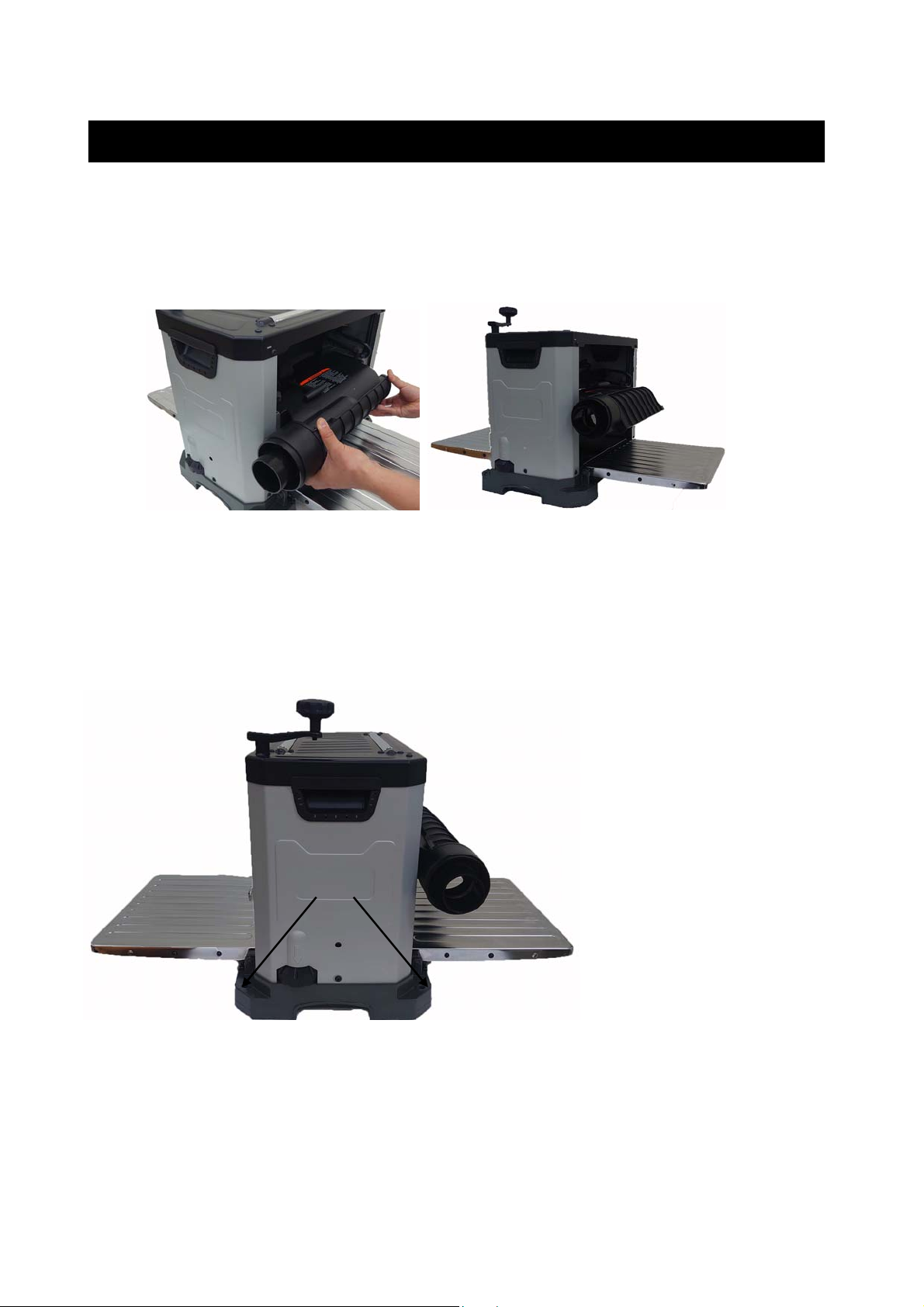
1. Face the rear of the machine. Remove the Dust Port. Refer back to the section labeled
ATTACHING DUST PORT in the ASSEMBLY section page 13 for information on removal.
2. Use the handle to lower the cutterhead assembly down to about 1” on the scale.
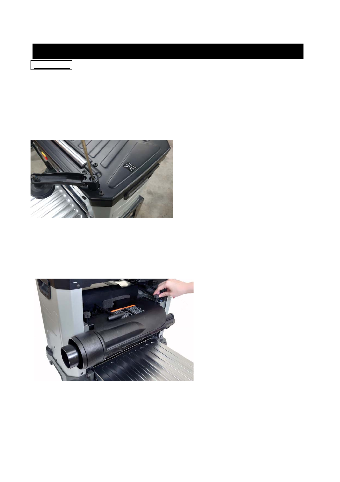
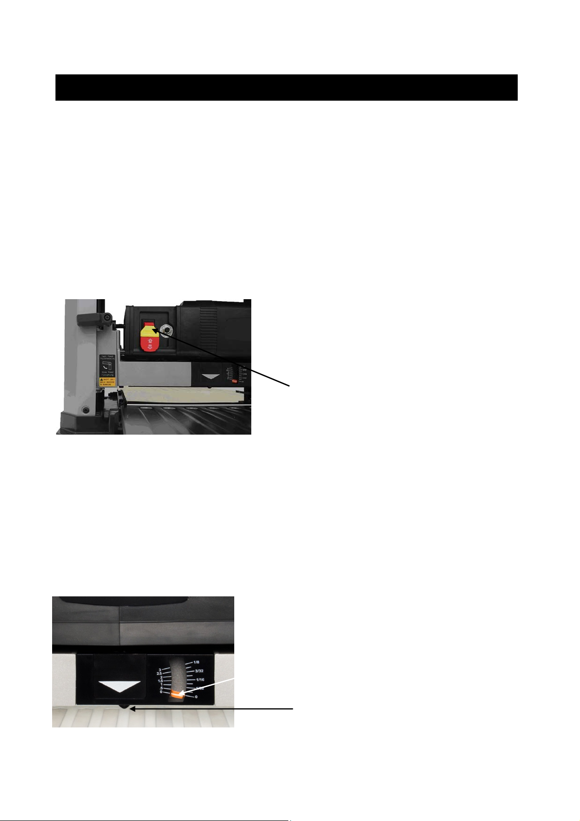
3. Insert the supplied Hex wrench through the hole located on the side of the machine beside
the Repeat Cut indicator. Rotate the cutterhead to a position where a cutter tip is visible. SEE
FIG. 7. next page. (You may have to raise or lower cutterhead to be able to insert the Hex
wrench into the cutterhead)
4. While holding the hex wrench to prevent cutterhead rotation, remove the cutter tip screw
using the provided Torx T-wrench allowing the tip to be removed.
5. Carefully clean all dust and dirt off the cutter tip and the cutterhead seat. Replace or rotate the
cutter insert so a fresh sharp edge is facing outward. If available, use pitch remover to be sure
all wood residue is off the cutterhead, cutter insert, and screws, before attempting to rotate or
replace them. Using a shot of compressed air is also helpful. Be sure to wear safety glasses
when using compressed air.
6. Lubricate the Torx screw threads with light machine oil and wipe the excess oil off the threads.
Install cutter tip insert and torque the Torx screw to 48-50 lb-ft.

7
ADJUSTMENTS (cont.)
FIG 7
Note: Proper cleaning of tips and cutterhead is critical to achieving a smooth finish. Dirt or
dust trapped between the cutter insert and cutterhead will slightly raise the cutter insert, and
make noticeable marks on your work piece the next time you plane.
THICKNESS SCALE ADJUSTMENT
The thickness scale, located on the right of the planer, shows the thickness of the finished work
piece. To make sure the scale is set properly, run a piece of wood through the planer and measure
the thickness of the wood. If the scale is out of alignment, loosen the two round head screws (A)
holding the scale indicator (B) and adjust the thickness indicator to the correct setting. Make sure to
re-tighten the two screws once the adjustment is complete. SEE FIG 8.
FIG 8

8
OPERATIONS
NOTE: This operations section was designed to give instructions on the basic operations of this
planer. However, it is in no way comprehensive of every planer operation. It is strongly recommended
that you read books, trade magazines, or get formal training to maximize the potential of your planer
while minimizing the risks.
NOTE: This planer is designed to process wood ONLY.
POWER SWITCH
The planer is turned on by flipping the switch into the up position and it is turned off by flipping the
switch in the down position. This planer is also equipped with a special lockout toggle switch that
prevents unauthorized use. To prevent unauthorized use of the planer, simply pull out the yellow key
(A) located on the face of the switch. SEE FIG 9.
FIG 9
DEPTH-OF-CUT INDICATOR
The Depth-Of-Cut Indicator, located on the front of the machine, is a convenient way to quickly
determine how much material is being planed off in one pass.
1. With the machine OFF, insert your work piece just under the cut scale (A). SEE FIG 10.
2. Crank the raising / lowering handle until the button (B) comes in contact with the work piece.
As you rotate the raise / lower handle, the needle on the depth of cut scale will move showing
how much material will be removed in that pass.
FIG 10
A
A
B

9
OPERATIONS (cont.)
REPEAT CUT PRESET
The REPEAT CUT preset, located on the right side of the planer, provides a simple way to preset the
finished thickness of a work piece. The indicator can be set to various thicknesses. Rotate the
indicator to the desired finished thickness. Use this feature when thickness planing multiple work
pieces to ensure a uniform thickness of all work pieces. SEE FIG 11.
FIG 11
NOTE: When lowering the head assembly, ensure the REPEAT CUT preset is in the lowest desired
thickness position. Failure to do so may result in excess downward pressure by the cutterhead
assembly onto the mechanism and cause damage to the adjustment rod and upper frame.
FEED RATE
CAUTION! ONLY SWITCH FEED RATE SELECTOR WHILE PLANER IS RUNNING..
Switch feed rate selector (A) to slow feed (16FPM) for finishing or fast feed (26FPM) for thicknessing.
SEE FIG 11-1.
FIG 11-1
A

10
OPERATIONS (cont.)
GETTING PREPARED
It is always a good idea to use a piece of scrap wood for your first planing attempt. Also, before each
use of the planer, make it a habit of checking for loose fasteners, fittings or hardware. Turn the planer
ON and allow it to reach full speed. Pay close attention to any excessively loud noises that may be
coming from the planer or any excessive vibration. If either occurs, shut down the planer immediately
checking again for loose hardware. Go through the ASSEMBLY and ADJUSTMENTS sections again
if necessary.
BASIC OPERATION
WARNING! To avoid serious personal injury, NEVER stand directly in line with the front or rear of
the planer. If an object is thrown from the planer, it will travel in this direction.
1. Stand to either the left or right side of the planer.
2. Flip the switch to the ON position.
3. Lift the work piece onto the infeed table by grabbing the edges of the board at the middle of
the length. NOTE: For longer pieces, be sure to use additional supports or stands.
4. Push slightly on the board to start feed and allow the feed rollers to pull the board through
the planer. Once the feed rollers start to pull the work piece through, let go of the board and
allow the rollers to do their job. DO NOT push or pull on the work piece once the rollers have
engaged.
5. Move to one side of the rear of the planer and receive the planed work piece by grabbing the
edges of the wood like you did when feeding the work piece in.
6. It normally takes several passes of varying depths to achieve a smooth finish, so repeat this
process as many times as necessary. Remember the less you take off in a pass, the
smoother the finish will be, but you may still need to finish the surface by sanding.
THICKNESS PLANING
Thickness planing sizes the work piece to a desired thickness, while at the same time creating a
smooth and level surface. The thickness of each cut will depend on the type of wood, width of the
work piece, and condition of the lumber (i.e. dryness, grain composition, straightness, etc). Always
make thin test cuts on a scrap piece of wood prior to performing final cuts.
GENERAL TIPS AND GUIDELINES
1. Thickness planing always works best when at least one side of the work piece has a flat
surface. If both sides of the work piece are rough, feed one face of the board through the planer
until the entire surface is flat.
2. ALWAYS plane both sides of the work piece to reach the desired thickness.
3. DO NOT plane work pieces less than 1/8” thick, less than 3/4-in wide, or shorter than 7-in.
4. It is not recommended to continuously use the planer at its maximum depth of cut (1/16”) and at
its full width (13”) as this will shorten the life of the motor.
5. Light cuts create a smoother finish than heavier cuts.
6. If a smooth cut is not obtained, see TROUBLESHOOTING GUIDE on page 24.

11
OPERATIONS (cont.)
AVOIDING SNIPE
Snipe, gouging or depression of the board at the ends, can occur when the board is not properly
supported. For work pieces longer than 4 ft, greater care must be taken to reduce the problem
because the additional length of the work piece translates into more unsupported weight pulling
down on the end of the board. This unsupported weight will work against keeping the stock flat.
Make sure to use supports or stands whenever long pieces are being planed to avoid this problem.
Since snipe occurs at the end of the boards, it is good practice to start with a work piece that is
slightly longer than what you need so that you can simply cut off the ends if necessary.
Also see TROUBLESHOOTING for further information.
MAINTENANCE
WARNING! MAKE CERTAIN THAT THE MACHINE IS DISCONNECTED FROM THE POWER
SOURCE BEFORE PERFORMING ANY MAINTENANCE PROCEDURES
Your planer should provide you with a long time of service provided you take the time to perform the
following maintenance operations.
CLEANING
Sawdust buildup and other debris can cause the tool to plane incorrectly. Periodic cleaning and
waxing is needed for accurate, precision planing. Any moving parts should be cleaned regularly with
a penetrating oil and lubricated with a light coating of medium weight machine oil
CAUTION! With the machine unplugged, blow off motor with low pressure air to remove dust or
dirt. Air pressure above 50 P.S.I. should not be used as high-pressured air may damage insulation.
The operator should always wear a respirator and eye protection when using compressed air. Do not
allow chips and dust to accumulate under the machine. Keep area clean and in safe order.
Having clean feed rollers is essential for optimal results. Check feed rollers after each use for buildup
of pitch, gum, or resin, and be sure to clean off with a non-flammable tar and pitch remover that is not
harmful to rubberized surfaces.
Periodically clean, wax, and buff the tables. This will aid in the prevention of improper feeding of the
work piece.
HARDWARE TIGHTNESS
Periodically check all clamps, nuts, bolts, and screws, for tightness and condition. Stop the machine
and recheck the cutterhead screw and knives, or tips, for tightness after about 50 hours of operation.
Recheck periodically.

12
MAINTENANCE (cont.)
BRUSH REPLACEMENT
Brush life will vary depending on the load placed on the motor. The brushes should be inspected
every 10-15 hours of use. To inspect or replace:
1. Remove the brush holders, one of which is shown at (A). The other is located in the same
position on the rear of the motor assembly. The Brush Holder can be removed using a flat
blade screwdriver. SEE FIG 12
FIG 12 FIG 13
2. Once the brush has been removed, inspect the carbon (B), the spring (C), and the wire (D).
SEE FIG 13.
3. If the carbon of either brush is worn down to 3/16” or less, both brushes should be replaced.
Also if the spring or wire are burned or damaged in any way, both brushes should be replaced.
A
B
C
D

13
TROUBLESHOOTING GUIDE
Motor and Machine Operation
PROBLEM LIIKELY CAUSE SOLUTION
Snipe
(depressions at
end of work piece)
Dull Blades
Infeed or outfeed tables out of
adjustment.
Residue on rollers.
Replace or rotate tips. Readjust
tables. Feed scrap of same thickness
before and after work piece.
Clean rollers.
Torn grain. Too deep or shallow blade
setting.
Work piece being fed against
grain.
Dull cutter blades
Reduce or increase the depth of cut.
Feed other end of board first.
Replace or turn blades.
Try skewing board when feeding.
VERY slightly dampen work piece.
Fuzzy/rough grain. High wood moisture content.
Dull blades
Too deep a blade setting.
Dry wood before planing.
Replace or turn blades
Reduce depth of cut
Board thickness
does not match
depth scale indicator.
Depth scale incorrectly set. Adjust depth scale.
Will not start. Not plugged in.
Blown circuit.
Lockout key removed.
Check the power source.
Replace fuse, reset breaker, or call
electrician.
Replace lockout key.
Interrupted operation Unit overloaded.
Circuit overloaded.
Reduce load.
Operate on circuit separate from
other appliances or motors or
connect to circuit with adequate amp
rating.
Planer not feeding
properly
Too much material being
removed.
Knives or tips dull.
Build up on tables.
Build up on rollers.
Reduce cut depth.
Replace knives or tips.
Clean tables and apply paste wax.
Clean rollers with a cleaner safe for
rubber surfaces.

14
PARTS
97

ITEM NO. DESCRIPTION SIZE Q'ty
MI-31170-01 TOP COVER 1
MI-31170-02 HEX SOC HD CAP SCR M6xP1.0x8L 14
MI-31170-03 SHAFT BUSHING 3
MI-31170-04 ELEVATION NUT 8
MI-31170-05 RETAINER BEARING for top cover2 1
MI-31170-06 UPPER FRAME 1
MI-31170-07 LEFT SIDE PANEL 1
MI-31170-08 RIGHT SIDE PANEL 1
MI-31170-09 KNOB 2
MI-31170-10 HANDLE BAR 2
MI-31170-11 SCR HEX SOC BUT HD M6xP1.0x10L 13
MI-31170-12 SCR PAN CR TAP M3xP1.0x16L 2
MI-31170-13 IDLE WHEEL 3
MI-31170-14 IDLE WHEEL SHAFT 3
MI-31170-15 SPINDLE 3
MI-31170-16 HEIGHT ADJ SPINDLE 1
MI-31170-17 HEX SOC HD SCR M5xP0.8x20L 1
MI-31170-18 HANDLE ASSEMBLY #18A~18F 1
MI-31170-19 BASE 1
MI-31170-20 HEX WRENCH 1
MI-31170-21 TORX WRENCH 1
MI-31170-22 BELT GUARD 1
MI-31170-23 SPACER 1
MI-31170-24 NYLOCK SCR SOC SET CUP PT M5XP0.8X5L 1
MI-31170-25 POINTER 1
MI-31170-26 ELEVATING NUT 1
MI-31170-27 CUTTERHEAD PULLEY 1
MI-31170-28 BASE BEARING RETAINER 4
MI-31170-29 SPRING COIL 1
MI-31170-30 SPECIAL WASHER 4
MI-31170-31 SPRING 1
MI-31170-32 STEEL BALL 1
MI-31170-33 SPROCKET 4
MI-31170-34 SCR SEMS L/WASH 1
MI-31170-35 STEP BLOCK 1
MI-31170-36 STEP BLOCK BASE 1
MI-31170-38 SPECIAL WASHER 4
MI-31170-39S DUST HOOD ASSY. #9+#12+#39~42+#203 1
MI-31170-44 SPRING FLAT 4
MI-31170-45 SCR SEMS S/WASH M5XP0.8X10L 8
MI-31170-46 SCR SEMS W/WASH M4XP0.7X10L (M4X10X0.8T) 10
MI-31170-47 SCREW M5XP0.8X8L 3
MI-31170-48 DUST CHUTE PLATE 1
MI-31170-49 NYLOCK SCR SOC SET CUP PT M5XP0.8X8L 1
MI-31170-50 SCR PAN CR M5XP0.8X8L 1
PARTS LIST FOR MI-31170

ITEM NO. DESCRIPTION SIZE Q'ty
MI-31170-51 CORD CLAMP 2
MI-31170-52 SCR HEX SOC HD LOCK M4XP0.7X10L 2
MI-31170-53 WASHER 2
MI-31170-54 WASHER 1
MI-31170-55 SCREW HEX HD M8XP1.25X20L 1
MI-31170-56 GEAR (INTERMEDIATE) 1
MI-31170-57 RING RETAINING EXT 1
MI-31170-58 GEAR SPINDLE 1
MI-31170-59 RING RETAINING EXT 1
MI-31170-60 FEED RATE SELECTOR 1
MI-31170-61 KEY 1
MI-31170-62 SPLINED SPINDLE 1
MI-31170-63 BEARING RETAINER 1
MI-31170-64 WASHER 1
MI-31170-65 MOTOR PULLEY 1
MI-31170-66 V-BELT 1
MI-31170-67 NUT HEX 1
MI-31170-68 BALL BEARING 2
MI-31170-69 CUTTER INSERT 26
MI-31170-70 SPIRAL CUTTERHEAD 1
MI-31170-71 TORX SCREW M5XP0.8X15.6L 26
MI-31170-72 NUT HEX SPECIAL M8XP1.25X13 1
MI-31170-73 ROD STEP 1
MI-31170-74 NUT HEX M5XP0.8 1
MI-31170-75 SCRW HEX HD M5XP0.8X25L 1
MI-31170-76 SCREW M5XP0.8X6L 8
MI-31170-77 SCREW PAN CR M3XP0.5X20L 2
MI-31170-78 SPECIAL HEX SOC HD CAP SCR M5XP0.8X12L(4MM) 8
MI-31170-79 NUT M4 1
MI-31170-80 DEPTH OF CUT 1
MI-31170-81 CURSOR 1
MI-31170-82 BUSHING 1
MI-31170-83 PHILLIPS SCREW M4XP0.7X10L 1
MI-31170-84 COVER POINTER 1
MI-31170-85 SPRING COIL 8.5X19X0.8 1
MI-31170-86 ROD POINTER ELEVATING 1
MI-31170-87 SCR PN CR TYTT M5XP0.8X8L 2
MI-31170-88 LOCKWASHER EXT 2
MI-31170-89 FEED RATE LABEL 1
MI-31170-90 C-RING 4
MI-31170-91 SPROCKET 3
MI-31170-92 CHAIN WHEEL 2
MI-31170-93 SPRING 2
MI-31170-94 BLOCK BEARING 4
MI-31170-95 OUTFEED ROLLER 1
PARTS LIST FOR MI-31170

ITEM NO. DESCRIPTION SIZE Q'ty
MI-31170-96 SPRING 2
MI-31170-97 PLATE RETAINER 4
MI-31170-98 SCR HEX SOC CAP M5XP0.8X10L 8
MI-31170-99 INFEED ROLLER 1
MI-31170-101 GEAR 1
MI-31170-101A GEAR BOX 1
MI-31170-115 SPACER 15X20X8.5 1
MI-31170-116 SCR SEMS L/WASH M5XP0.8X12L 11
MI-31170-117 BASE GUIDE RAIL 2
MI-31170-118 WEAR PLATE 1
MI-31170-119 TABLE 2
MI-31170-128 SCALE 1
MI-31170-129 SPACER 4
MI-31170-130 GASKET FOAM 1
MI-31170-131 SCR HEX SOC HD LOCK 2
MI-31170-132 CONNECTING ROD 1
MI-31170-133 GEARBOX COVER 1
MI-31170-134 SCR PAN CR M5XP0.8X10L 3
MI-31170-136 BOLT ADJUSTING M10XP1.5 4
MI-31170-137 NUT HEX SPECIAL 4
MI-31170-140 SCREW HEX M6XP1.0X25L 4
MI-31170-141 NUT HEX 4
MI-31170-142 BALL BEARING 5
MI-31170-143 WA SHER 4
MI-31170-144 SCR HEX SOC CAP M4XP0.7X12L 4
MI-31170-146 CHAIN 1
MI-31170-147 SCR HEX SOC CAP M5XP0.8X25L 3
MI-31170-155 WASHER 4
MI-31170-164 WASHER 4
MI-31170-191 LOGO LABEL 1
MI-31170-195 SPEC LABEL 1
MI-31170-203 WARNING LABEL 1
MI-31170-250S MOTOR ASSY. 1
MI-31170-253 BRUSH HOLDER 2
MI-31170-254 BRUSH 2
MI-31170-255 BRUSH CAP 2
MI-31170-273 SWITCH 1
MI-31170-274 KEY 1
PARTS LIST FOR MI-31170
Table of contents
Other Magnum Industrial Planer manuals
Popular Planer manuals by other brands

Freud
Freud FE82 Spare parts list

General International
General International 30-010 MI Setup & operation manual

Scheppach
Scheppach 4902205901 Translation from the original instruction manual

Porter-Cable
Porter-Cable PC60THP instruction manual

Ryobi
Ryobi AP1300 Operator's manual

Woodstock
Woodstock PLANER PAL W1226 Instructions for use