General 30-360 Parts list manual

SETUP & OPERATION MANUAL
Version #1_Revision #2 - November 2015
© Copyright General International
20” SINGLE SURFACE PLANER
MODEL
#30-360
#30-360HC*
FEATURES
Positive gear design for quick and accurate
table adjustments.
5” dust collection hood.
Cast-iron table and head.
Four cutter knives result in easier cutting and
longer motor life, (helical cutter head model
available: #30-360HC).
Built-in table rollers reduce friction.
Large 8” handwheel quickly adjusts table
height.
Comes with magnetic safety switch.
Graduated scale in both inches and metric to
indicate workpiece thickness.
Anti-kickback fingers at the front of the infeed
roller to ensure maximum operator safety.
Vertical adjustment handle for table rollers.
Equipped with a sectioned infeed roller and a
rubber outfeed roller.
One front-mounted exterior table roller.
SPECIFICATIONS
• Table size
32” x 20” (813 x 508 mm)
• Maximum planing width
20” (508 mm)
• Min/Max thickness of stock
3/16” (5 mm) / 8” (204 mm)
• Minimum length of stock
8 1/4” (210 mm)
• Maximum cutting depth (full width)
1/8” (3 mm)
• Maximum cutting depth (width 8 1/2” or less)
1/4” (6 mm)
• Cutter head diameter
3 3/4” (97 mm)
• Cutter head speed
4500 rpm
• Feed speeds
(2) 22 & 28 fpm
• Cuts per inch (not applicable for HC model)
68.17 at 22 fpm & 53.5 at 28 fpm
• Number of knives / Inserts
4 - 30-360 / 58 - 30-460HC
• Base dimensions (l x w)
36” x 22” (914 x 559 mm)
• Motor
M1: 7 1/2 HP, 220 V, 1 Ph, 31 A
M2: 7 1/2 HP, 220 V, 3 Ph, 20 A
M3: 7 1/2 HP, 600 V, 3 Ph, 10 A
• Weight
1392 lbs (633 kg) - 30-360
1397 lbs (635 kg) - 30-360HC
*With helical cutter head

GENERAL® INTERNATIONAL
8360 Champ-d’Eau, Montreal (Quebec) Canada H1P 1Y3
Telephone (514) 326-1161 • Fax (514) 326-5555 • www.general.ca
THANK YOU
for choosing this General® International model 30-360/30-
360HC 20” single surface planer. This planer has been carefully tested and inspected before
shipment and if properly used and maintained, will provide you with years of reliable service.
For your safety, as well as to ensure optimum performance and trouble-free operation, and to
get the most from your investment, please take the time to read this manual before assembling,
installing and operating the unit.
The manual’s purpose is to familiarize you with the safe operation, basic function, and
features of this planer as well as the set-up, maintenance and identification of its parts and
components. This manual is not intended as a substitute for formal woodworking instruction,
nor to offer the user instruction in the craft of woodworking. If you are not sure about the safety
of performing a certain operation or procedure, do not proceed until you can confirm, from
knowledgeable and qualified sources, that it is safe to do so.
Once you’ve read through these instructions, keep this manual handy for future reference.
DISCLAIMER: The information and specifications
in this manual pertain to the unit as it was supplied
from the factory at the time of printing. Because we
are committed to making constant improvements,
General® International reserves the right to make
changes to components, parts or features of this unit
as deemed necessary, without prior notice and without
obligation to install any such changes on previously
delivered units. Reasonable care is taken at the factory
to ensure that the specifications and information in this
manual corresponds with that of the unit with which it
was supplied.However,special orders and“after factory”
modifications may render some or all information in
this manual inapplicable to your machine. Further,
as several generations of this model of single surface
planer and several versions of this manual may be in
circulation, if you own an earlier or later version of this
unit, this manual may not depict your unit exactly. If you
have any doubts or questions contact your retailer or
our support line with the model and serial number of
your unit for clarification.

GENERAL®INTERNATIONAL WARRANTY
All component parts of General®International and Excalibur by General International®products
are carefully inspected during all stages of production and each unit is thoroughly inspected upon
completion of assembly.
Limited Lifetime Warranty
Because of our commitment to quality and customer satisfaction, General®International agrees to
repair or replace any part or component which upon examination, proves to be defective in either
workmanship or material to the original purchaser for the life of the tool. However, the Limited Lifetime
Warranty does not cover any product used for professional or commercial production purposes nor
for industrial or educational applications. Such cases are covered by our Standard 2-year Limited
Warranty only. The Limited Lifetime Warranty is also subject to the “Conditions and Exceptions” as listed
below.
Standard 2-Year Limited Warranty
All products not covered by our lifetime warranty including products used in commercial, industrial
and educational applications are warranted for a period of 2 years (24 months) from the date of
purchase. General® International agrees to repair or replace any part or component which upon
examination, proves to be defective in either workmanship or material to the original purchaser during
this 2-year warranty period, subject to the “conditions and exceptions” as listed below.
To file a Claim
To file a claim under our Standard 2-year Limited Warranty or under our Limited Lifetime Warranty,
all defective parts, components or machinery must be returned freight or postage prepaid to
General® International, or to a nearby distributor, repair center or other location designated by
General® International. For further details call our service department at 1-888-949-1161 or your local
distributor for assistance when filing your claim.
Along with the return of the product being claimed for warranty, a copy of the original proof of purchase
and a“letter of claim”must be included (a warranty claim form can also be used and can be obtained,
upon request, from General®International or an authorized distributor) clearly stating the model and
serial number of the unit (if applicable) and including an explanation of the complaint or presumed
defect in material or workmanship.
CONDITIONS AND EXCEPTIONS:
This coverage is extended to the original purchaser only. Prior warranty registration is not required but
documented proof of purchase i.e. a copy of original sales invoice or receipt showing the date and
location of the purchase as well as the purchase price paid, must be provided at the time of claim.
Warranty does not include failures, breakage or defects deemed after inspection by
General®International to have been directly or indirectly caused by or resulting from; improper use,
or lack of or improper maintenance, misuse or abuse, negligence, accidents, damage in handling or
transport, or normal wear and tear of any generally considered consumable parts or components.
Repairs made without the written consent of General® International will void all warranty.

TABLE OF CONTENTS
Rules for safe operation..................................................................................................... 5
Electrical requirements ...................................................................................................... 6
Identification of main parts and components .................................................................. 7
Unpacking.......................................................................................................................... 8
Basic functions................................................................................................................... 8
Cleaning............................................................................................................................. 9
Placement within the shop ................................................................................................ 9
Assembly instructions ........................................................................................................ 9
Knife setting jig .................................................................................................................................................... 9
Attach the depth of cut adjustment handwheel .......................................................................................... 10
Installing the lifting hooks ................................................................................................................................ 10
Installing the table roller and adjustment lever............................................................................................ 10
Installing the dust chute................................................................................................................................... 10
Connecting to a dust collector....................................................................................................................... 10
Basic adjustments and controls ................................................................................. 11-13
Connecting to a power source....................................................................................................................... 11
Magnetic safety switch .................................................................................................................................... 11
Overload protection......................................................................................................................................... 11
Adjusting table roller height ............................................................................................................................ 12
Using the table extension roller....................................................................................................................... 12
Immobilizing the machine .............................................................................................................................. 12
Operating instructions ................................................................................................ 13-16
Basic principles of planing .............................................................................................................................. 13
Selecting boards suitable for planing............................................................................................................ 13
Rated limits of this planer................................................................................................................................. 13
Adjusting the depth of cut ............................................................................................................................... 14
Adjusting feed speed ....................................................................................................................................... 14
Checklist before starting .................................................................................................................................. 14
Planing step by step ......................................................................................................................................... 15
Maintenance............................................................................................................... 16-26
Adjusting cutter head parallel to the table ................................................................................................... 16
Adjusting the infeed & outfeed rollers............................................................................................................ 17
Adjusting the chipbreaker............................................................................................................................... 18
Aligning the table rollers.................................................................................................................................. 18
leveling the extension roller to the table ....................................................................................................... 18
Periodic maintenance ..................................................................................................................................... 19
Inspecting cutter head knives/inserts ............................................................................................................ 19
Inspecting cutter head (model 30-360 only) ................................................................................................ 20
Knife setting or replacement (model 30-360 only)....................................................................................... 21
Helical cutter head insert reversal/Replacement (model 30-360HC only)............................................... 22
Replacing the gear box................................................................................................................................... 23
Lubrication......................................................................................................................................................... 24
Cleaning anti-kickback fingers....................................................................................................................... 25
Adjusting belt tension/changing the belts .................................................................................................... 26
Recommended optional accessories ............................................................................. 27
Parts list & diagram .................................................................................................... 28-37
Contact information ........................................................................................................ 38

5
RULES FOR SAFE OPERATION
To help ensure safe operation, please take a moment to learn the machine’s applications and limitations,
as well as potential hazards. General®International disclaims any real or implied warranty and holds itself
harmless for any injury that may result from the improper use of it’s equipment.
1. Do not operate this planer when tired, distracted, or
under the effects of drugs, alcohol or any medica-
tion that impairs reflexes or alertness.
2. The work area should be well lit, clean and free
of debris.
3. Keep children and visitors at a safe distance when
the planer is in operation; do not permit them to
operate the planer.
4. Childproof and tamper proof your shop and all
machinery with locks, master electrical switches
and switch keys, to prevent unauthorized or unsu-
pervised use.
5. STAY ALERT! Give your work your undivided attention.
Even a momentary distraction can lead to serious
injury.
6. Fine particulate dust is a carcinogen that can be
hazardous to health. Work in a well-ventilated area
and whenever possible use a dust collector. Wear
face, eye, ear, respiratory and body protection
devices.
7. Do not wear loose clothing, gloves, bracelets, neck-
laces or other jewelry while the planer is in ope-
ration. Wear protective hair covering to contain long
hair and wear non-slip footwear.
8. Be sure that adjusting wrenches, tools, drinks and
other clutter are removed from the machine and/or
the table surface before operating.
9. Keep hands well away from knives and all moving
parts. Use a push stick to feed stock, and a brush,
not hands, to clear away chips and dust.
10. Be sure that the knives are securely installed in the
cutter head.
11. Always use clean, properly sharpened knives. Dirty
or dull knives are unsafe and can lead to accidents.
12. Inspect stock and remove all foreign objects be-
fore planing. Make sure that any stock you plane
is clean and free of any dirt, nails, staples, tiny rocks
or any other foreign objects that may damage the
planer knives. Only process natural solid wood
boards. Never plane MDF, particle board, plywood,
laminates or other synthetic materials.
13. Do not push or force stock into the cutter head. The
planer will perform better and safer when working at
the rate for which it was designed.
14. Kickback is when the workpiece is ejected at high
speeds by the force of the cutter head. To minimize
the risk of injury from kickback, use proper feeding
technique and stand to one side, out of the path of
a potential kickback.
15. Select appropriate feed speed for the stock being
planed: high speed for softwood and slow for hard-
woods.
16. Place stock firmly against the table and use suitable
in-feed and out-feed support if stock is too long.
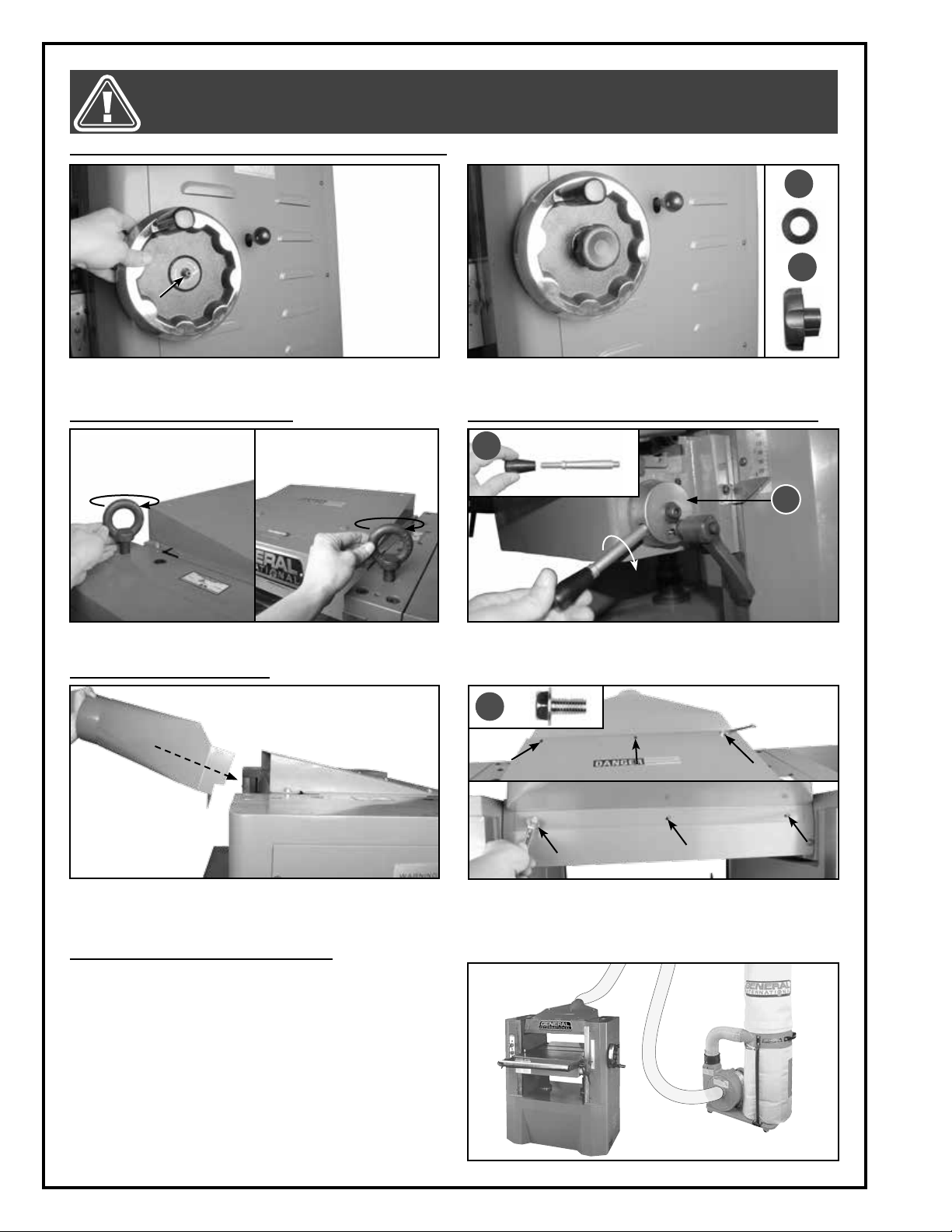
17. Keep guards in place and in working order. If a
guard must be removed for maintenance or clean-
ing make sure it is properly attached before using
the machine again.
18. Use of parts and accessories NOT recommended
by General®International may result in equipment
malfunction or risk of injury.
19. Never stand or lean on machinery. Serious injury
could result if the tool is tipped over or if the cutting
tool is unintentionally contacted.
20. Always disconnect the tool from the power source
before servicing or changing accessories such as
knives, or before performing any maintenance or
cleaning, or if the machine will be left unattended.
21. Make sure that the switch is in the “OFF” position be-
fore plugging in the power cord.
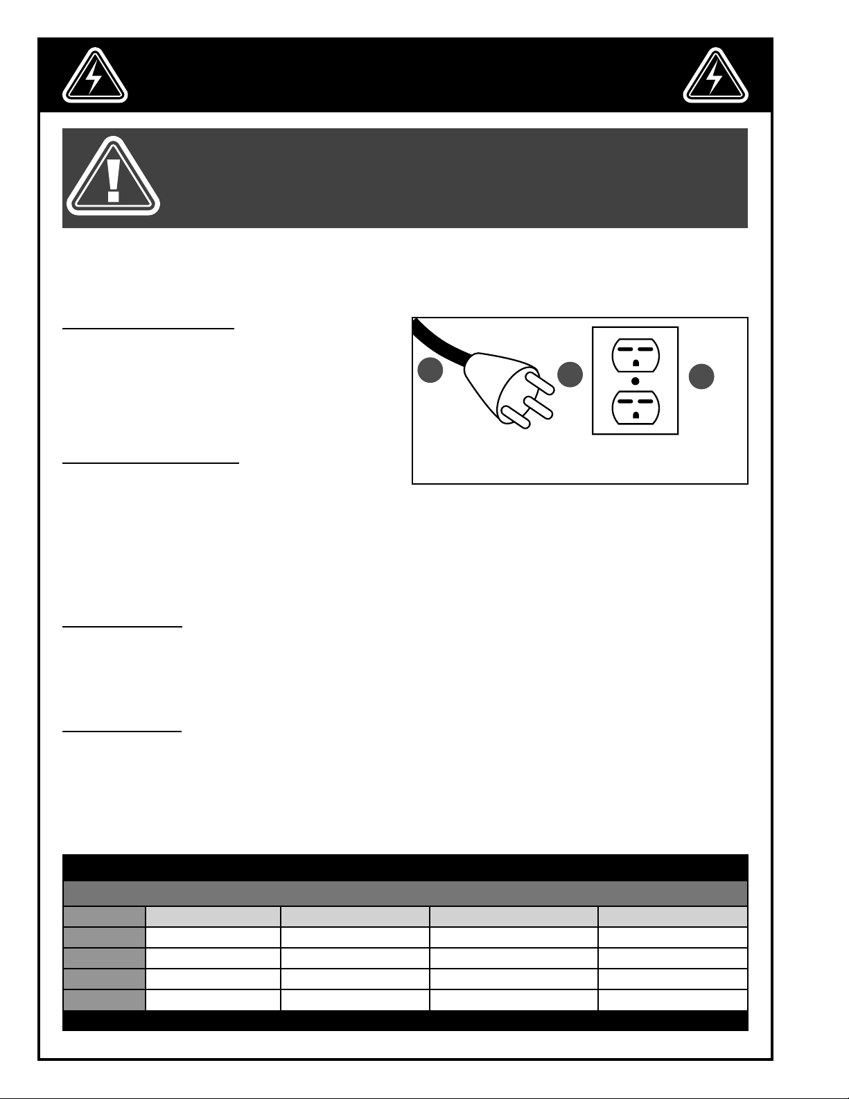
22. Make sure the tool is properly grounded.If equipped
with a 3-prong plug it should be used with a three-
pole receptacle. Never remove the third prong.
23. Do not use this planer for any purpose other than
its intended use. If used for other purposes, General®
International disclaims any real or implied warranty
and holds itself harmless for any injury, which may
result from that use.

ELECTRICAL REQUIREMENTS
6
BEFORE CONNECTING THE MACHINE TO THE POWER SOURCE, VERIFY THAT THE VOLTAGE OF YOUR POWER SUP-
PLY CORRESPONDS WITH THE VOLTAGE SPECIFIED ON THE MOTOR I.D. NAMEPLATE. A POWER SOURCE WITH
GREATER VOLTAGE THAN NEEDED CAN RESULT IN SERIOUS INJURY TO THE USER AS WELL AS DAMAGE TO THE
MACHINE. IF IN DOUBT, CONTACT A QUALIFIED ELECTRICIAN BEFORE CONNECTING TO THE POWER SOURCE.
THIS TOOL IS FOR INDOOR USE ONLY. DO NOT EXPOSE TO RAIN OR USE IN WET OR DAMP LOCATIONS.
ELECTRICAL CONNECTIONS
Both a manual circuit breaker (or similar device) as well
as an electrical plug (similar to the one shown) are re-
commended and SHOULD BE INSTALLED BY A QUALIFIED
ELECTRICIAN.
Use locally approved wire Athat includes a separate
grounding wire and a 3 prong grounding type plug B
with a matching receptacle C.
GROUNDING INSTRUCTIONS
In the event of an electrical malfunction or short circuit,
grounding reduces the risk of electric shock to the oper-
ator. The motor of the “M1” model of this machine is wired for 220 V single phase operation.As with many stationary
industrial type machines, because each installation situation is unique, this machine is supplied without a power
cord or plug.
The installation of an appropriate power cord and plug must be performed by a qualified electrician. The ma-
chine must be connected to an electrical source using a power cord that has a grounding wire, which must also
be properly connected to the grounding prong on the plug. The outlet must be properly installed and grounded
and all electrical connections must be made in accordance with all local codes and regulations.
CIRCUIT CAPACITY
Make sure that the wires in your circuit are capable of handling the amperage draw from your machine, as well as
any other machines that could be operating on the same circuit. If you are unsure, consult a qualified electrician.
If the circuit breaker trips or the fuse blows regularly, your machine may be operating on a circuit that is close to its
amperage draw capacity. However, if an unusual amperage draw does not exist and a power failure still occurs,
contact a qualified technician or our service department.
EXTENSION CORDS
The use of an extension cord is not generally recommended for 220 V equipment. If you find it necessary, use only
3-wire extension cords that have 3-prong grounding plug and a matching 3-pole receptacle that accepts the
tool’s plug. Repair or replace a damaged extension cord or plug immediately. Make sure the cord rating is suitable
for the amperage listed on the motor I.D. plate.
An undersized cord will cause a drop in line voltage resulting in loss of power and overheating. The accompanying
chart shows the correct size extension cord to be used based on cord length and motor I.D. plate amp rating. If in
doubt, use the next heavier gauge.
TABLE - MINIMUM GAUGE FOR CORD
EXTENSION CORD LENGTH
AMPERES 50 feet 100 feet 200 feet 300 feet
< 5 18 16 16 14
6 to 10 18 16 14 12
10 to 12 16 16 14 12
12 to 16 14 12 *NR *NR
*NR = Not Recommended
ABC
Note: voltage requirements and amperage draw for M2 & M3 3-phase motors may not be fully
described in this manual. For complete electrical requirements refer to the motor I.D. name
plate on the machine. If in doubt consult a licensed qualified electrician before proceeding.

7
IDENTIFICATION OF MAIN PARTS AND COMPONENTS
A. FRAME
B. EXTENSION ROLLER
C. ON/OFF SWITCH
D. MAIN TABLE
E. DUST CHUTE
F. GRADUATED SCALE
G. FEED SPEED ADJUSTMENT KNOB
H. DEPTH OF CUT ADJUSTMENT HANDWHEEL
I. ECCENTRIC BLOCK
J. EXTENSION ROLLER LOCK LEVERS (2)
K. TABLE ROLLER ADJUSTMENT LEVER
A
B
C
E
G
I
J
K
D
H
F

8
UNPACKING
BASIC FUNCTIONS
Carefully unpack and remove the unit and its components from the box and check for missing or damaged items
as per the list of contents below.
NOTE: PLEASE REPORT ANY DAMAGED OR MISSING ITEMS TO YOUR GENERAL® INTERNATIONAL DISTRIBUTOR IMMEDIATELY.
LIST OF CONTENTS QTY
A. DUST CHUTE ............................................................................. 1
B. HANDWHEEL (DEPTH OF CUT ADJUSTMENT).......................... 1
C. LIFTING HOOK ......................................................................... 2
D. FOOT PAD ................................................................................ 4
E. HANDLE (TABLE ROLLER ADJUSTMENT LEVER)....................... 1
F. THREADED ROD (TABLE ROLLER ADJUSTMENT LEVER)........... 1
G. LOCK KNOB (DEPTH OF CUT ADJUSTMENT HANDWHEEL).... 1
H. FLAT WASHER (DEPTH OF CUT ADJUSTMENT HANDWHEEL)... 1
I. FLANGE BOLT (DUST CHUTE)................................................... 6
J. SCREWDRIVER ......................................................................... 1
K. 3, 4, 6 MM ALLEN KEYS............................................................ 1
L. 10,14,19, 24 MM WRENCHES .................................................. 1
M. KNIFE SETTING BAR* ................................................................ 1
N. KNIFE SETTING PAD* ................................................................ 2
O. RETENTION RING* ................................................................... 4
A
B
C
D
KL
KNIFE SETTING JIG*
M
N O
E
F
J
G
H I
ADDITIONAL REQUIREMENTS FOR SET UP
A. 0,02” FEELER GAUGE
B. 0,004” FEELER GAUGE
C. GAUGE BLOCK
D. STRAIGHT EDGE
B
AD
0.0
2
”
0
.0
0
4
”
C
This 20” heavy-duty planer is designed for thickness planing of solid wood only. The unit is not designed nor should
it be used to surface or prepare, plywood, wood paneling, particleboard, MDF nor any other wood based by-
products nor any non-wood based materials.
This unit has the capacity to plane boards of up to 20” wide having a maximum thickness of 8” and a minimum
thickness of 3/16”.
The unit is offered with 2 different cutter head options as follows:
• Model 30-360 M1 – 20” planer with 4-knife cutter head;
• Model 30-360HC M1 - 20” planer with General International’s unique “Magnum” style helical cutter head con-
taining 58 reversible two-sided, quick-change carbide inserts.
*Not included and not needed for 30-360HC

9
PLACEMENT WITHIN THE SHOP / SAFETY ZONE
The protective coating on the table prevents rust from
forming during shipping and storage. Remove it by
rubbing with a rag dipped in kerosene, mineral spirits
or paint thinner. (Dispose of potentially flammable sol-
vent-soaked rags according to manufacturer’s safety
recommendations).
A putty knife, held flat to avoid scratching the surface,
may also be used to scrape off the coating followed
by clean-up with solvent. Avoid rubbing the machine’s
painted surfaces, as many solvent-based products will
remove paint.
To prevent rust, apply a light coating of paste wax or
use regular applications of any after-market surface
protectant or rust inhibitor.
CLEANING
PLACEMENT WITHIN THE SHOP
This machine should be installed and operated only
on a solid, flat and stable floor that is able to support
the weight of the machine (1397 lbs - 635 kg) and the
operator. Using the dimensions shown as a guideline,
plan for placement within your shop that will allow the
operator to work unencumbered and unobstructed by
foot traffic (either passing shop visitors or other shop
workers) or other tools or machinery.
ESTABLISHING A SAFETY ZONE
For shops with frequent visitors or multiple operators,
it is advisable to establish a safety zone around shop
machinery. A clearly defined “no-go” zone on the floor
around each machine can help avoid accidents that
could cause injury to either the operator or the shop
visitor. It is advisable to take a few moments to either paint (using non-slip paint) or using tape, define on the floor
the limits or perimeter of each machines safety zone. Take steps to ensure that all operators and shop visitors are
aware that these areas are off limits whenever a machine is running for everyone but the individual operating the
unit.
36"
22"
48"
KNIFE SETTING JIG*
1. Using a pair of pliers, push a retention ring into the
inner grooves on each end of the knife setting jig
rod as shown A.
2. Slide one foot onto one end of the rod as shown B.
3. Secure the foot on the rod by pushing a retention
ring into the exposed groove in the rod as shown
C.
4. Repeat step 2 and 3 to install the other foot as
shown D. Set the jig aside for use whenever knife
settings need to be verified or adjusted.
ASSEMBLY INSTRUCTIONS
D
B
A
C
*Not included and not needed for 30-360HC

10
BEFORE ASSEMBLING, MAKE SURE THAT THE SWITCH IS IN THE “OFF” POSITION AND THAT THE POWER CORD IS
UNPLUGGED. DO NOT PLUG IN OR TURN ON THE MACHINE UNTIL YOU HAVE COMPLETED THE ASSEMBLY AND
INSTALLATION STEPS DESCRIBED IN THIS SECTION OF THE MANUAL.
ATTACH THE DEPTH OF CUT ADJUSTMENT HANDWHEEL
1. Slide the handwheel onto the arbor. 2. Slide the flat washer Aonto the arbor, then secure
it in place with by tightening the lock knob B.
A
B
CONNECTING TO A DUST COLLECTOR
A dust chute that fits 5” hose is provided to accommo-
date connection to a dust collector (not included). Be
sure to use appropriate sized hose and fittings (not in-
cluded).
Check that all connections are sealed tightly to help
minimize airborne dust. If you do not already own
a dust collection system consider contacting your
General® International distributor for information on
our complete line of dust collection systems and ac-
cessories or visit our Web Site at www.general.ca.
1. Place the dust chute against the opening in the
back of the machine.
2. Align the mounting holes in the dust chute with the
corresponding holes in the machine, then secure
it with 6 flange bolts Eusing a 10 mm wrench.
INSTALLING THE DUST CHUTE
INSTALLING THE LIFTING HOOKS INSTALLING THE TABLE ROLLER ADJUSTMENT LEVER
If needed,install the lifting hooks on the top of the machine. Tighten the handle onto the shaft C, then tighten the
assembly into the bracket D.
D
C
E

11
BASIC ADJUSTMENTS & CONTROLS
TO REDUCE THE RISK OF SHOCK OR FIRE DO NOT OPERATE THE UNIT WITH A DAMAGED POWER CORD OR PLUG. RE-
PLACE DAMAGED CORD OR PLUG IMMEDIATELY. TO AVOID UNEXPECTED OR UNINTENTIONAL START-UP, MAKE SURE
THE POWER SWITCH IS IN THE OFF POSITION BEFORE CONNECTING TO A POWER SOURCE.
CONNECTING TO A POWER SOURCE
Once the assembly steps have been completed, plug
the power cord into an appropriate outlet.
Refer back to the section entitled “Electrical Require-
ments” and make sure all requirements and grounding
instructions are followed.
When operations have been completed unplug the
machine from the power source.
MAGNETIC SAFETY SWITCH
This machine is equiped with a magnetic safety switch
designed to protect the the user from unintentional start-
up.The switch assembly is equipped with a GREEN“START”
button Aand a RED spring loaded “STOP” button B.
Once the RED “STOP” button has been pressed, the ma-
chine can only be restarted by turning the inner part of
the button to the right to release the stop button, C.
C
A
B
SWITCH OFF
TO AVOID UNEXPECTED OR UNIN-
TENTIONAL START-UP, MAKE SURE
THAT THE POWER SWITCH IS IN
THE OFF POSITION BEFORE CON-
NECTING TO A POWER SOURCE.
OVERLOAD PROTECTION
The magnetic safety switch on this machine is equipped with an overload protection feature. To prevent an elec-
trical overload from damaging the motor, in the event of a spike in line voltage or amperage draw, the internal
overload protector will automatically be tripped, thereby cutting off power to the motor.
Common causes of such overloads:
• Overworking the motor by forcing the machine, particularly with thicker denser material, thereby causing an
increase in power consumption and a spike in amperage draw.
• An electrical extension cord that is too long or not the correct gauge of wire, which can also cause an in-
crease in amperage draw. If an electric extension cord must be used, follow the instructions and refer to the
chart in the electrical requirements section at the beginning of this manual.
• Overworked circuit caused by operating on a circuit that is close to its amperage draw capacity. Make sure
thecircuit being used is capable of handling the amperage draw from this machine as well as any other elec-
trical devices operating on the same circuit. If you are unsure, consult a qualified electrician.
1. Unplug the machine. Open the motor door in the
back of the machine and remove electrical box
cover a Phillips screwdriver.
2. Press the button Dto reset the overload protection.
Before to start the machine, retighten the cover box
and close the motor door.
To reset the overload protection switch after it has been tripped proceed as follows:
D

12
ADJUSTING TABLE ROLLER HEIGHT
MAKE SURE THE MACHINE HAS BEEN TURNED OFF AND UNPLUGGED FROM THE POWER SOURCE BEFORE PERFORM-
ING ANY MAINTENANCE OR ADJUSTMENTS.
The two adjustable table rollers Aare designed to help
reduce friction when feeding stock through the planer.
The height of the rollers can be set based on personal
preference as well as the type of stock being fed into
the machine.
As a general rule when planing rough stock the rollers
should be set higher, and when planing smooth stock
they should be set lower.
To adjust the height of the table rollers:
1. Loosen the lock lever Band then turn the adjust-
ment lever Cup or down as needed. Tighten the
lock lever Bto secure the rollers at the desired
height.
C
B
A
IMMOBILIZING THE MACHINE
G
F
Machine vibration during operation may cause the
machine to move, particularly when installed on un-
even surfaces.
The pads Fand anchor bolts Gcan be used to help
keep the machine immobilized by either lowering the
bolts against pads on the floor to act as points of con-
tact with the floor, or for permanent installations, by drill-
ing into the floor and bolting the machine in place.
USING THE TABLE EXTENSION ROLLER
The infeed table extension roller is designed to support the workpiece as well as to help reduce friction when feed-
ing longer stock through the planer.
1. Loosen the levers (right & left) D, then lift the table
extension into the horizontal position and push it all
the way. Tighten the levers Dto lock the roller in po-
sition.
Note: Make sure the extension roller plates are against the
eccentric nuts E.
DE

13
OPERATING INSTRUCTIONS
BASIC PRINCIPLES OF PLANING
ALWAYS PLANE IN THE GENERAL DIRECTION OF THE GRAIN. PLANING AGAINST THE GRAIN OR PLANING END GRAIN
IS DANGEROUS AND MAY CAUSE THE WORKPIECE TO SHATTER.
This planer is designed to remove material from the top
face of a board in order to bring the board (or a series
of boards) down to a specific desired shape or profile
and thickness.
To obtain uniform results across the length of a board,
the stock being planed must have one face that has
already been machined perfectly flat (usually on a
jointer) and the stock should be fed with this flat face
against the table. FLAT SIDE DOWN
SELECTING BOARDS SUITABLE FOR PLANING
This planer is intended for use with solid woods or MDF
only, and should not be used to plane or mold any
other materials. The workpiece should always be fed
through the machine in the general direction of the
grain in the wood. Before being fed through the planer
all lumber should be inspected for debris and foreign
objects such as staples or nails.
Foreign objects stuck to, or embedded in your work-
piece can be ejected from the machine at high speed
and cause serious injury or damage cutter knives.
Make sure to remove all such foreign objects from
the wood before running it through the planer. Select
lumber carefully and avoid workpieces with loose or
protruding knots. Workpieces that are twisted, severely
deformed or warped should also be avoided.
Warped, twisted, damaged or fragile stock runs an increased risk of jamming in or damaging the machine or cut-
ters. There is also a much greater risk of injury to the operator or bystanders from kickback, where the workpiece is
forcefully or violently ejected from the machine due to a jam, whenever working with such damaged or warped
wood.
GRAIN DIRECTION
GRAIN DIRECTION
GRAIN DIRECTION
GRAIN DIRECTION
Max. 20”
Max. 8”
Min. 3/16”
Min. 8 1/4”
Maximum planing width: 20”
Maximum workpiece thickness: 8”
Minimum workpiece thickness: 3/16”
Minimum workpiece length: 8 1/4”
RESPECT THE RATED LIMITS OF THIS MACHINE IGNORING THESE LIMITS AND FEEDING NON COMPATIBLE STOCK INTO
THIS PLANER CAN LEAD TO SERIOUS INJURY TO THE USER OR SHOP BYSTANDERS, AND CAUSE DAMAGE TO THE WORK-
PIECE AND/OR THE MACHINE. IF THE STOCK YOU WISH TO PLANE DOES NOT MEET OR COMPLY WITH THE LIMITATIONS
LISTED ABOVE, FIND ANOTHER SAFER WAY TO PERFORM THE REQUIRED TASK.
RATED LIMITS OF THIS PLANER

14
CHECKLIST BEFORE STARTING
• Make sure the board has been inspected and is suitable for planing as explained in section “Selecting boards
suitable for planing”.
• Make sure you and any assistants are wearing safe appropriate workshop attire. Roll up long sleeves, secure
long hair and remove any jewelry: watches, rings, bracelets or anything that could become caught in the mov-
ing parts, potentially causing serious injury.
• Make sure to have on safety glasses as well as hearing and respiratory protection at all times when using the
planer.
• To reduce the risk of damage to the planer or the workpiece, as well as a potential for personal injury, after initial
set-up as well as before each use, make sure that everything is securely installed and that all fasteners and mov-
ing parts on this machine are locked in place before starting the machine.
• If multiple boards are to be planed, collect all workpieces together and set them nearby on a table or bench
within easy reach D. To limit the potential for injury in the event of a kickback, avoid having to step or reach in
front of the machine to pick up the next workpiece E.
DE
AVOID HAVING TO STEP
OR REACH IN FRONT OF
THE MACHINE!
ADJUSTING THE DEPTH OF CUT
The depth of cut is adjustable by using the handwheel
A. Remind that the maximum depth of cut on full
width planing is 1/8” and lowering the head assem-
bly. It is recommended that for both hard and soft wood:
removing less material per pass and taking multiple
passes is always preferred to more aggressive planing.
1. turn off the machine.
2. Position the board under the infeed roller and ad-
just the position of the table work with the hand-
wheel Aso that the infeed roller is in contact with
the board.
3. Remove the board and adjust the cutting depth us-
ing the scale Bby turning the handwheel Aclock-
wise.
B
A
ADJUSTING FEED SPEED
Two rollers turn and feed the stock. The feed motor
speed ranges from 22 to 28 fpm (feet per minute). The
feed speed adjustment knob is located on the right
hand side of the machine.
Select appropriate feed speed for the stock being
plane: high speed for softwood and slow for hardwood.
Experiment with feed speeds based on the workpiece
material and its width as well as the depth of cut, to find
which setting work best for your needs.
- To increase the feed rate at 28 fpm, pull the knob C
out.
- To decrease the feed rate at 22 fpm, push the knob
Cback.
- For zero speed, set the knob Cin neutral position.
22 fpm
0
28 fpm
NOTE: TO AVOID DAMAGE TO THE GEARBOX, SPEED CHANG-
ES SHOULD ONLY BE MADE WHILE THE MACHINE IS RUNNING.
C

15
PLANING STEP-BY-STEP
1. With the planer turned off, position the workpiece
on the infeed table with the flat face down and the
face to be planed facing up.
2. Adjust the depth of cut A(see section “Adjusting
depth of cut).
5. Align the board laterally so that it will be fed through
the planer in the general direction of the grain, and
allow the workpiece enough clearance to feed
properly without rubbing or catching on either side
of the machine.
6. Slowly slide the workpiece forward until the infeed
roller “grips” the board.
7. Release the board allowing the feed roller to auto-
matically feed the board through the planer.
8. Step to the rear of the machine and recover the planed
board on the outfeed table once it has cleared the
outfeed roller and has stopped advancing.
GRAIN DIRECTION
GRAIN DIRECTION
GRAIN DIRECTION
GRAIN DIRECTION
NEVER PUSH, PULL OR OTHERWISE TRY TO MOVE OR RE-
POSITION THE WORKPIECE ONCE IT IS IN THE CONTROL
OF THE AUTOMATIC FEED ROLLERS.
A
22 fpm
0
28 fpm
3. Set the board aside, then turn the planer on B. Ad-
just the speed.
4. Stand to one side of the machine and set the board
back on the infeed table with the face to be planed
facing up.
TO LIMIT THE POTENTIAL FOR INJURY IN THE EVENT
OF A KICKBACK, AVOID STANDING DIRECTLY IN LINE-
WITH THE FRONT OR BACK OF THE PLANER WHENEV-
ERA BOARD IS ENGAGED IN THE CUTTER HEAD.
B

Note: It is recommended to verify the following before starting any new project. To do this will require: A straight edge, a
feeler gauge, a gauge block (see below).
45°
2"
4"
4"
3"
1/4"
1/2"
1/2"
1½"
GAUGE BLOCK
You may use a home made gauge block made of hardwood. The gauge block can be made by follow-
ing the dimensions in the illustration. If you prefer, precision aluminum gauge blocks are available from
General International under item #30-040.
MAKE SURE THE MACHINE HAS BEEN TURNED OFF AND UNPLUGGED FROM THE POWER SOURCE BEFORE PERFORM-
ING ANY MAINTENANCE OR ADJUSTMENTS.
ADJUSTING CUTTER HEAD PARALLEL TO THE TABLE
The cutter head has been pre-set parallel to the table at the factory, therefore, except in some rare cases (impor-
tant maintenance, transport handling) no further adjustments are required.
If adjustments are required follow these procedures:
1. Disconnect the machine from the power source.
2. Place the gauge block Aon table directly under cutter head. Lower the cutter head until the it just touches the
gauge block A.
3. Move the gauge block Ato opposite end of the table and make sure it just touches the cutter head at the
other end as well.
If not, leave the gauge in place and follow the instructions below.
4. Under the table, loosen the three screws Busing the a 6 mm Allen key, insert a screwdriver in the hole located
in the lead screw housing C, and then turn the shaft clockwise or counterclockwise so that the gauge block A
just touches the cutter head.
5. Position the gauge block Ato the other side to make sure the table is now parallel to the cutter head and
retighten the bolts B.
A
B
C
MAINTENANCE
16

MAKE SURE THE MACHINE HAS BEEN TURNED OFF AND UNPLUGGED FROM THE POWER SOURCE BEFORE PERFORM-
ING ANY MAINTENANCE OR ADJUSTMENTS.
ADJUSTING THE INFEED & OUTFEED ROLLERS
1. Begin by take note of all the components in order
to make required adjustments: Ainfeed roller; B
chipbreaker; Ccutter head with knife/insert; Dout-
feedroller.
2. Place the gauge block Eunder the knife/insert C,
adjust the table height until you can only slide a
0.02” feeler gauge Fbetween the block and the
cutter. Once finished, do not move the height of the
table.
A B CDE
0.0
2
”
F
ADJUSTING THE CHIPBREAKER
3. Place the block Eunder the end of the infeed roller
Aas shown. Loosen the nut G, turn the screw Huntil
the roller touches the top of the block, and then re-
tighten the nut G. Repeat for the other end.
4. Place the block Eunder the end of the outfeed
roller D. Loosen the nut I, turn the screw Juntil the
roller touches the top of the block, and then re-
tighten the nut I. Repeat for the other end.
E
E
G
H
I
J
1. Place the block Eunder a knive/insertion and ad-
just the table height until you can slide only a 0,004”
feeler gauge Kbetween the block Eand the knive/
insertion. Then place the block under the chip-
breaker B.
E
0
.0
0
4
”
K
2. Remove the dust chute, remove the two bolts Lwith
a 10 mm wrench, and then lift the chip deflector
cover in order to access the cutter head.
LL
LEFT SIDE RIGHT SIDE
REAR VIEW
REAR VIEW
17

3. Loosen the two jam nuts Musing a 10 mm wrench.
4. Turn the set screws Nusing a 4 mm Allen key in the
direction required so that the chipbreaker (see ref-
erence Bin a previous page) touches the top of
the block.
Note: Start with the set screw N located on the same side
as the gauge block, then move the block to the other end
and adjust the other set screw.
5. Retighten the two jam nuts using a 10 mm wrench.
Re-install the chip deflector and the dust chute be-
fore starting the machine.
MAKE SURE THE MACHINE HAS BEEN TURNED OFF AND UNPLUGGED FROM THE POWER SOURCE BEFORE PERFORM-
ING ANY MAINTENANCE OR ADJUSTMENTS.
1. Disconnect the machine from the power source.
Place a straight edge across the rollers A in up po-
sition.
2. Using a 10 mm wrench, loosen the jam nuts Blo-
cated at each end table roller under the table, then
turn the bolts Cto the direction required to raise or
lower the roller. Retighten the bolts Band repeat
with the other roller.
Note: Always make sure the rollers are parallel to the table
and at the same height.
The table rollers are set parallel at the factory and under normal circumstances should not require alignment
upon initial installation. However with use over time, it may become necessary to re-align the rollers.
If so proceed as follows:
ALIGNING THE TABLE ROLLERS
M
N
D
C
B
A
ADJUSTING THE CHIPBREAKER (CONTINUED)
LEVELING THE EXTENSION ROLLER TO THE TABLE ROLLERS
1. Place a straight edge across the table rollers and
the extension roller in up position.
2. Verify visibly that the extension roller is leveled to
the table rollers.
To level:
3. Loosen two eccentric blocks using a 4 mm Allen
key, then turn the eccentric blocks in the direction
required until the extension roller is leveled to the
table rollers.
18

19
MAKE SURE THE MACHINE HAS BEEN TURNED OFF AND UNPLUGGED FROM THE POWER SOURCE BEFORE PERFORM-
ING ANY MAINTENANCE OR ADJUSTMENTS.
PERIODIC MAINTENANCE
• Inspect/test the ON/OFF switches before each use. Do not operate the planer with a damaged switch; replace
a damaged switch immediately.
• Keep the machine as well the table clean and free of saw dust, woodchips, pitch or glue.Vacuum or brush off
any loose debris and wipe down the machine and the table occasionally with a damp rag.
• An occasional light coating of paste wax can help protect the table surface and reduce workpiece friction.
Ask your local distributor for suggestions on aftermarket surface cleaners, protectant and dry lubricants based
on what is readily available in your area.
• Avoid using silicon based products that may affect or react with wood finishing products such as oil, solvent or
water-based stains, varnishes and lacquers.
• Periodically inspect the power cord and plug for damage. To minimize the risk of electric shock or fire, never
operate the planer with a damaged power cord or plug. Replace a damaged power cord or plug at the first
visible signs of damage.
• The drive gears, chain and elevation screws should be cleaned of woodchips, dust, debris and old grease.
After cleaning, re-apply a generous coating of any common automotive bearing grease.
• Regularly inspect planed workpieces for signs of knife/inserts damage or wear and replace damaged or
worn knives immediately.
• Wipe the chains with a lubricated cloth for medium to slow speed operation.
• If excessive build-up of dust, dirt or wood shavings occur ; coat chain with a light film of oil (never pour directly
on chain). Over oiling defeats the purpose of the lubrication, the chain will overly accelerate , and will require
constant replacement.
• The bearings on the cutter head are factory lubricated and sealed, therefore they require no further attention.
INSPECTING CUTTER HEAD KNIVES/INSERTS
Cutter head knives (blades)/inserts are installed in the
planer at the factory. With usage and normal wear over
time, it will eventually become necessary to replace
the knives, or to reverse the inserts if applicable. When
needed, replacement knives (sold in sets of 3) or inserts
(sold in sets of 10) can be ordered through your local
General International distributor under part #30-362
or #30-364 (for model 30-360) or 30-443 (for model 30-
360HC). Observing planed workpieces as they come
out of the machine and looking for signs of knife dam-
age or wear is the best method to help you to deter-
mine when knives/insertions are due to be changed.
Signs to look for include:
1. A raised ridgeline in the workpiece that runs a
straight line from beginning to end of the board A.
This is generally an indication that one or all of the
knives/inserts has been nicked or damaged by a
for-eign object such as a nail, staple or other hard
ob-ject hidden or embedded in the workpiece.
2. A slight washboard or chatter effect, B, which can
be an indication of uneven knife wear/insertions or
causing one knife/several inserts to cut just deeper than the other.
3. Rough, irregular, torn or fuzzy grain on a freshly planed surface may be a sign of worn or dull blades/inserts
causing the wood to tear out. Sharp blades cut crisply and leave a relatively smooth finish.
Note: fuzzy grain can also be a sign of high moisture content in the workpiece. If knives have recently been changed or
if you suspect that moisture content and not dull knives is the cause, set the workpiece aside and test by planing other
boards with known or acceptable moisture content. If the planed results using a different workpiece are smooth, then
moisture content in your wood is the problem - no adjustments can be made to the machine for this. Set the “wet” stock
aside and simply work with drier wood. To maintain even knife wear always replace all knives each time knife replace-
ment is required (only for the model 30-360).
EFFECT EXAGGERATED FOR CLARITY
B
A

20
MAKE SURE THE MACHINE HAS BEEN TURNED OFF AND UNPLUGGED FROM THE POWER SOURCE BEFORE PERFORM-
ING ANY MAINTENANCE OR ADJUSTMENTS.
INSPECTING CUTTER HEAD KNIVES (MODEL 30-360 ONLY)
Note: To make sure the knives are properly adjusted, use the jig provided to check each of the four knives.
1. Unscrew the 6 screws and remove the left panel us-
ing a 4 mm Allen key.
2. Remove the dust chute and the chip deflector bolts
Ausing a 10 mm wrench. Then tilt up the chip de-
flector cover.
A A
3. Remove the chip deflector using a 4 mm Allen key. 4. Position one of the four knives on top by manually
turning the cutter head belt and setting the gauge
Bon the cutter head as shown C.
RIGHT SIDE
LEFT SIDE
B
Ideal knife position has the gauge sitting flush on the cutter head and the knife barely touching the center refer-
ence pads on the gauge D.
Make sure the other knives are positioned properly and in a good condition. Should any (or all) of the knives need
adjusting, follow the instructions in the section “Knife setting or replacement”. Once the verifications are done, re-
install the chip deflector, chip deflector cover and the left panel before starting the machine.
C
D
This manual suits for next models
1
Table of contents
Other General Planer manuals