Maier 220 User manual

Bedienungsanleitung
Operating instructions
Manuel d´instructions
Instrucciones de servicio
220, 221, 240, 241, 251, 261,
271, 281, 252, 352

2
Contents
Index
GB
Manufacturer's Declaration…………………………………………………………………………………………………...3
General notes.......................................................................................................................................................... 5
Directives ............................................................................................................................................................ 5
Safety notes........................................................................................................................................................ 5
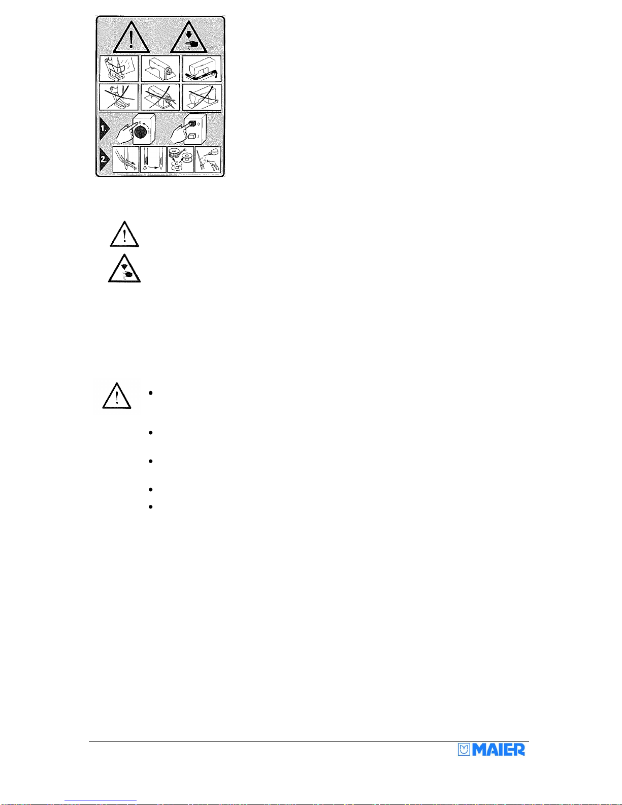
Safety symbols.................................................................................................................................................... 6
Items requiring the Operator's special attention.................................................................................................. 6
Operators and specialist staff.............................................................................................................................. 7
Operators............................................................................................................................................................ 7
Specialist staff..................................................................................................................................................... 7
Hazard warnings................................................................................................................................................. 8
Transport, packaging and storage....................................................................................................................... 8
Installation and initial commissioning.................................................................................................................. 8
Care of the machine............................................................................................................................................ 8
Disposal of the machine...................................................................................................................................... 9
Assembly of the machine ...................................................................................................................................... 10
Installation instructions...................................................................................................................................... 10
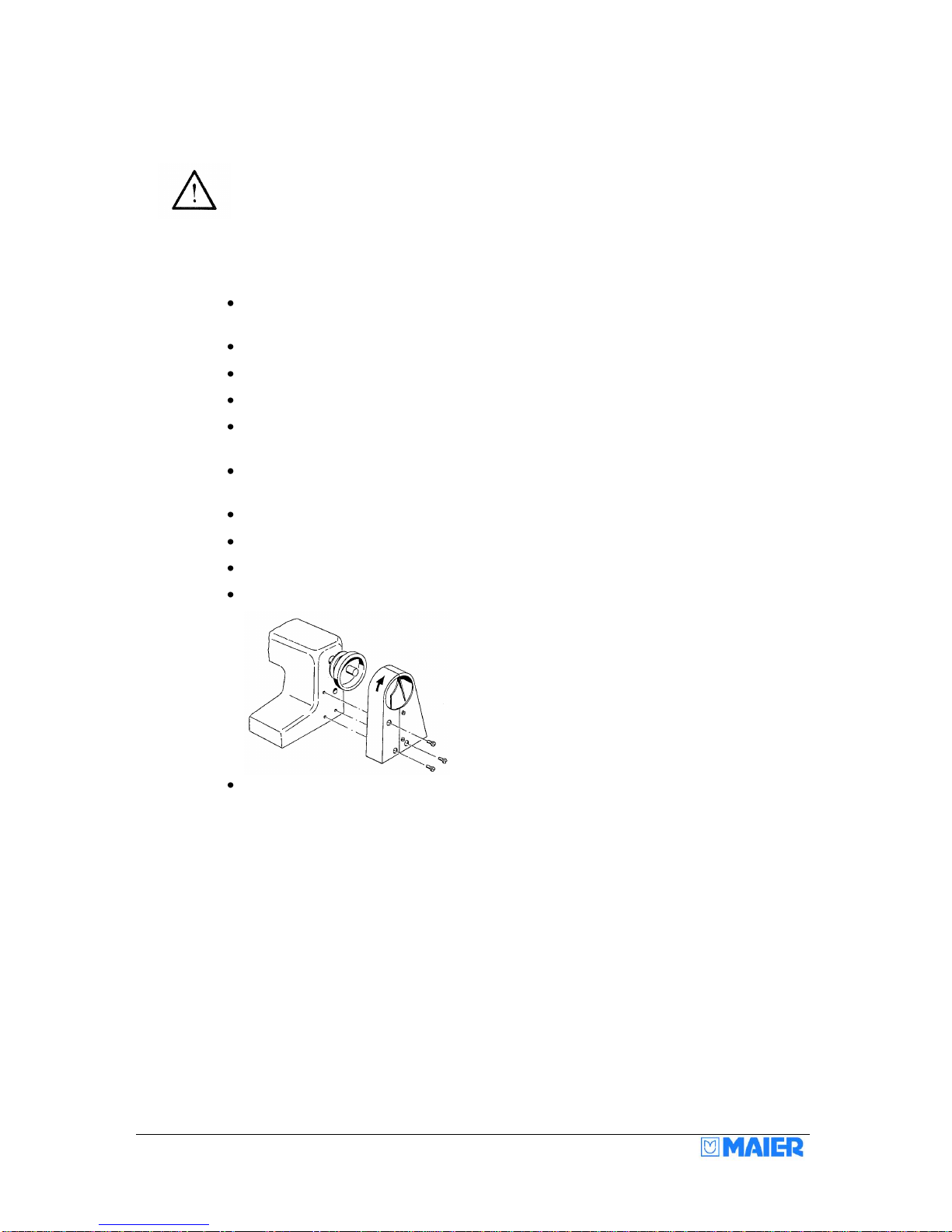
Mounting instructions for the mini-motor 46 attachment kit............................................................................... 11
Classes 221 /241/ 251 / 261 /271 ................................................................................................................. 11
Classes 252/352........................................................................................................................................... 11
Automatic frame drop device............................................................................................................................. 12
Accessories:...................................................................................................................................................... 12
Sewing machine table tops ............................................................................................................................... 13
Operation............................................................................................................................................................... 15
Threading.......................................................................................................................................................... 15
Machine without thread cutter (Fig. 1) .......................................................................................................... 15
Machine with thread cutter (Fig. 2) ............................................................................................................... 15
Inserting the cloth and sewing........................................................................................................................... 16
Blind stitch hems on the hem edge............................................................................................................... 16
Blind stitch hems on the cloth tuck................................................................................................................ 16
Setting the stitch depth (penetration) ................................................................................................................ 18
Classes 220, 221, 240, 241, 251, 261, 271 .................................................................................................. 18
Classes 252 and 352.................................................................................................................................... 19
Setting the cloth retainers for classes 251, 261, 271, 281, 252, 352................................................................. 21
Setting the helical spring................................................................................................................................... 21
Fitting the needle............................................................................................................................................... 22
Checking the needle motion ......................................................................................................................... 22
Skip stitch device .............................................................................................................................................. 23
Instructions for the mechanic................................................................................................................................. 24
Setting the stitch plate....................................................................................................................................... 24
Basic setting of the needle movement .............................................................................................................. 25
Fitting and checking the looper ......................................................................................................................... 25
Adjusting the looper .......................................................................................................................................... 26
Adjusting the height of the looper ................................................................................................................. 26
Adjusting the lateral position of the looper.................................................................................................... 26
Adjusting the looper stroke ........................................................................................................................... 27
Setting the thread take-up cam......................................................................................................................... 27
Stitch length adjustment.................................................................................................................................... 28
Plunger (rib shaft) adjustment........................................................................................................................... 29
Radial position.............................................................................................................................................. 29
Axial position................................................................................................................................................. 29
Play............................................................................................................................................................... 30
Setting the plunger (rib shaft) timing............................................................................................................. 30
Plunger (rib shaft) skip stitch timing.............................................................................................................. 30
Feed dog adjustment ........................................................................................................................................ 31
Sewing faults and how to remedy them ............................................................................................................ 32
Sewing tools.......................................................................................................................................................... 33
Technical data....................................................................................................................................................... 34

3
D
Herstellererklärung
Im Sinne der EG-Maschinenrichtlinie
89/392/EWG Anhang II B
Hiermit erklären wir, dass die Bauart der MAIER-
Blindstichnähmaschine (Nähmaschinenoberteil)
Klasse und Seriennr. (siehe Typenschild)
zum Einbau in eine Näheinheit oder Nähanlage
bestimmt ist und dass ihre Inbetriebnahme solange
untersagt ist, bis festgestellt wurde, dass die
Näheinheit oder Nähanlage, in die dieses
Nähmaschinenoberteil eingebaut werden soll, den
Bestimmungen der EG-Maschinenrichtlinie entspricht.
Angewendete harmonisierte Normen, insbesondere:
EN 292-1, EN 292-2, EN 60204-3-1
EG-Konfirmitätserklärung
Im Sinne der EG-Maschinenrichtlinie
89/392/EWG Anhang II A
Hiermit erklären wir, dass die Bauart der Näheinheit
bzw. –anlage MAIER-Blindstichnähmaschine
Klasse und Seriennr. (siehe Typenschild) folgenden
einschlägigen Bestimmungen entspricht:
EG-Maschinenrichtlinie 89/392/EWG, zuletzt geändert
durch 93/44/EWG, Anhang I Nr. 1
EG-Niederspannungsrichtlinie 73/23/EWG
EG-Funktionsstörungsrichtlinie 87/308/EWG
Angewendete harmonisierte Normen, insbesondere:
EN 292-1, EN 292-2, EN 60204-3-1
GB
Manufacturer´s Declaration
In accordance with the EC Machinery Directive
89/392/EC, Annex II B
We hereby declare that the MAIER-Blindstitch Sewing
Machine (sewing machine head)
Class and Serial No. see rating plate, must be
incorporated into a sewing unit or sewing system and
that it must not be put into service until the sewing
unit or sewing system into which this sewing machine
is to be incorporated has been declared in conformity
with the provisions of the EC Machinery Directive.
Applied harmonised standards, in particular:
EN 292-1, EN 292-2, EN 60204-3-1
EC Conformity Declaration
In accordance with the EC Machinery Directive
89/392/EC, Annex II A
We hereby declare that the sewing unit or sewing
system MAIER-Blindstitch Sewing Machine
Class and Serial No. see rating plate, complete with
sewing stand and motor (see rating plate) complies
with the following applicable regulations:
EC Machinery Directive 89/392/EEC, last amended by
93/44/EEC, Annex I No. 1
EC Low Voltage Directive 73/23/EEC
EC Radio Frequency Interference Directive
87/308/EEC
Applied harmonised standards, in particular:
EN 292-1, EN 292-2, EN 60204-3-1
F
Declaration du fabricant
au sens de la directive CE sur les machines
89/392/CEE, annexe II B
Nous déclarons que la tête couseuse de la MAIER-
Machine à coudre à points invisibles (tête couseuse)
Classe et no. de série voir plaque est destinée à être
incorporée dans une unité ou une installation de
couture et que sa mise en service est interdite jusqu’à
ce que la conformité de cette unité ou de cette
installation de couture aux dispositions de la directive
CE sur les machines ait été constatée.
Normes appliquées après harmonisation, notament:
EN 292-1, EN 292-2, EN 60204-3-1
Declaration de Conformite CE
au sens de la directive CE sur les machines
89/392/CEE, annexe II A
Nous déclarons la conformité de l’unité ou
l’installation de couture MAIER-Machine à coudre à
points invisibles Classe et no. de série voir plaque
equipé de table à coudre et moteur (voir plaque) aux
prescriptions correspondentes ci-après:
directive CE sur les machines 89/392/CEE, dernière
actualisation
effectué par 93/44/CEE, annexe I no. 1
directive CE sur la basse tension 73/23/CEE
directive CE sur l’interference radio 87/308/CEE
Normes appliquées après harmonisation, notament:
EN 292-1, EN 292-2, EN 60204-3-1
E
Declaratión del fabricante
de conformidad con la directiva CE sobre máquinas
89/392/CEE, Anexo II B
Por la presente declaramos que el tipo de Máquina
de puntada invisible MAIER (parte superior de
máquina) Clase y número de serie vease placa
indicadora está destinada a ser montada en una
unidad de costura o instalación de costura, debiendo
comprobarse ants de su montaje que la unidad de
costura o instalación de costura en la que dicho
cabezal debe instalarse, cumple con las
disposiciones de la Directiva sobre máquinas CE.
Normas armonizadas utilizadas, especialmente:
EN 292-1, EN 292-2, EN 60204-3-1
Declaratión de conformidad
de conformidad con la directiva CE sobre máquinas
89/392/CEE, Anexo II A
Por la presente declaramos que el tipo de unidad de
costura e instalación de costura de Máquina de
puntada invisible MAIER Clase y número de serie
vease placa indicadora compl. con mesa de coser y
motor (vease placa indicadora) corresponde a las
disposiciones siguientes:
directiva CE sobre máquinas 89/392/CEE, modificada
últimamente por 93/44/CEE, Anexo I No. 1
directiva CE sobre baja tensión 73/23/CEE
directiva CE sobre radio interferencia 87/308/CEE
Normas armonizadas utilizadas, especialmente:
EN 292-1, EN 292-2, EN 60204-3-1

4
With this machine, you have acquired a user-friendly, universal and robust high-
performance blind stitch sewing machine. All important information relating to working
with this machine and the various setting possibilities is provided on the following
pages. If you need further information, or have any difficulties whatsoever, please
contact your trusted dealer. Of course, apart from this, we - as the manufacturer - are
ready to answer your questions at any time, and to help you with any problems you
may have. In this case, please write direct to us or telephone us.
Maier-Unitas GmbH
Maschinenfabrik
Postfach 1130
D-73253 Köngen –Germany
Tel.: 0 70 24 / 97 02 0
Fax: 0 70 24 / 97 02 10
E-mail: mail@maier-unitas.de
Internet: www.maier-unitas.de

5
General notes
Directives
The machine has been built in accordance with the European regulations stated in the
manufacturer's declaration and conformity declaration.
In addition to these operating instructions, you must take account of all generally
applicable statutory and other regulations and other statutory provisions –including
those of the Operator's country - as well as the applicable environmental protection
regulations. The locally applicable regulations of the trade association or other
supervisory body must always be observed.
Safety notes
The machine must only be operated in full knowledge of the associated operating
instructions and must only be operated by persons with appropriate training.
Always read the safety notes and the motor manufacturer's operating instructions
before commissioning the machine!
The hazard and safety warnings fitted on the machine must be observed!
The machine must only be used for the purpose intended and must not be operated
without the associated safety devices. All applicable safety regulations must be
observed when operating the machine.
When sewing (gauge) parts such as needle, stitch plate, for example, are exchanged,
during threading, when leaving the workplace and during maintenance work, the
machine must be isolated from the mains supply by switching off the main switch or
pulling out the mains plug.
Daily maintenance work must only be carried out by appropriately trained persons!
Repairs and special maintenance work must only be carried out by specialist staff or
by appropriately trained persons!
Work on electrical equipment must only be carried out by specialist staffs who are
qualified for this type of work!
Work on live parts and devices is not permitted, except as specified in regulations EN
50110!
Conversions or changes to the machine must only be made taking into account all
applicable safety regulations!
For repairs, only spare parts approved by us must be used! We must expressly point
out that spare parts and accessories not supplied by us are also not checked and
approved by us. As a result, fitting and/or use of such products can adversely modify
the specified design characteristics of the machine. We accept no liability for damage
caused by the use of non-original parts.

6
Safety symbols
Danger spot!
Items requiring special attention.
Danger of injury to operators or specialist staff!
Attention! Never work without finger guards and protective devices!
Switch off main switch before threading, changing needles, cleaning
etc.
Items requiring the Operator's special attention
These operating instructions form part of the machine and must be available for
operators at all times. The operating instructions must be read before the initial
commissioning.
Operators and specialist staff must be given instruction on the machine's protective
devices and on safe working methods.
The Operator has a duty to ensure that the machine is only operated in perfect
condition.
The Operator must ensure that no safety devices are removed or disabled.
The Operator must ensure that only authorised persons work on the machine.
For more information, please enquire at your authorised dealer.

7
Operators and specialist staff
Operators
Operators are the persons who are responsible for preparing, operating and cleaning
the machine, and for troubleshooting in the sewing zone.
Operators have a duty to observe the following items:
The safety notes specified in the operating instructions must be observed during all
work!
No method of working must be used that affects the safety of the machine!
Close-fitting clothing must be worn. No jewellery, such as chains, necklaces and
rings, must be worn!
It must be ensured that only authorised persons stay in the danger zone of the
machine!
Any changes occurring on the machine that affect safety must be notified to the
Operator immediately!
Specialist staff
Specialist staff means persons with electrical/electronic and/or mechanical technical
training. They are responsible for lubrication, maintenance, repair and adjustment of
the machine.
Specialist staff have a duty to observe the following items:
The safety notes specified in the operating instructions must be observed during all
work!
Before starting work and before any adjustment or repair work, the main switch must
be switched off and locked off to prevent reclosure!
Work on electrical equipment must only be carried out by specialist staff who are
qualified for this type of work.
No work must be carried out on live parts and devices, except as specified in
regulations EN 50110!
Protective covers must be refitted after repair and maintenance work!

8
Hazard warnings
When the machine is in operation, a 1 m working area must be kept clear in front of
and behind the machine, so that unhindered access is possible at any time.
No objects must be left lying on the table during setup and adjustment of the
machine! The objects could be clamped or thrown out. Risk of injury due to parts
flying about.
Do not operate the machine without wearing eye protection!
Do not operate machines without belt guards! Risk of injury due to the drive belts!
The machines are used to produce blind stitches in industrial sewing applications.
Any use not by approved by the manufacturer is considered to be incorrect usage!
The manufacturer accepts no liability for damage resulting from incorrect usage!
Correct use also includes compliance with the operation, maintenance, adjustment
and repair measures specified by the manufacturer!
Transport, packaging and storage
Transport to the dealer / Operator
All machines are delivered fully packed.
Internal transport
The manufacturer does not accept liability for transport within the customer's place of
business or to the individual sites of use. It must be ensured that the machines are
only transported upright.
Disposal of the packaging
The packaging of this machine consists of paper, cardboard, polystyrene, wooden
pallet and VCE fleece. Correct disposal of the packaging is the customer's
responsibility.
Storage
The machine can be stored when not in use. It must then be protected from dirt, dust
and damp. For long-term storage of the machine, the individual components,
particularly their sliding surfaces, must be protected against corrosion, e.g. by means
of an oil film.
Installation and initial commissioning
The machine must only be installed and commissioned by specialist staff. All
applicable safety regulations must be strictly complied with here!
If the machine was delivered without table, the stand and table top provided must
safely support the weight of the machine and motor. Adequate rigidity of the pedestal
must be ensured, including during sewing operation.
Suitable electrical and pneumatic supply connections –as described in the "Technical
data" section - must be available at the installation location. In addition, there must be
a level, solid base and adequate lighting at the installation location.
Care of the machine
Switch off the machine!

9
Risk of injury due to the machine being started again inadvertently.
Oil holes marked in red are provided on the cover and on the machine body. The
machine should be oiled at these points about two or three times per month, One drop
of sewing machine oil per oil hole is sufficient.
Attention:
Make sure that you don't too use too much oil, as this can result in the material
becoming soiled.
About every two months, the covers on the looper drive and the skip stitch gears
should be taken off, any excess oil removed, and the individual lubrication points of
the bearings, also marked in red, should be oiled. Also, from time to time, the presser
feet under the stitch plate and the plunger shaft (rib shaft) should be lightly oiled.
Only use sewing machine oil to lubricate the machine.
The time intervals given above relate to single-shift operation.
Disposal of the machine
Correct disposal of the machine is the customer's responsibility.
The materials used on the machine are cast iron, steel, aluminium, brass and various
plastics.
The electrical equipment is made of plastics and copper.
The machine must be disposed of in accordance with the locally applicable
environmental protection regulations. It may be necessary to employ a specialist firm
for this.
Make sure that any parts that have lubricants adhering to them are disposed of
separately in accordance with the locally applicable environmental protection
regulations.

10
Assembly of the machine
Switch off the machine!
Risk of injury due to the machine being started again inadvertently.
Electrical assembly must only be carried out by a qualified electrician!
Installation instructions
Fit the stand in accordance with the stand manufacturer's specification. In addition,
mount the second pedal.
Fit the motor on the table top.
Assemble table top and stand.
Connect treadle and motor lever.
Fit the transmission lever so that the centre hole is located underneath the hole for
the chain that is fixed on to the supporting plate.
Bolt the top section of the sewing machine on to the table top using two bolts. The
fleece must be laid between the top section of the sewing machine and the table top.
Connect the support plate chain to the transmission lever.
Using the long chain, connect the transmission lever to the second treadle.
Fit the V-belt and tension it using the hinged motor bracket.
Fit belt guard as shown in Fig. 11.
Fit the thread stand.
Fitting the finger guard (not on classes 220, 221, 271)
It is essential that the finger guard is fitted, to prevent any finger injury when opening the frame (with
treadle or stop motor).
To do this, remove the ratchet screw, bolt the finger guard onto the table top at a distance of approx
3mm from the supporting plate. Make sure that the supporting plate can move in front of the guard.
Refit the ratchet screw.

11
Mounting instructions for the mini-motor 46 attachment kit
Classes 221 /241/ 251 / 261 /271
Dismantle the rear cover on the machine body.
Remove blanking plug 240236, bolts 221212 and spring 221213.
Remove shaft 221204.
Refit shim 221204A and push the new shaft into the machine body. The shaft should
protrude 10 mm beyond the machine body. Tighten bolt 240205 on the flat, fit set
collar 220151.
Fit blanking plug 240236, spring 221213 and bolt 221212.
Bolt the rear cover back on the machine body. With class 241 and 251 machines, use
the hexagon bolt, nut and washer (supplied) as the top fixing bolt. With class 221
machines, replace the fixing bolts for the cover with the long hexagon bolt, spacer,
flat washer and nut.
The main shaft and gear wheel 221207 must not be turned during the next stages of
the assembly. Remove hand-wheel and gear wheel 221226. Push gear wheel
221226 and pulley with pin onto the main shaft; the two gear wheels must not touch
one another as you do this. Turn the pulley until the pin engages in the slot in the
gear wheel, align the pulley with the faces on the main shaft, push gear wheel and
pulley against the machine body, tighten the bolts in the pulley.
Mount flange on the shaft, fit motor on the flange, push pulley onto the motor shaft.
Fit belt, align motor pulley and tighten, tension belt and tighten flange fixing bolts.
Adjust hexagon bolt on the cover to a distance of 0.5 mm from the motor, fit belt
guard and hand-wheel.
Classes 252/352
Dismantle the rear cover on the machine body.
Remove blanking plug 240236, slacken set collar 240203 and remove shaft 221204.
Push the new shaft into the machine body. The shaft should protrude 10 mm beyond
the machine body. Tighten bolt 240205 on the flat, fit set collar 240203 and fit
blanking plug 241236.
Bolt rear cover onto the machine body; use the hexagon bolt, nut and washer
(supplied) as the top fixing bolt.
The main shaft and gear wheel 221207 must not be turned during the next stages of
the assembly. Remove hand-wheel and gear wheel 221226.
Push gear wheel 221226 and pulley with pin onto the main shaft; the two gear wheels
must not touch one another as you do this. Turn the pulley until the pin engages in
the slot in the gear wheel, align the pulley with the faces on the main shaft, push gear
wheel and pulley against the machine body, tighten the bolts in the pulley.
Mount flange on the shaft, fit motor on the flange, push pulley onto the motor shaft.
Fit belt, align motor pulley and tighten, tension belt and tighten flange fixing bolts.
Adjust hexagon bolt on the cover to a distance of 0.5 mm from the motor, fit belt
guard and hand-wheel.
(see spare parts list for numbers given here)

12
Automatic frame drop device
Frame drop device PFL-M
Consisting of:
solenoid with Bowden cable, mounting bracket and
deflection pulley.
Order reference: PFL-M
Frame drop device PFL-P
Consisting of:
compressed air cylinder, regulating valve,
solenoid valve and Bowden cable.
Order reference: PFL-P
The frame drop devices PFL-M and PFL-P can be obtained directly from us.
The stop motors and frame drop devices must be switched to give the following
sequence:
Positioning (needle in extreme left position)
Cutting with treadle position fully down
Dropping / opening of the table (frame)
Intermediate dropping without cutting is possible at the treadle mid-position.
Attention - operators please note:
The table (frame) is under strong spring tension. So always make sure that your
fingers are outside the danger zone when you release the treadle after the cutting and
dropping process.
Accessories:
Thread stand, treadle with transmission linkage or knee-lift lever, chains, hooks, 2-part
belt guard plate, finger guard (not with classes 220, 221, 271), oiler, screwdriver,
open-ended spanner, Allen key, cover, spare parts list.

13
Sewing machine table tops
Sewing machine table top for models 220, 221, 271
Sewing machine table top for models 220, 221, 271 with sub-class 46

14
Sewing machine table top for models 240, 241, 251, 252, 261, 281, 352
Sewing machine table top for models 240, 241, 251, 252, 261, 281, 352 with sub-class 46/2

15
Operation
Threading
Switch off the machine!
Risk of injury due to the machine being started again inadvertently.
Machine without thread cutter (Fig. 1)
The thread is run over the thread stand through the thread guide A, the rear thread
eyelet, between the thread tensioning discs C (not round the pin), through the front
thread eyelets D (right-hand hole) and through the hole on the needle claw E.
The needle is threaded upwards from below. Move the needle lever to the extreme
left position for threading.
The thread eyelet D offers three possibilities for threading. In conjunction with the
thread take-up cam, the tension of the sewn thread loop can be influenced in this
way. Normally the thread is run through the right-hand hole. However, running the
thread through the left-hand hole gives a slacker thread loop. The effect can be
increased further by turning the thread take-up cam (set collar).
Adjust the thread tension C as slack as possible. Excessive thread tension can cause
marks (thread pulls) on the outside of the material. Please use the correct thread
quality e.g. 120/single, 120/double, 200/double.
Machine with thread cutter (Fig. 2)
When using our thread cutter (Fig. 2), the machine is threaded in the same way as
shown in Fig. 1. In addition, however, the thread is also run through eyelet A and the
groove of the thread clamp B, through the hole in the base plate to the front thread
eyelet. Push back the flexible cap B to do this. As a result, the thread is clamped
during the cutting operation.
There must be approx. 0.2 mm play between the nuts and the angle flange, so that
the connection pin D together with the brake cap B can be turned or moved easily.
Also, connecting rod E must not bind.

16
Inserting the cloth and sewing
The needle must be in its extreme left-hand position when inserting the cloth.
Press down on the treadle or knee-lift lever, then insert the cloth so that the hem fold
is positioned on the right-hand side and is far enough under the feed dog for the feed
dog to grip it.
Blind stitch hems on the hem edge
Usually, the blind stitch hems are sewn on the hem edge, as shown in Fig. 5. The
function of the guide rule B here is to guide the cloth.
The edge of the hem C slides along the guide rule.
The guide rule B is adjustable. It is moved to the left for thick cloth and to the right for
thin cloth.
Only tighten bolt D (Fig. 6) slightly. The guide rule is correctly adjusted when the
seam coincides exactly with the hem edge C. During sewing, you must always
ensure that the hem edge C slides along the guide rule B. Only then can it be
guaranteed that the seam is exactly on the hem edge.
Blind stitch hems on the cloth tuck
If the blind seam must be sewn on the hem tuck, the front guide rule E (Fig. 6) is
used instead of the guide rule integrated in the stitch plate (Fig. 5). It is fitted with bolt
D (Fig. 6).
It is essential that guide rule B is then removed. The front guide rule E then acts as a
guidance aid for the hem edge C and so ensures a uniform distance to the seam F.
Attention!
The front guide rule E can also be used to advantage for hemming at the hem edge
of very thick material.
Classes 252, 352 work exclusively with the front guide rule.
When sewing is complete, stop the machine in such a position - if necessary turn the
hand-wheel further by hand - that the needle is in the farthest left position, press
down the treadle or knee-lift lever, then cut off the thread loop with scissors or pull the
cloth back with a short tug so that the thread tears off over the looper and so knots
the seam.
The last stitch must be located inside the cloth, as a blind stitch sewing machine does
not loop.

17
When using a stop motor with frame drop device and thread cutter, then simply by
stepping back off the treadle, the needle is automatically positioned, the thread cut off
and the frame opened for removal of the material.
If thread pulls are visible on the outside of the cloth after sewing, or if the seam is too
loose at the hem edge, the thread tension must be set slacker or tighter accordingly.
With delicate materials (jersey fabrics, etc.), sew with the lowest possible thread tension
(possibly use a finer needle size 70 or 60).

18
Setting the stitch depth (penetration)
Classes 220, 221, 240, 241, 251, 261, 271
Adjusting screw A for setting the stitch depth is located under the frame plate.
To check the stitch depth, turn the hand-wheel until the needle point is positioned
directly above the plunger (rib shaft) B.
When correctly set, the needle should just pass over the plunger (rib shaft) B without
touching it.
When checking the adjustment, make sure that you do not operate the treadle or
knee-lift lever, as otherwise the adjustment will be incorrect (with the automatic
presser foot device, the associated Bowden cable must be slack).
If the needle passes too high over the plunger (rib shaft) B, as shown in C, turn the
stitch depth adjusting screw anticlockwise.
However, if the needle strikes the plunger (rib shaft) B, as shown in D, turn the
adjusting screw clockwise.
Penetration
Low number
=
shallower
High number
=
deeper
Both the adjusting screw A and the numbers are clearly visible through the small
opening in the frame or swing-out table. If some stitches are missed (shallow
penetration) during sewing, adjust the machine in accordance with C.
However, if some stitches appear on the outside of the cloth, adjust the machine in
accordance with D.
On machines with spring-loaded plunger/rib shaft (classes 251/261/271), accurate
adjustment of the cloth retainers is very important. See page 21 of the operating
instructions for more on this.

19
Classes 252 and 352
With the above machine classes (double blind stitch), the cloth is inserted folded in an
"S" shape (see Fig. 4). In this case, the distance from the seam to the hem edges can
be any value required.
All other essential information on inserting the cloth is described on page 16.
For accurate adjustment of the stitch depths of both plungers/rib shafts, it is
particularly important to follow the correct sequence:
Setting the cloth guide
Depending on the cloth thickness, the cloth guide at the front of the stitch plate
must be adjusted such that the folded hem edge is positioned exactly between the two
plungers/rib shafts.
Reason: the setting of the right-hand plunger/rib shaft is influenced as a result.
If the hem edge is too far to the left, it will be pierced too deeply by the needle.
If, on the other hand, it is too far to the right, it will not be caught by the needle.
Two folders and edge guides are provided to make it easier to guide the cloth.
-26: the fabric hem is automatically folded into an "S" shape. Seam inset from the
edge of the hem can be any value.
-28: the hem edge is automatically folded into an "S" shape. Seam inset from the edge
of the hem is approx. 5 mm.

20
Setting the stitch depth of the left-hand plunger/rib shaft
The left-hand plunger/rib shaft is responsible for penetration of the outside of the
hem and so must be adjusted with particular care.
Penetration
-
=
shallower
+
=
deeper
For design-related reasons, the right-hand plunger/rib shaft depends on the setting of
the left-hand plunger/rib shaft. That is why the left-hand plunger/rib shaft is adjusted
first.
Setting the stitch depth of the right-hand plunger/rib shaft
The right-hand plunger/rib shaft is responsible for penetration of the inside of the
hem.
Penetration
-
=
shallower
+
=
deeper
This manual suits for next models
9
Table of contents