Majestic MJ9200D User manual

1
MJ9200D
TECHNICAL MANUAL

2

3
Your machine, has a solution to every problem
We have put together here a few questions which may come to mind
when you start using your machine, you will see for yourself that your
new dryer can give a convincing and state of the art reply to all of
them.
The most important thing is for it to be perfectly level. This is why it
has adjustable feet (fig.1) so as to eliminate any imperfections in
the floor.
We would also advise you to place your dryer in such a way that
there is some space-even a fraction of an inch-all side.
(Fig.1)
First of all, remember to switch off the electricity. Then, to clean the body and any rubber
parts use a damp cloth and a little soap.
Avoid petrol or other solvents at all costs.
If this means that your dryer is going to stay unused for a long time,
then it would be best before you go to unplug it, close the water tap
and leave the door ajar so as to avoid any unpleasant odours
remaining inside. In fact, it is advisable to leave the door open
during periods of non-use as well.
If you are moving house, there is one simple but very important thing
you should do: Block the drum to save it from bumps, To do this, put
back the blocking screws that were removed when it was installed.
What to do if
1.What is the
best
position for my
dryer?
2.How shoulder I
clean my dryer?
3.Do I have to take
any particular
when I go on
holiday?
4.---And if I move
house?

4
Maintenance: Two simple precaution for this machine
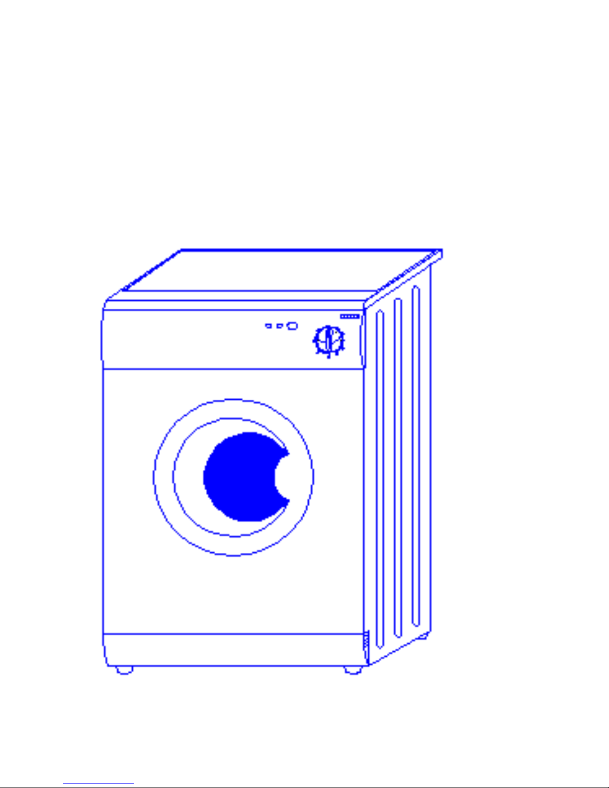
Your machine is a dryer that has been designed to last without complicated maintenance.
All the same, we would ask you to take care of a few small matters. If you follow these two
simple rules, we are sure that the dryer machine will stay your faithful friend and helper for a
long, a long time.
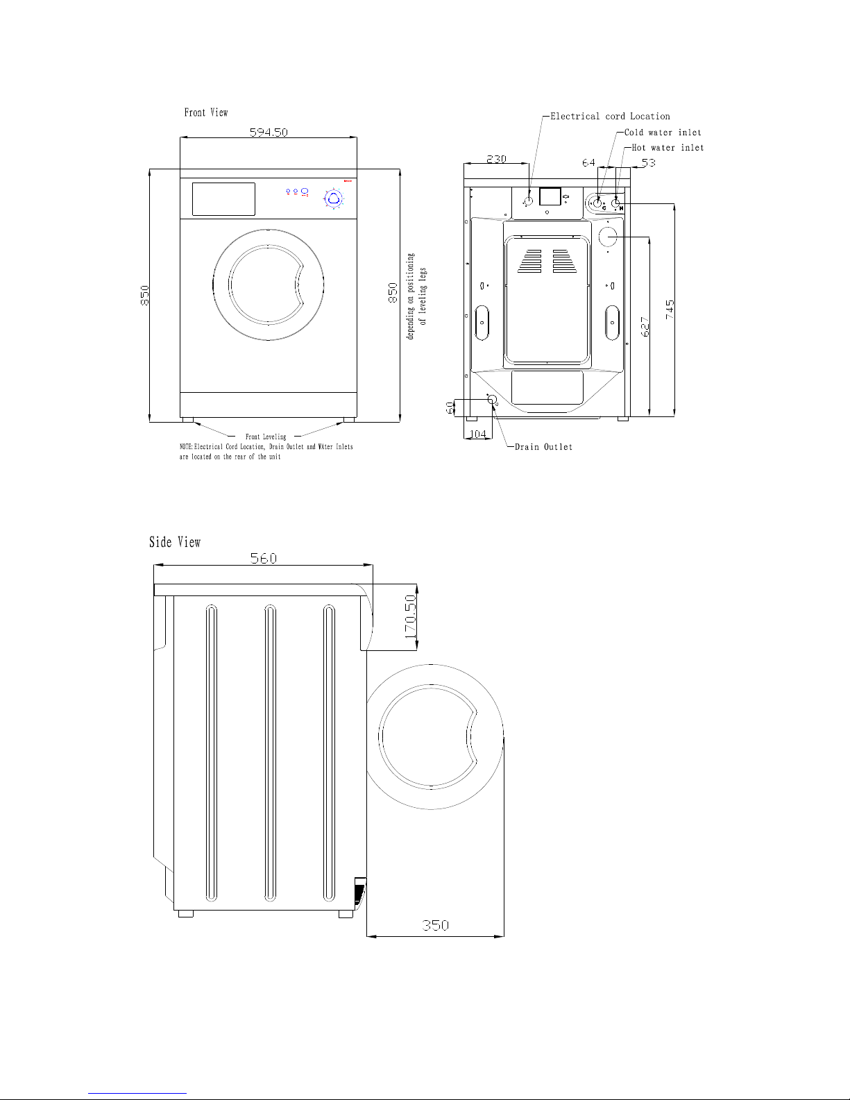
1. Ensure that your machine was installed according to the installation manual that comes
with this booklet.
2. Avoid at all costs using solvents either to clean the machine,
When you do not need a technician----
Even though your dryer has been carefully designed and constructed, something could still
go a miss with your machine. Before rushing to please check that the operations listed below
have been carried out. In many cases you will save time, money and bother. Our statistics
show that many of the calls received by our service centers could have been avoided with just
a little more attention.
Check that:
The plug is pushed right into the main sockets;
The door is closed tight;
The “ON/OFF” button has been pressed.
Check that:
The transit bolts have been removed (see installation manual);
The machine is level;
The drying load is according to instructions given in this booklet.
Check that:
The plug is fitted firmly into the main socket;
The door is properly closed;
The drying time knob is not in position”0”.
Check that:
The recommendations for the maximum loads and drying times
have been followed;
The drying time is set at least to 20 minutes;
The dryer won’t
start
The dryer
vibrates too
much
The dryer is
not drying
The dryer is
not drying
efficiently

5

6
DRYER MACHINE
REF.MODELS MJ9200D DESCRIPTION
1
Back panel
2
Cabinet assembly
3
Top panel assembly
4
Board panel
5
Switch cover
6
Timer (drying) knob
7
Lamp cover
8
Micro delaying device
9
Porthole catch
10
Porthole catch pin
11
Porthole catch spring
12
Porthole handle
13
Porthole inner frame
14
Porthole glass
15
Porthole frame
16
Support for porthole hinge
17
Porthole hinge
18
Kick plate cover assembly
19
Under plate
20
Feet
21
Vent hose flange
22
Support for capacitor

7

8
DRYER MACHINE
REF.MODELS MJ9200D DESCRIPTION
01
Tub
02
Drum
03
Tub cover gasket
04
Tub front flange
05
“U” bolt
06
Porthole gasket
07
Plug
08
Front-left countweight
09
Shock absorber
10
Shock absorber support
11
Tub suspension spring
12
Spring rest
13
Retaining ring
14
bearing 6205
15
Tub spider assembly
16
Bearing 6204
17
Driven pulley
18
Ply V belt
19
Blot. Drum pulley fixing
20
Porthole gasket fixing ring
21
Porthole gasket and tub fixing ring
22
Bolt M8X45, washer and nut M8
23
Screw M6X80 nut M6
24
nut-wash combine M6
25
plastic pin
26
Bolt M10 X40 and nut M10
27
Hose cabinet to tub

9

10
DRYER MACHINE
REF.MODELS MJ9200D DESCRIPTION
1
Dry Timer
2
Switch
3
Lamp
4
Wiring assembly
5
Cable assembly
6
Capacitor
7
Nut
8_11
Bush for motor
9
Motor spacer
10
Motor
12
Screw
13
3 Poles terminal board

11

12
DRYER MACHINE
REF.MODELS MJ9200D DESCRIPTION
1
Fan motor
2
The wire with fuse
3
Thermostat 2TT NC 125/85
4
Upper body of blower
5
Reflecting screen WDM
6
Heating element
7
Gasket of blower body WDM
8
Lower body of blower
9
Zipper for porthole gasket and blower
10
Fan nut
11
Fan group
12
Clips
Wiring circuit

13
Check and change 9200D motor
6P connector
Terminal
Description
Resistance
1-3
Auxiliary winding
15.1_
1-7
Primary winding
7.6_
3-7
A and P
22.0_
How to change the motor
1_Disconnect power and water supply from machine.
2_Move the machine to an open space for repair.
3_Remove back panel by removing three size SD3.5x13mm
screws.
4_Tilt the machine, wrest the two front feet two rounds
anticlockwise.
5_Tilt the machine forward, unscrew tow back feet, and then
take out under panel.
6_Fetch the V-belt from the pulley, and Tilt the washing
machine forwards.
7.Take off 8P plug housing and ground terminal of the wirings
from the motor socket.
8. Use short handle sleeve spanner unscrews right motor
Bolt size M6x217 and nuts M6.then pull out bolt.
9. Unscrew left motor bolt size M6x217 and nut M6, at the
Revised 10.04.2005

14
same time with your left hand support the motor in position.
Pull out bolt. Then take out motor from the button of the
machine carefully.
10. Change a new motor one by one at counter step.
11. Recover the machine and make a test to insure the
machine can work normally.
12.Complete.
How to change the drying timer.
1. Disconnect power from machine.
2. Remove top panel assembly by removing two size
SD3.5x13mm screws.
3. Pull out timer knob from control panel.
4. Unscrew two screw size M4x6 from control panel.

15
5. Take out drying timer from control panel.
6 Pull out all terminals of wiring.
7. Change a new timer and connect terminals as follows:
Plug terminal No: TAA of wiring to “a” terminal of timer,
Plug terminal No: TAA1 of wiring to “a1” terminal of timer,
Plug terminal No: TAB of wiring to “b” terminal of timer,
Plug terminal No: TAB1 of wiring to “b1” terminal of timer,
Plug terminal No: TAC of wiring to “c1” terminal of timer,
Plug ground terminal (green) of wiring to ground terminal of timer,
8. Use two screws size M4x6 amount timer to control panel .
9. Test machine.
10. Amount top panel assembly.
11. Complete.

16
Capacity
C=80F
Connection:
cx_c terminal of the wiring to terminals of capacity.

17
Fan motor
Connection: Plug terminal MV of wiring to upper terminal of fan motor.
Plug terminal TF of wiring to lower terminal of fan motor.
Micro delaying device
Connection:
plug IP_IPX terminal of wiring to micro delaying device as show above.

18
Fan
Heat element
Wire with fuse and Thermostat 2TT NC 125/85

19
Connection of dryer
1. Plug MV terminal of wiring to upper terminal of fan motor
2. Plug TF terminal of wiring to lower terminal of fan motor
3. Plug FEX and FE terminals of wiring to terminals with red
point of thermostats
4. Plug FDX and FD terminals of wiring to terminals with black
point of thermostats
5. Plug RA terminal to a terminal of heater.
Table of contents
Popular Washer manuals by other brands

Grundig
Grundig GWX 38232 R user manual

Whirlpool
Whirlpool AWE 6112 Instructions for use

Infiniton
Infiniton WM-98W1 Quick user manual

Continental Refrigerator
Continental Refrigerator LCA85BYI0 user manual

S.E.A. Group
S.E.A. Group RESCUE Intellitech DeconFilter Pro S manual

Frigidaire
Frigidaire atf7000es Use and care guide

Fisher & Paykel
Fisher & Paykel FabricSmart WA1068P Installation instructions and user guide

IKEA
IKEA UDDARP manual

Barton
Barton 99809 Owner's manual and safety instructions

Treedental
Treedental TR-DWD01 manual

Siemens
Siemens WM16XGH1GB User manual and installation instructions

Kenmore
Kenmore 11028042701 Installation instruction